
User`s manual


8: REGISTERS
1-78 EPSON S1D13504 SERIES HARDWARE FUNCTIONAL
SPECIFICATION (X19A-A-002-17)
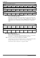
bit 3 GPIO11 Pin IO Configuration
When this bit = 1, GPIO11 is configured as an output. When this bit = 0 (default),
GPIO11 is configured as an input. Note the MD8 pin must be high at the rising edge of
RESET# to enable GPIO11, otherwise the VRTC pin is controlled automatically and this
bit will have no effect on hardware.
bit 2 GPIO10 Pin IO Configuration
When this bit = 1, GPIO10 is configured as an output. When this bit = 0 (default),
GPIO10 is configured as an input. Note the MD8 pin must be high at the rising edge of
RESET# to enable GPIO10, otherwise the HRTC pin is controlled automatically and this
bit will have no effect on hardware.
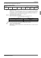
bit 1 GPIO9 Pin IO Configuration
When this bit = 1, GPIO9 is configured as an output. When this bit = 0 (default), GPIO9 is
configured as an input. Note the MD8 pin must be high at the rising edge of RESET# to
enable GPIO9, otherwise the DACRS1 pin is controlled automatically and this bit will
have no effect on hardware.
bit 0 GPIO8 Pin IO Configuration
When this bit = 1, GPIO8 is configured as an output. When this bit = 0 (default), GPIO8 is
configured as an input. Note the MD8 pin must be high at the rising edge of RESET# to
enable GPIO8, otherwise the DACRS0 pin is controlled automatically and this bit will
have no effect on hardware.
Note: GPIO8 and GPIO9 must always be set to the same function (both to input or both to out-
put).
The MD8 pin must be high at the rising edge of RESET# to enable GPIO8, otherwise the
DACRS0 pin is controlled automatically and this bit will have no effect on hardware.
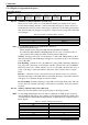
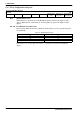
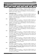
GPIO Configuration Register 1
REG[1Fh] RW
n/a n/a n/a n/a
GPIO11 Pin
IO Config.
GPIO10 Pin
IO Config.
GPIO9 Pin
IO Config.
GPIO8 Pin
IO Config.