
Power Supply User Manual


S1F76300 Series
S1F70000 Series EPSON 4–15
Technical Manual
S1F76300
Series
Output voltage response compensation
The S1F76380 series are provided with a response com-
pensation input. A response compensation capacitor is
connected between V
CONT and VO, allowing the ripple
voltage generated by the boosted output voltage to be
suppressed to a minimum.
Standby mode and battery backup
The S1F76310 series are equipped with a standby
mode, initiated by connecting PS to GND.
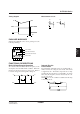
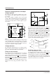
TYPICAL APPLICATIONS
Example Circuits
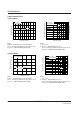
The output current, IO, and power conversion effi-
ciency, Peff of a particular device in a series depends on
In standby mode, the booster, including the crystal os-
cillator, is disabled (the switching transistor used to
drive the inductor is turned OFF) and the built-in
backup switch is turned ON, so that the input voltage at
V
I2 is output at VO. This enables the battery backup
function. PS is pulled-up internally, so when standby
mode is not required, the pin should be left open.
Powering up
Ensure that VO is at least the minimum operating volt-
age (0.9V) before switching on the booster circuit.
One way to do this is to attach a battery so that V
O never
drops below the minimum required for backup mode. If
no such external power supply is available, connect V
I2
to VI1 and hold PS Low when applying power for the
first time.
S1F76310 series
factors such as the switching frequency, type of coil,
and the size and type of other external components.
+
–
PWCR
V
O
circuit
V
I1
circuit
V
I1
RST
V
I2
C
Battery
PS
S1F76310M
C1
V
O
V
SW
LD
RST
V
I1
V
I2
GND
S1F76310M/C
PS
PWCR
R1
S1F76380 series
C1
V
O
V
SW
LD
RST
V
I1
GND
S1F76380M/C
PS
V
CONT
PWCR