
Power Supply User Manual


S1F76620 Series
S1F70000 Series EPSON 1–15
Technical Manual
S1F76620
Series
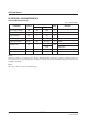
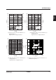
Recommended Operating Conditions
(Ta = –40 to +85°C)
Note 1
All voltages are based on the GND being 0V.
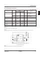
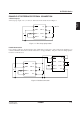
Note 2
The figure below shows the recommended circuit for operation with low voltages (V
DD = 1.5 to 2.2V):
P
OFF
R
L
C
L
*D
1
C
1
+
–
+
–
C
2
GND
OSC1
OSC2
* (DI (VF (IF=1mA) is recommended to be not more than 0.6V.)
V
O
CAP1+
CAP1–
V
DD
1
2
3
4
8
7
6
5
Recommended Circuit
Note 3
R
Lmin varies with input voltage. See Characteristics Graph (15).
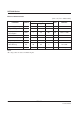
Max.
—
—
1.5
—
30
30
2000
—
Parameter
Step-up start operation
Step-up stop voltage
Output load resistance
Output load current
Oscillation frequency
External resistor for
oscillation
Step-up capacitor
Symbol
VSTA1
VSTA2
VSTP
RL
IO
fOSC
ROSC
C1, C2
Rating
Min.
1.5
2.2
—
RLmin
See note 3.
—
10
680
3.3
Unit
V
V
V
Ω
mA
kHz
kΩ
µF
Remarks
ROSC = 1MΩ
C
2 ≥ 10µF CL/C2 ≥ 1/20
See note 2.
ROSC = 1MΩ
ROSC = 1MΩ
—
—
—
—
—