
Power Supply User Manual


S1F76540 Series
2–28 EPSON S1F70000 Series
Technical Manual
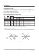
POFF1 POFF2 Functions
(High = V
DD
) (High = V
DD
)
Oscillator Booster Regulator Applications
Mode
(Low = VI) (Low = VI)
circuit circuit
PS1 High Low ON ON ON All circuits are turned on.
PS2 Low Low OFF OFF (*1) OFF (*2) All circuits are turned off.
PS3 High High OFF ON ON
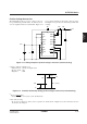
Slave unit side of parallel connection
(Booster and regulator)
PS4 Low High ON ON OFF
Master unit side of parallel
connection (Booster only)
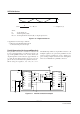
Power-off Control Function
The S1F76540 has the power-off function and turns on
or off each circuit function when control signals are en-
tered in the P
OFF1 and POFF2 pins from an external sys-
tem (such as microprocessor) as defined on Table 2.7.
This power-off function can also cut the reactive current
in parallel connection and other application circuits.
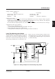
To use the dual-state, power-off control (all ON and all
OFF states) only, connect pin P
OFF2 to pin VI and use
only pin P
OFF1 for power-off control.
*1 When the booster circuit is off, approximately VI + 0.6 V voltage appears at VO pin.
*2 When the regulator is off, the V
REG pin becomes high-impedance state.
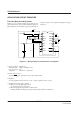
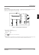
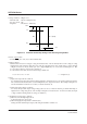
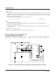
Application notes on power-off function:
• When using external system signals for power-on control, start to control the power only when V
I voltage
becomes stable after power-on. Unstable V
I voltage may destroy the IC permanently during on/off control.
Figure 2.6 Start timing of power-off control
Table 2.7 Available combination of power-off control
V
I
P
OFF1
P
OFF2
V
I
P
OFF1
P
OFF2