
Power Supply User Manual


S1F76540 Series
S1F70000 Series EPSON 2–37
Technical Manual
S1F76540
Series
◊
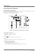
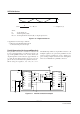
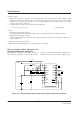
Setup conditions of Figure 2.16
• Internal clock : ON (Low Output mode)
• Booster circuit : ON
• Regulator : ON
• Thermistor resistor : RT
◊
Power-off procedure
• Set the P
OFF1 pin to low (VI) to turn off all circuits.
◊
Regulator temperature coefficient
• For the regulator setup and notes, see the “voltage regulator circuit” section of the function.
• The thermistor resistor (RT) has the non-linear temperature characteristics. To correct them to the linear char-
acteristics, insert the RP as shown Figure 2.16.
◊
Application in other setup conditions
• When used in the High Output mode, connect the FC pin to the V
I pin.