
Power Supply User Manual


S1F76640 Series
S1F70000 Series EPSON 2–49
Technical Manual
S1F76640
Series
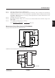
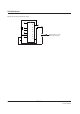
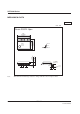
Measurement Circuit (Described on S1F76640M0A0)
Step-up circuit characteristic measurement circuit
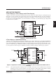
Stabilization circuit characteristic measurement circuit
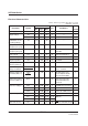
Note 1 : All voltage values are based on GND being 0V.
Note 2 : The value shown here is the step-up circuit conversion efficiency, and (V
O-VREG)IOUT is lost when the
stabilization circuit operates. So, it is recommended to operate this so that (V
O-VREG) becomes as small
as possible. When (V
O-VREG) × IO is large, the IC temperature rises and the characteristics of the
stabilization circuit change.
Note 3 : See Figures 6-5-14, 6-5-15 and 6-5-16.
Note 4 : R
SAT means inclination in Fig. 6-5-17, and VO-∆ (VO-VREG) indicates the lower limit voltage of the
V
REG output.
Note 5 : The calculation formula of C
T is as follows:
C
T=
V
REG (50˚C) – VREG (0˚C)
×
1
× 100 (%/˚C)
50˚C – 0˚C V
REG (25˚C)
1
2
3
4
5
6
7
8
16
15
14
13
12
11
10
9
A
A
V
I
OPR1
ROSC
C2
C1
C3
RL
IO
VO
C4
+
+
++
–
–
––
1
2
3
4
5
6
7
8
16
15
14
13
12
11
10
9
A
V
A
R
L
V
O
R
1
R
2
V
I
(R
RV
=R
1
+R
2
)
I
O