
Installation guide


1. Safety
RC180 Safety and Installation Rev.19 7
C3 series
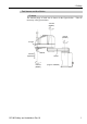
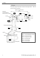
The motion range of each arm is shown in the figure below. Take all
necessary safety precautions.
Joint #1
Base
J1−
J1
+
J2+J2−
J3−
J4
−
J4
+
J5
−
J5
+
J6
−
J6+
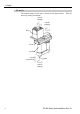
Arm #1
A
rm
#
2
(Lower Arm)
Arm #4
Joint #6
Joint #3
Joint #4
Joint #5
Arm #6
Joint #2
A
rm #5
J3+
LED Lamp
This lamp lights up
while the motors are ON.
Upper Arm (Arms #3 to #6)
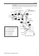
Joint Motion
Joint #1 : The whole Manipulator revolves.
Joint #2 : The lower arm swings.
Joint #3 : The upper arm swings.
Joint #4 : The wrist revolves.
Joint #5 : The wrist swings.
Joint #6 : The wrist rotates.
A
rm #3