
Installation guide


2. Installation
RC180 Safety and Installation Rev.19
42
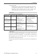
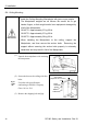
G / RS series
G
RS
G1
G3 G6 G10
G20
RS3 RS4
Max. Reaction torque on the
horizontal plate (Nm)
100 300 500 1000 1000 500 500
Max. Horizontal reaction force (N)
200 2000 2500 4500 7500 1200 1400
Max. Vertical reaction force (N)
300 1000 1500 2000 2000 1100 1100
Threaded holes for Mounting screw
M6 M8 M8 M12 M12 M6 M6
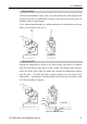
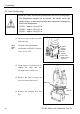
The plate for the Manipulator mounting face should be 20 mm thick or more and
made of steel to reduce vibration. The surface roughness of the steel plate should
be 25 μm or less.
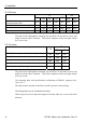
C3 / S5 series
S5
C3
701 901
Max. Reaction torque on the horizontal plate (Nm)
500 600 900
Max. Horizontal reaction force (N)
800 1000 1400
Max. Reaction torque on the vertical plate (Nm)
600 800 900
Max. Vertical reaction force (N)
2500 3000 3500
Threaded holes for Mounting screw M8 M10 M10
The plate for the Manipulator mounting face should be 30 mm thick or more and
made of steel to reduce vibration. The surface roughness of the steel plate should
be 25 μm or less.
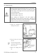
Use mounting bolts with specifications conforming to ISO898-1 property class:
10.9 or 12.9.
The table must be secured on the floor or wall to prevent it from moving.
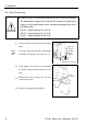
The Manipulator must be installed horizontally.
When using a leveler to adjust the height of the base table, use a screw with M16
diameter