
Installation guide

2. Installation
RC180 Safety and Installation Rev.19
61
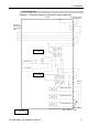
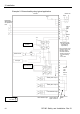
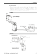
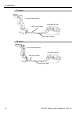
The signal from the Emergency Stop switch is designed to use two redundant
circuits.
If the signals at the two circuits differ by two seconds or more, the system
recognizes it as a critical error. Therefore, make sure that the Emergency Stop
switch has double contacts and that each circuit connects to the specified pins on
the EMERGENCY connector at the Controller. Refer to the Controller Manual
RC170 / RC180 Setup & Operation: 5.5 Circuit Diagrams.
)
NOTE
Checking Emergency Stop Switch Operation
Refer to 3.2 Development PC and Controller Connection and connect the
development PC and Controller before checking the function.
)
NOTE
Once the Emergency Stop switch is connected to the EMERGENCY connector,
continue the following procedure to make sure that the switch functions properly.
For the safety of the operator, the Manipulator must not be powered ON until the
following test is completed.
(1)
Turn ON the Controller to boot the controller software while pressing the
Emergency Stop switch.
(2)
Make sure that the seven-segment LED on the Controller displays
.
(3) Make sure that “E.Stop” is displayed on the EPSON RC+ 5.0 status bar.
(4) Release the Emergency Stop Switch.
(5)
Select EPSON RC+ 5.0-[Tools]-[Robot Manager]-[Control Panel] and click
the <Reset> button to execute the RESET command.
(6)
Make sure that LED is turned OFF and that “E-Stop” is
dimmed on the main window status bar.