
Specifications


SED1560 Series
7–6 EPSON
Microprocessor Interface
Number of pins
I/O Name Description
8 I/O D0 to D7 Data inputs/outputs
1 I A0 Control/display data flag input. This is connected to the LSB
of the microprocessor address bus.
When LOW, the data on D0 to D7 is control data.
When HIGH, the data on D0 to D7 is display data.
1 I RES Reset input. System is reset and initialized when LOW.
2 I CS1, CS2 Chip select inputs. Data input/output is enabled when
CS1 is LOW and CS2 is HIGH.
1 I RD (E) Read enable input. See note. 1
1 I WR (R/W) Write enable input. See note. 2
1 I C86 Microprocessor interface select input. LOW when interfacing to
8080-series. HIGH when interfacing to 6800-series.
1 I SI Serial data input
1 I SCL Serial clock input. Data is read on the rising edge of SCL and
converted to 8-bit parallel data.
1 I P/S Parallel/serial data input select
In serial mode, data cannot be read from the RAM, and D0 to D7,
HZ, RD and WR must be HIGH or LOW. In parallel mode, SI and
SCL must be HIGH or LOW.
Note 1
When interfacing to 8080-series microprocessors, RD is active-LOW. When interfacing to 6800-series microproces-
sors, they are active-HIGH.
Note 2
When interfacing to 8080-series microprocessors, WR is active-LOW. When interfacing to 6800-series microproces-
sors, It will be read mode when WR is high and It will be write mode when WR is LOW.
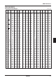
Data
Operating Data/co- Serial
P/S Chip select input/ Read/write
mode mmand clock
output
HIGH Parallel CS1, CS2 A0 D0 to D7 RD, WR —
LOW Serial CS1, CS2 A0 SI Write only SCL