EPSON ® Serial Interface for the GQ-3500 Printed in Japan m 88.
Serial Interface The serial interface is an option for your CQ-3500 printer. These pages tell you how to install and use the serial interface. The GQ-3500 serial interface is actually two interfaces in one. It can be used as either an RS-232C interface (the factory setting) or an RS-422 interface, depending on the settings of the jumpers on the circuit board.
For RS422 operation, set the jumpers at Jl and J2 as follows. At Jl, move REV, RD, and SRI to the right. At J2, set all jumpers in the installed position, except for TR+ and TR-. Jumpers that were not given a especific setting above do not need to be changed to select RS-232C or RS-422 operation (although they may affect how the interface works). 3. Select a baud rate by setting DIP switches 4-1, 4-2, and 4-3 as indicated in Table 2.
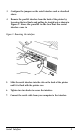
3. Configure the jumpers on the serial interface card as described above. 4. Remove the parallel interface from the back of the printer by loosening the two Knobs and pulling its straight out as shown in Figure 1. Store the parallel in the box that the serial interface came in Figure 1. Removing the interface 5. Slide the serial interface into the slot on the back of the printer until it is flush with the printer case. 6. Tighten two two knobs to secure the interface. 7.
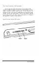
The Serial Interface DIP Switches On the right side of the serial interface are two banks of DIP switches, as shown in Figure 2. Group 4 is on the left and 5 is on the right.) switches control many of the of the interface ,as detailed in Table 1. You can use a ballpoint pen to change the switch settings. Because DIP switch groups 1 and 2 are the same for both the serial and parallel, the DIP switch information in Chapter2 and Appendix C applies to both interfaces Figure2.
Table 1.
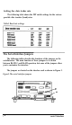
Setting the data trader rate The following table shows the DIP switch settings for the various possible data transfer (baud) rates Table2. Baud rate settings The Serial Interface Jumpers The following tables describe the functions of the jumpers on the serialinterface. The main function of these jumpers is to switch between RS-232 C and RS-422 operation, but some of the jumpers allow you to customize the interface. The jumpers are located on the interface card as shown in Figure 3. Figure3.
The jumpers at Jl The jumpers at J1 are two position jumpers. The small plugs can be moved from the left two wires to the right two wires to change the settings. Table 3 describes the functions of the jumpers at Jl. When delivered from the factory, all jumpers are in the left position. Table3.
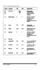
The jumpers at J2 Jumpers at J2 are single position jumpers; they can be either installed or disconnected. To change the settigs of these jumpers you must put a jumper plug across the two pins. To disconnect a jumper plug, simply move the plug so that it rests on the left pin only, leaving the right pin open. (All plugs are in this position when the interface is delivered from the factory.) Table. Function so the jumpers T2 Tl E L DM DM+ SD+ TR+ TR- Connects DM+ and DM- through a 120 ohm resistor.
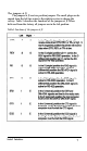
The GQ-3500 has a buffer that will hold up to 102 characters, including the ETX code at the end of the group. The computer can send the first group of characters and then stop until the first ACK is received. From then on,every time an ACK is received, another group of characters can be sent. DlP switch 5-2 controls ETX/ACK protocol. If DIP switch 5-2 iS Off, the GQ-35OO is ignored the ETX code.
1. When the input buffer becomes nearly full (within 128 bytes) 2 When the pinter goes off line (by pressing the ON LINE button) 3. When the printer runs out of paper 4. When the printer runs out of toner 5. When an error is detected. when the DTR signal goes low, the computer musts stop sending data within 128 characters The signal goes back high when the buffer has room for 255 Characters.
Table5.
Table 5.