
Stylus 200 and Stylus Color 200 Terminal Printer Service Manual

3.2.2 C199 MAIN Control Board and ASF Sensor Removal
1. Remove the upper case (see Section 3.2.1).
2.
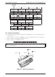
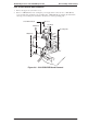
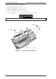
Remove 4CBB (M3×6) screws attaching the shield frame to the C160 MAIN Board.
3. Remove 7 connectors (CN1, CN8, CN7, CN4, CN3, CN5, CN6) on the main board. (Push CN6 down to
release cable on main board.) Then remove the C199 Main Control Board.
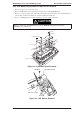
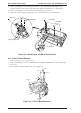
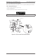
4. Remove a CBB (M3x6) screw fixing a ASF Sensor holder to printer mechanism.
When you replace the C199 MAIN Board, reset the EEPROM and perform the required
adjustments. (See Chapter 4.)
CBB(M3x6)
C160 PSB/PSE Board
ASF Sensor Holder
Figure 3-3. ASF Sensor Removal
CBB(M3x6)
CBB(M3x6)
CBB(M3x6)
CBB(M3x6)
Shield Plate
CN1
CN8
CN7
CN4
CN3
CN5
CN6
C199 Main Board
CN9
Figure 3-2. C199 Main Board Removal
CAUTION
EPSON Stylus Color 200 / EPSON Stylus 200 Disassembly and Assembly
Rev. A 3-3