EPSON COLOR INK JET PRINTER EPSON Stylus COLOR 3000 SERVICE MANUAL SEIKO EPSON CORPORATION 4007664 For other Service and User Manuals, go to www.ManualDepot.
NOTICE All rights reserved. Reproduction of any part of this manual in any form whatsoever without SEIKO EPSON’s express written permission is forbidden. The contents of this manual are subjects to change without notice. All efforts have been made to ensure the accuracy of the contents of this manual. However, should any errors be detected, SEIKO EPSON would greatly appreciate being informed of them.
PRECAUTIONS Precautionary notations throughout the text are categorized relative to 1) personal injury and 2) damage to equipment. WARNING Signals a precaution which, if ignored, could result in serious or fatal personal injury. Great caution should be exercised in performing procedures preceded by WARNING Headings. CAUTION Signals a precaution which, if ignored, could result in damage to equipment.
PREFACE This manual describes functions, theory of electrical and mechanical operations, maintenance, and repair of Stylus COLOR 3000. The instructions and procedures included herein are intended for the experience repair technician, and attention should be given to the precautions on the preceding page. The Chapters are organized as follows: CHAPTER 1. GENERAL DESCRIPTION Provides a general product overview, lists specifications, and illustrates the main components of the printer. CHAPTER 2.
TABLE OF CONTENTS CHAPTER 1. CHAPTER 2. CHAPTER 3. CHAPTER 4. CHAPTER 5. CHAPTER 6.
Chapter 1 Product Descriptions 1.1 Overview................................................................................................................1-1 1.2 Options and Consumables ..................................................................................1-2 1.3 Specification .........................................................................................................1-4 1.3.1 Printing Specifications...................................................................................
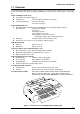
EPSON Stylus COLOR 3000 1.1 Overview The EPSON Stylus COLOR 3000 is a high-performance color ink jet printer designed for the office market as well as for plotter use with a wide paper availability up to full A2 size. The main features of this printer are: Paper availability in wide range A-2 (ANSI C-size) paper supported Printable area 410 mm (width) (A-2 /ANSI C-size paper) Left and right margin 5 mm (A2-size paper) 0.
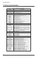
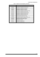
Product Descriptions 1.2 Options and Consumables Table 1-1.
EPSON Stylus COLOR 3000 Table 1-2. Options and Consumables (continued) Model S041071 S041072 S041107 S041073 S041075 S041074 S041126 S041124 S041125 S041123 S041063 S041064 S041106 S041103 S041102 S041132 S041131 S041130 Note) The asterisk is Rev.
Product Descriptions 1.3 Specification This section provides detailed information on the EPSON Stylus COLOR 3000. 1.3.
EPSON Stylus COLOR 3000 1.3.2 Control codes ESCP/2 and expanded raster graphics code EPSON Remote command IBM XL24E emulation 1.3.
Product Descriptions Combination of character tables and typefaces Table 1-5.
EPSON Stylus COLOR 3000 1.3.5 Paper Handling Cut Sheet Table 1-6. Cut Sheet Specification Paper Statement A5 B5 Executive A4 Letter Legal B4 ANSI B A3 A3 wide A2 ANSI C Paper Thickness Paper Weight 139.7 mm 148 mm 182 mm 184.2 mm 210 mm 215.9 mm 215.4 mm 257 mm 279.4 mm 297 mm 329 mm 420 mm 431.8 mm Width (5.5”) (5.8”) (7.2”) (7.3”) (8.3”) (8.5”) (8.5”) (10.1”) (11”) (11.7”) (13.0”) (16.5”) (17.0”) Length 215.9 mm (8.5”) 210 mm (8.3”) 257 mm (10.1”) 266.7 mm (10.5”) 297 mm (11.7”) 279.4 mm (11.
Product Descriptions Index Card Table 1-9. Index Card Specification Size A6 index card 105 mm (4.1”) (width) 148 mm (5.82”) (length) Paper Thickness 0.23 mm (0.0091”) or less Note) Make sure that the paper has no crease, curl, harshness or rip. Note) Label must be printed at normal room temperature. Labels (Cut Sheet) Table 1-10. Label Specification Size A4 Letter Width 210 mm (8.3”) 216 mm (8.5”) Length 297 mm (11.7”) 279 mm (11.0”) Paper Thickness 0.2 mm (0.
EPSON Stylus COLOR 3000 1.3.6 Printable Area Cut Sheet / Label (cut sheet) PW LM RM TM PL Printable Area BM Figure 1-3. Printable Area for Cut Sheet Table 1-14. Minimum Margins for Different Cut Sheet Sizes Paper width Up to 420 mm (16.5”) 420 mm (16.5”) A3 landscape A2 432 mm(17.02) ANSI B landscape ANSI C Rev. A Left margin Right margin Top margin Bottom margin 3 mm (0.12 inch) 5 mm (0.20 inch) 3 mm (0.12 inch) 5 mm (0.2 inch) 3 mm (0.12 inch) 3 mm (0.12 inch) 14 mm (0.
Product Descriptions Envelope RM LM TM Printable area BM Figure 1-4. Printable Area for Envelopes Table 1-15. Minimum Margin for Envelope Left Margin (minimum) 3 mm (0.12”) 1-10 Right Margin (minimum) 3 mm (0.12”) Top Margin (minimum) 3 mm (0.12”) Bottom Margin (minimum) 14 mm (0.55”) Rev.
EPSON Stylus COLOR 3000 Continuous Paper / Label (Continuous Paper) More than 13 mm (0.51") *1 More than 13 mm (0.51") *1 More than 3 mm (0.12 ") More than 12.5 mm (0.49") Printable are 1 Printable area 2 More than 9 mm (0.35") More than 9 mm (0.35") Printable are 1 Perforation Printable area 2 Printable area 2 More than 9 mm (0.35") More than 9 mm (0.35") Printable are 1 Perforation Printable area 2 Printable are 1 More than 134 mm (5.28") More than 14 mm (0.
Product Descriptions 1.3.7 Adjust Lever The adjust lever, located at the right and upper side in the printer cover, is used to adjust the gap between the paper and platen. The adjust lever must be set to the proper position according to the paper type to avoid ink smudging caused by ink’s contact with paper. Table 1-16. Adjust Lever Position Paper Type Cut sheet Transparency Continuous paper Envelopes Index card Lever Position Platen Gap Adjustment Value Far side (0) 0 mm Near side (1) + 0.
EPSON Stylus COLOR 3000 1.3.8 Ink Specification Black ink cartridge Table 1-17. Black Ink Cartridge Specifications Black Ink Cartridge Type Color Print capacity Ink life Storage Temperature Exclusive ink cartridge Black 3800 pages / A4 (ISO/IEC10561 Letter Pattern at 360 dpi) 2 years from indicated production date At storage -20 °C to 40 °C (-4 to 104°F)* 1 At packing storage -30 °C to 40 °C (-22 to 104°F)*1 At transit (Packed) -30 °C to 60 °C (-22 to 140°F)*1*2 Dimension 25.1 mm (W) X 139.
Product Descriptions 1.3.10 Electric Specifications 120 V version Rated voltage Input voltage range Rated frequency renege Input frequency range Rated current Power consumption Insulation resistance Dielectric strength AC 120 V AC 103.5 to 132 V 50 to 60 Hz 49.5 to 60.5 Hz 0.7 A (maximum) Approximately 21 W (ISO/IEC 10561 Letter pattern) Energy Star program compliant 10 M ohms min. (Between AC line and chassis, 500 VDC) AC 1,000 V rms. For 1 minute or AC 1,200 V rms.
EPSON Stylus COLOR 3000 1.3.12 Reliability Total print volume 75,000 pages (A3) Print head life 2,000 million dots /nozzle 1.3.13 Safety Approvals 120 V version Safety standards EMI UL1950 with D3 CSA22.2 No. 950 with D3 FCC part15 subpart B class B CSA C108.8 class B 220 - 240 V version Safety standards EMI EN 60950 (VDE, NEMKO) EN 55022 (CISPR Pub.22) class B AS/NZS 3548 class B 1.3.
Product Descriptions 1.4 Interfaces The EPSON Stylus COLOR 3000 is equipped with the parallel and Mac serial interfaces and a card slot for an optional Type-B interface. This section provides information on each interface. 1.4.
EPSON Stylus COLOR 3000 DATA DATA (n) DATA (n+1) STORBE 0.5 us (min.) 0.5 us (min.) 0.5 us (min.) 0 (min.) BUSY 0 (min.) ACKNLG 0 (min.) 5 us (type.) Figure 1-8. Data Transmission Timing Table 1-20. Data Transmission Timing Parameter Minimum Maximum tsetup 500 ns thold 500 ns tstb 500 ns tready 0 tbusy 500 ns tt-out 120 ns tt-in 200 ns treply tack*** 500 ns 10 us tnbusy 0 tnext 0 Note) tt-out shows the rise and fall time of every output signal.
Product Descriptions Table 1-22 shows the connector pin assignment and signals for forward channel of the parallel interface. Table 1-22. Connector Pin Assignments and Signals (Forward Channel) Pin No. Signal Name Return GND Pin I/O 1 /STROBE 19 I 2-9 DATA 0-9 20-27 I 10 /ACKNLG 28 O 11 BUSY 29 O 12 PE 28 O 13 SLCT 28 O 14 /AFXT 30 I 31 /INIT 30 I 32 /ERROR 29 O Description The strobe pulse. Read-in of data is performed at the falling edge of this pulse.
EPSON Stylus COLOR 3000 Reverse Channel Transmission mode IEEE-1284 nibble mode Adaptable connector Same as forward channel Synchronization Refer to the IEEE-1284 specification Handshaking Refer to the IEEE-1284 specification Data transmission timing Refer to the IEEE-1284 specification Signal level IEEE-1284 level 1 device See forward channel. Table 1-23 shows the connector pin assignment and signals for reverse channel of the parallel interface. Table 1-23.
Product Descriptions 1.4.2 Mac Serial Interface Standard RS-423 compliant Synchronization Synchronous Bit rate Approximately 900 Kbps, 1.8 Mbps Word format Start bit 1 bit Data bit 8 bit Parity bit No parity bit Stop bit1 bit Handshaking X-ON/XOFF, DTR protocol Adaptable connector 8-pin mini circular connector Recommended I/F cable Apple System Peripheral-8 cable Table 1-24. Connector Pin Assignment for Serial Interface Pin No. Signal Name I/O 1 2 3 4 5 6 7 8 SCLK CTS TxDS.
EPSON Stylus COLOR 3000 1.4.3 Optional Interface The EPSON Stylus COLOR 3000 supports an optional Type-B interface (Level 2) with the following characteristics.
Product Descriptions Table 1-27.
EPSON Stylus COLOR 3000 1.5 Operation This section describes the functions of each button on the control panel and LED printer status indicators. 1.5.1 Control Panel The control panel for this printer consists of 8 non-lock pushbuttons, 1 lock type pushbutton, and 13 LED printer indicators for easy operation of the various printer functions. Refer to Figure 1-10. Operate Ink Out Paper Out Cleaning Yellow Magenta Cyan Black 3 Sec. Pause Cleaning 3 Sec. LF/FF Media Type 5 Sec.
Product Descriptions Panel Functions (Normal Usage) Table 1-28.
EPSON Stylus COLOR 3000 Indicators This printer has 13 LED printer indicators, as shown in Table 1-30: Table 1-30. Printer Condition and Printer Status (1) LED Operate Paper Out Color Indication Green Green Green On Blinks On Blinks On Blinks On Blinks On Blinks On Blinks On Blinks On On Green On Photo Quality Ink jet Paper is selected. Green On Photo Quality Glossy Film is selected. Green On Ink jet transparencies is selected. Green On Paper type selection is neglected.
Product Descriptions 1.5.2 Default Setting Default setting mode enables users to change the default settings (initialization values). The set values are stored in the EEPROM and are not lost after the printer is turned off. To reset the values to the factory values, perform EEPROM reset operation or use the adjustment program described in Chapter 4. 1.5.2.1 Setting Method See Figure 1-11 for the default setting method. Start Press the "Media Type" button while turning on the printer.
EPSON Stylus COLOR 3000 1.5.2.2 Setting Menu The printer enters default setting mode when you press the Media Type button while turning on the printer. The menus available are shown Table 1-31. Table 1-31. Default Setting Menus Setting *1 Menu Print direction*2 Font Auto / Bi-d / Uni-D Roman / Sans Serif / Courier / Prestige / Script/ Roman T / Sans Serif H / Draft Pitch 10 cpi / 12 cpi / 15 cpi / 17.
Product Descriptions Table 1-32. Print Direction Mode Characteristics Black and White Printing Auto Bi-D Uni-D Throughput and quality is better. Throughput is the best. Print quality may be down. Throughput is worse. Print quality is the best. YMCK Printing (color) Throughput is better. Color quality with special paper worse. (Because Color correction depends the print direction.) Throughput is the best. Color quality with special paper worse.
EPSON Stylus COLOR 3000 1.5.3 Printer Adjustment Mode The EPSON Stylus COLOR 3000 allows users to adjust the following items. Table 1-35. Printer Adjustment Patterns Pattern No.
Product Descriptions 1.5.4 Printer Initialization This printer has three initialization types: Power-on initialization, Operator initialization, and Software initialization. Power-on Initialization Triggers Turning on the printer Cold reset command (Remote RS command) Actions performed Initialize the printer mechanism. Clears input data buffer. Clears download character set. Clears print buffer. Sets default values.
EPSON Stylus COLOR 3000 1.5.8 Error Condition When any of the conditions listed below is detected, the printer goes into an error status and the /ERROR signal goes LOW and the BUSY signal goes HIGH. On this condition, the printer accepts no data and goes into a pause status automatically. The CR moves abnormally. (Fatal error) Paper ends or paper is jamming. Release lever position is inappropriate for the paper path currently used. No ink cartridge is installed or ink ends. Maintenance is required.
Product Descriptions 1.6 Main Components The main components of the EPSON Stylus COLOR 3000 are as follows: Main control board Power supply board Control panel bard Printer mechanism Housing C203 MAIN C172 PSB/PSE C203 PNL M-4J60 1.6.1 C203 MAIN Control Board This board consists of the following: 16-bit CPU (IC5) (clock wave : 19.
EPSON Stylus COLOR 3000 1.6.2 C172 PSB/PSE Board C172 PSB/PSE board, same as for Stylus COLOR 1500, consists of the transformer, switching FET, regulator IC on the secondary circuit, diode bridge, fuse, and so on. Fuse Regulator IC Diode Bridge Transformer Switching FET Figure 1-14. C172 PSB/PSE Board Component Layout 1.6.3 Control Panel The control panel for this printer consists of 9 pushbuttons and 13 printer LED indicators. 1.6.
Chapter 2 Operating Principles 2.1 Overview................................................................................................................2-1 2.2 Printer Mechanism Operating Principle .............................................................2-1 2.2.1 Printer Mechanism ................................................................................................................. 2-1 2.2.2 Printing Mechanism ...............................................................................
EPSON Stylus COLOR 3000 2.1 Overview This chapter describes the operating principle of the printer mechanism and electrical circuit. 2.2 Printer Mechanism Operating Principle 2.2.1 Printer Mechanism The printer mechanism of this printer is composed of the printhead unit, paper feeding mechanism, ( arriage) mechanism and the pump mechanism. The block chart for the printer mechanism is shown in Figure 2-1. The printer mechanism has 3 motors: motor, PF (Paper Feed) motor and pump motor.
Operating Principles 2.2.2 Printing Mechanism The printing method used for this printer is On-demand ink jet, same as for other EPSON ink jet printers. However, use of the new type of printhead improves print quality and speed. The printing mechanism has 2 parts: printhead and ink cartridge which is filled with ink. 2.2.2.1 Printhead Structure The printhead for this printer has the black and color printheads. The structures of the printheads are basically the same except for the nozzle configuration.
EPSON Stylus COLOR 3000 2.2.2.2 Printing Process Steps bellow describe how the ink is ejected from each nozzle with the on-demand ink jet system. Normal state No print signal is applied to the PZT (Piezo electric element). In this state, the PZT does not displace and no pressure is added to the ink inside the cavity. Therefore the pressure in the cavity is kept at a constant level.
Operating Principles 2.2.3 Carriage ( ) Mechanism The mechanism is composed of the unit, timing belt, guide shaft, paper eject frame, (Home Position) sensor and motor. The motor sends torque to the timing belt to move the unit in the both right and left directions along the paper eject frame and guide shaft. A stepping motor used for the motor enables the unit to move and stop at any position.
EPSON Stylus COLOR 3000 2.2.4 Paper Feed Mechanism The paper feed mechanism of this printer consists of the integrated ASF (Auto Sheet Feeder) mechanism, tractor mechanism, PF (Paper Feed) motor, front/rear PE (Paper End) sensors, PF roller, paper guide mechanism, paper eject unit, and PF motor drive disengage mechanism. The torque from the PF motor drives the paper load mechanism, paper feed mechanism and paper eject mechanism.
Operating Principles 2.2.4.1 ASF (Auto Sheet Feeder) Mechanism When the printer is not printing, the motor drive disengage mechanism switches the torque sent from the PF motor to the LD rollers in the mechanism via the planetary gear based on the detected position of the unit. The roller shaft has 2 cams on the right and left ends. They push down the paper support to make the paper surface come in contact with the rollers.
EPSON Stylus COLOR 3000 2.2.4.2 Tractor Mechanism Torque sent from the motor to the roller is transmitted to the tractor gear via disengage mechanism operated with the release lever. When the release lever is set to the tractor side, the release sensor detects the condition and torque transmission to the ASF mechanism is cut off as a result. Tractor Gear Release Lever Tractor Disengage Gear Rear PE Sensor PF Roller PF Motor PF Motor Pinion Gear Figure 2-7. Tractor Mechanism 2.2.4.
Operating Principles 2.2.5 Platen Gap ( ) Adjust Mechanism The adjust mechanism, located at the top right of the printer cover, allows the user to set the proper platen gap (distance between paper and nozzle surface) for the paper thickness to prevent ink smudging. The adjustment mechanism consists of the adjust lever, guide shaft, and parallelism adjust bushings. Switching the lever from “0” to “1” turns the guide shaft which joins to the lever.
EPSON Stylus COLOR 3000 2.2.6 Ink System The ink system for this printer is composed of the following mechanisms. Ink cartridge Pump mechanism Capping mechanism Waste ink drain pads Wiping mechanism Figure 2-9 shows the block chart of the ink system. flowchart Ink Cartridges Cleaner Head for Black and Color Inks CR Unit Clutch Unit Pump Motor Combination Gear Air Valves Pump 1 Pump Unit Gear Pump 2 Waste Ink Drain Pads Figure 2-9. Ink System Mechanism Rev.
Operating Principles 2.2.6.1 Pump Mechanism The pump mechanism, composed of the pump motor and pump unit, absorbs viscous ink in the printhead nozzles and drains it to the waste ink drain pad through the cap. Since this printer has only one pump, it uses the pump for both black and color inks by alternating the rotational direction of the pump motor. 1 When the pump motor rotates forward * it absorbs black ink. On the other hand, it absorbs color ink with 2 backward rotation * .
EPSON Stylus COLOR 3000 2.2.7 Capping Mechanism Ink around head nozzles loses moisture If they are left exposed while the printer is in non-printing or power off status. Therefore the printheads must be capped to avoid increasing viscosity due to dried nozzles. The caps are individually equipped for the black and color printhead. When the moves right from the home position, the cap holder also shifts right and strikes the right frame. This motion opens the air valve and the air in the cap is release.
Operating Principles 2.2.7.1 Wiping/CR Lock Mechanism The wiping operation removes the ink and dust adhered around the nozzles. This is operated during a cleaning sequence. When the pump motor rotates backward, the torque sent via the head cleaner (wiper) drive gear and the clutch moves the head cleaner to the printhead route. The unit then begins to move right and left to wipe the nozzle surface against the head cleaner.
EPSON Stylus COLOR 3000 2.3 Electrical Circuit Operation Principles This printer consists of the following circuit board: C203 MAIN board C178 PSB/PSE board C203 Panel board Head driver circuits are directly attached to the black and color printheads. Figure 2-13 shows the block diagram of the electrical circuit. C203 PNL C172 PSB/PSE C203 MAIN Printer Mechanism Unit CR/PF/Pump Motors +5VDC +42VDC CR Unit Color Head Driver Circuit Black Head Driver Circuit Figure 2-13.
Operating Principles Figure 2-14 illustrates the electrical circuit diagram.
EPSON Stylus COLOR 3000 2.3.2 MAIN Control Board This printer uses MAIN for the main control circuit board. It consists of the following: 16-bit H8S/2655 (IC5) Runs at 19.66 MHz 2 gate arrays E05B33 (IC6) Manages interfaces, motors and printheads. E05B45 (IC16) P-ROM, DRAM and MROM Drivers Produces common voltage for printheads Drives motors. Table 2-8 and Figure 2-15 show the allocated functions for major components and the main control circuit block diagram, respectively.
Operating Principles C.G.
EPSON Stylus COLOR 3000 2.3.2.1 Reset Circuits The MAIN board contains two reset circuits: for logic line (+5 ) and power line (+42 ). Reset IC M51955BFP (IC3) monitors the +42 line. It outputs /NMI signal to the and the gate array to cut off the power line for the motors when the voltage level drops below 33.2 . Reset IC RST592D (IC9) monitors the +5 V line and sends low pulse when the voltage level drops below 4,2 .
Operating Principles Thermistor Thermistor is attached onto the color printhead to monitor the temperatures around the printhead. It functions to avoid change in ink viscosity, which affects printing result. The signal output from the sensor is directly transmitted to the analog port of the . ASF_PW : Output from the ASF PW (Paper Width) sensor. The ASF sensor uses a sliding potentionmeter. (The maximum resistance :10kΩ.) It is attached to the left edge guide in the ASF hopper assembly.
EPSON Stylus COLOR 3000 ASF_PQ :Output from the PQ (Paper Quantity) sensor. The paper quantity sensor uses a sliding potentionmeter. (The maximum resistance:10 ohms) The sensor ,attached to the right edged guide in the hopper assembly, detects the paper quantity between the maximum of 15 mm and the minimum of 3 mm. The detected quantity is converted into the corresponding resistance and the information is transferred to the analog port of the . When the 2 sensor detects the condition of 3.
Operating Principles 2.3.2.3 Motor Driver Circuits The gate array E05B45 produces the phase data (CRDA0-5) for the CR motor and sends it to 2-channel D/A converter in parallel data. When the phase-change trigger signal (CRTRG) is sent from the to the gate array, the A/B phase-change signal (CRDASEL) is output. Then the A-phase-data and B-phase-data are transferred to the channel A and channel B in the D/A converter, respectively.
EPSON Stylus COLOR 3000 2.3.2.4 PF Motor Driver Circuit The motor for this printer operates the following: Paper loading Paper feeding The gate array E05B33 (IC6) outputs the phase drive control signals (PFAPH and PFBPH), phase data signal (PFA0/1 and PPFB1/0) and voltage reference data (PFV) to the driver IC UDN2917EB (IC17). The driver IC then controls the phase current based on the voltage reference data. This sequence enables the micro step with a minimum of 1/720 inch at 2-2 phase.
Operating Principles 2.3.2.5 Printhead Driver Circuit This printer has 2 separate printhead driver circuits for the black and color printheads. Each circuit has the common voltage driver circuit attached to the circuit control board, and the nozzle selector circuit attached to the printhead. The each of the black and color common driver circuits is composed of the hybrid IC H8D2813E (IC22) and the terminal transistor.
EPSON Stylus COLOR 3000 Common driver circuit for the black printhead Gate array E05B33 (IC6) sends serial data to the head nozzle selector circuit on the printhead to select nozzles to be activated. Then the data is transferred to the common driver on the control board to drive all PZT that correspond to each nozzle.
Operating Principles Color printhead nozzle selector circuit The operating principle for the color printhead is the same as for the black printhead except that color print is performed with data for 3 different colors: yellow, cyan, and magenta. The operating principle for the color printhead is as described below: Nozzle selector circuit The nozzles for the color printhead are divided into 3: for yellow, cyan, and magenta with 64 nozzles for each of them.
EPSON Stylus COLOR 3000 Special printing This printer has the following special printing modes to print various types of graphic images. Each mode is selected through the printer driver based on the selected type of the paper and print quality. Double firing normal dot / Single dot printing mode This printer forms 1 dot with double ink ejection in the ANK or bitmap image mode. In the raster graphics mode which requires a high-resolution printing, however, forms 1 dot with a single ink ejection.
Operating Principles 2.4 Ink System Management This section explains how the ink system is controlled to protect the printheads and to ensure high print quality.
EPSON Stylus COLOR 3000 2.4.2 Counters The EEPROM on the control board stores the values for the following counters to manage the ink system: Protect Counter A This counter counts total amount of drained ink. If the counter value exceeds 75,000, the maintenance error occurs and the current printing job stops as a result. (Refer to Section 1.5.8.) The occurrence of this error requires ! clear operation and waste ink drain pad replacement. (Refer to Section 1.5.1 and Chapter 3.
Chapter 3 Disassembly and Assembly 3.1 Overview................................................................................................................3-1 3.1.1 Precautions for Disassembling the Printer.......................................................................... 3-1 3.1.2 Tools ........................................................................................................................................ 3-2 3.2 Disassembly and Assembly.........................................
EPSON Stylus COLOR 3000 3.1 Overview This section describes the procedures for disassembling the printer. Unless otherwise specified, no assembly procedures are included, since it is usually performed by reversing the disassembly. Points to note at disassembling and assembling is described under the heading . Adjustment required after assembling is described under the heading . Read precautions in Section 3.3.1 before disassembling and assembling.
Disassembly and Assembly 3.1.2 Tools Make sure you use the tools listed in Table 3-1. Table 3-1. Tools 3-2 Tools Distributor Part No.
EPSON Stylus COLOR 3000 3.2 Disassembly and Assembly This section describes procedures for disassembling and assembling the major units and parts. CAUTION Read CAUTION in Section 3.1.1 prior to disassembling the printer.
Disassembly and Assembly 3.2.1 Upper Housing Removal 1. Remove the knob, tip of the PG adjust lever, rear sheet guide, stacker and paper support. 2. Using tweezers, release the hooks which fixes the tractor unit to the printer mechanism. Then remove the tractor unit by lifting up the rear part of the tractor unit. Hook in the Tractor Unit Tweezers Tractor Unit Front Rear Figure 3-2. Tractor Unit Removal 3.
EPSON Stylus COLOR 3000 4. Remove 1 screw (CBS, 3X6) under the panel unit and 7 screws (CBP, 3X12) securing the upper housing to the lower housing. 5. Inserting tweezers from the bottom side of the lower housing, release 2 hooks fixing the upper housing to the lower housing. Then remove the upper housing by pulling it forward. WORK POINT When replacing the upper housing or printer cover, be sure to remove the label such as CAUTION and put it to the same position on the replaced part.
Disassembly and Assembly 3.2.2 ROM Replacement 1. Remove 2 screws securing the ROM cover to the bottom of the lower housing and remove the ROM cover. 2. Remove the ROM. CAUTION Be sure to disconnect the power cable from the AC socket before replacing the ROM. 3-6 Rev.
EPSON Stylus COLOR 3000 3.2.3 CR PW (Paper Width) Sensor Board Assembly Removal 1. Remove the upper housing. (See Section 3.2.1.) 2. Remove 2 screw (CBP, 3X8) and 2 plain washer (3X0.5X7) securing the damper cover to the CR unit. Note) If the any ink cartridge is installed, remove it to avoid ink leakage during disassembly and assembly. 3. Remove the damper cover. 4. Inset tweezers into the small cutout inside the CR unit to push the notch.
Disassembly and Assembly 3.2.4 Printhead Removal 1. Remove the upper housing. (See Section 3.2.1.) 2. Remove 2 screw (CBP, 3X8) and 2 plain washer (3X0.5X7) securing the damper cover to the CR unit. Note) If any ink cartridge is installed, remove it to avoid ink leakage during disassembly and assembly. 3. Remove the damper cover. 4. Remove the PW sensor cover securing the black and color head cables to the CR unit. Then release the black and color head cables. (See Section 3.2.3.) 5.
EPSON Stylus COLOR 3000 Tube Cover Tube Fixing Leaf Spring Head Fixing Screw Damper Assembly for Black Ink Damper Assemblies for Color Inks Color Printhead Black Printhead Plain Washer (6.3X0.2X8.3) Head Fixing Screw Compression Spring (9.9) Plain Washer (6.3X0.2X8.3) Color Printdead Cable Black Printhead Cable Tube Clamp CR PW Sensor Board Assembly CR Unit Figure 3-6. Black/Color Head Removal Rev.
Disassembly and Assembly 3.2.5 HP Sensor Removal 1. Remove the upper housing. (See Section 3.2.1.) 2. Disconnect the connector cable for the HP sensor from the sensor connector. 3. Using tweezers, release the hook securing the HP sensor to the HP sensor holder and remove the HP sensor. HP Sensor Holder Tweezers HP Sensor Holder HP Sensor HP Sensor Connector Cable HP Sensor Figure 3-7. HP Sensor Removal 3-10 Rev.
EPSON Stylus COLOR 3000 3.2.6 Printer Mechanism Unit Removal 1. Remove the upper housing. (See Section 3.2.1) 2. Disconnect the following connector cables from the connectors on the main board assembly: CN3 CN4 CN 5 CN6 CN7 CN10 CN11 CN12 CN13 CN14 CN18 CN20 CN21 CN22 CN23 3. Disconnect the ASF PW sensor connector cable from the PW sensor connector on the left edge guide of the ASF assembly. 4.
Disassembly and Assembly 3.2.7 PSB/PSE Board Assembly Removal 1. Remove the upper housing. (See Section 3.2.1.) 2. Remove the printer mechanism unit. (See Section 3.2.6.) 3. Remove 7 screws (6 CBS screws , 3X8 and 1 CBP screw, 3X12) securing the upper shield plate to the lower housing. 4. Disconnect the power cable and connector cable for the main board assembly from the CN1 and CN2, respectively. 5.
EPSON Stylus COLOR 3000 3.2.8 C203 MAIN Board Assembly Removal 1. 2. 3. 4. Remove the upper housing. (See Section 3.2.1.) Remove the printer mechanism unit. (See Section 3.2.6.) Remove the connector cable for the ASF PW sensor from the CN8 on the main board assembly. Remove the connector cable for the PL (Paper Length) sensor from the CN11 on the main board assembly. 5. Remove the connector cable for the PNL board from the CN17 on the main board assembly. 6.
Disassembly and Assembly Type-B I/F Board Guide ASF PW Sensor Connector Cable Earth Spring for Type-B I/F ASF PL Sensor Connector Cable CBS Screw (3X8) CBS Screws (3X8) CBS Screws (3X8) CN8 CBS Screw (3X8) CN15 CBS Screw (3X8) Main Board Assembly CN11 CN17 CP Screws (3X6) CBS Screws (3X8) Lower Housing Upper Connector Cover Figure 3-10. C203 MAIN board Removal 3-14 Rev.
EPSON Stylus COLOR 3000 3.2.9 Main Waste Ink Drain Pad Removal Note) In case the value for the protect counter A* has reached the limit and the maintenance error is indicated, or the value has exceeded 60,000, replace the waste ink drain pads on the agreement with your customer. *: The value for the protect counter A can be found on the sheet printed during the default setting mode. (Refer to Chapter 1, Section 1.5.2.1.) 1. Perform EEPROM reset. (See Section 1.5.1 in Chapter 1.) 2. Remove upper housing.
Disassembly and Assembly 3.2.10 PL (Paper Length) Sensor Removal 1. 2. 3. 4. Remove the upper housing. (See section 3.2.1.) Remove the printer mechanism unit. (See Section 3.2.6.) Disconnect the connector cable for the PL sensor from the CN11 on the main board assembly. Using tweezers, release 3 hooks securing the PL sensors to the lower housing. WORK POINT Make sure you connect each connector cable to the appropriate connector paying attention to the cable length which locates the proper connector.
EPSON Stylus COLOR 3000 3.2.11 Printer Mechanism Disassembly Section 3.2.11.1 thorough to Section 3.2.11.18 describe procedures for printer mechanism unit disassembly. 3.2.11.1 CR Motor Removal 1. 2. 3. 4. Remove the printer mechanism unit. (See Section 3.2.6.) Dismount the belt tension spring to loosen the timing belt. Remove the timing belt from the pulley on the CR motor.
Disassembly and Assembly 3.2.11.2 Pump Motor Assembly Removal 1. Remove the printer mechanism unit. (See Section 3.2.6.) 2. Remove the connector cable for the pump motor assembly securing the pump motor to the printer mechanism unit from the clump. 3. Remove 2 screws (CBS, 3x6) securing the pump motor assembly to the sub frame assembly. Then remove the pump motor assembly. CBS Screws (3X6) Pump Motor Assembly Sub Frame Assembly Figure 3-15. Pump Motor Assembly Removal 3-18 Rev.
EPSON Stylus COLOR 3000 3.2.11.3 PF Motor Assembly Removal 1. Remove the printer mechanism unit. (See Section 3.2.6.) 2. Remove the connector cable for the PF motor assembly from the clump attached to the printer mechanism unit. 3. Remove 2 screws (CBS, 3x6) securing the PF motor assembly to the left frame unit. Then remove the PF motor assembly. WORK POINT The PF motor pinion gear is made precise and easy to rust.
Disassembly and Assembly 3.2.11.4 Front/Rear PE Sensor Removal 1. Remove the printer mechanism unit. (See Section 3.2.6.) 2. Using tweezers, release 2 hooks securing the front and rear PE sensors to the rear paper guide assembly at the bottom of the printer mechanism unit. Then remove the sensors. 3. Disconnect the sensor connector cables from the sensor connectors.
EPSON Stylus COLOR 3000 3.2.11.5 Release Sensor Removal 1. Remove the printer mechanism unit. (See Section 3.2.6.) 2. Using tweezers, release 1 hook securing the release sensor to the left frame unit. Then remove the release sensor. Release Sensor Left Frame Unit Hook Release Sensor Connector Cable Figure 3-18. Release Sensor Removal Rev.
Disassembly and Assembly 3.2.11.6 Paper Eject Frame Unit Removal 1. Remove the printer mechanism unit. (See Section 3.2.6.) 2. Remove connector cables for the HP sensor and cover open sensor from the connectors on the sensors. 3. Remove 4 screws (CBS, 3X6) securing the paper eject frame unit to the printer mechanism unit. 4. Remove the paper eject frame unit from the printer mechanism unit by releasing the joint with the CR unit.
EPSON Stylus COLOR 3000 3.2.11.7 Pump Unit Removal 1. Remove the printer mechanism unit. (See Section 3.2.6.) 2. Remove the paper eject frame unit. (See Section 3.2.11.6.) 3. Remove 2 screws (1 CBS, 3X6 and 1 CBP, 3X8) securing the pump unit to the printer mechanism unit. Then remove the pump unit. Head Cleaner CBS Screws (3X6) Pump Unit Head Cleaner Lever (See Secction 3.2.11.14, Step 6.) Draining Pipe ASF Transmission Frame Unit Right Main Frame Sub Waste Ink Drain Pad CBP Screw (3X8) Figure 3-20.
Disassembly and Assembly 3.2.11.8 Edge Guide Unit Removal 1. Remove the printer mechanism unit. (See Section 3.2.6.) 2. Release the joints for the slide covers on the LD shaft and the edge guides. 3. Disconnect the connector cable for the PQ (Paper Quantity) sensor located at the right side of the right edge guide. 4. Remove 1 screw (CBS, 3X8) securing the ink cartridge holder to the middle frame so that the flange nut under the cartridge holder will be removed easily in the next step. 5.
EPSON Stylus COLOR 3000 WORK POINT When installing the edge guide unit to the printer mechanism unit, engage the edge guide unit with the main bottom frame, as shown in Figure 3-22. Be sure to fix the flange nuts with the specified adhesive. (See Chapter 6.) Spring Bottom Main Frame Edge Guide Unit Rear Front Figure 3-22. Joining the Edge Guide Frame and Bottom Main Frame Rev.
Disassembly and Assembly 3.2.11.9 PQ (Paper Quantity) Sensor Board Assembly Removal 1. 2. 3. 4. Remove the printer mechanism unit. (See Section 3.2.6.) Remove the edge guide unit. (See Section 3.2.11.8.) Remove 2 pan camera screws (2X5.5) securing the PQ sensor cover to the edge guide unit. Remove 1 tension spring securing the PQ sensor sub lever to the PQ sensor, and remove the PQ sensor sub lever. 5. Remove 1 pan camera 1B tight screw (2X3.5) securing the PQ sensor to the right edge guide.
EPSON Stylus COLOR 3000 3.2.11.10 ASF PW (Paper Width) Sensor Removal 1. Remove the printer mechanism unit. (See Section 3.2.6.) 2. Remove the edge guide unit. (See Section 3.2.11.8.) 3. Using a screwdriver or other pointing tool, release 1 hook securing the ASF PW sensor cover to the left edge guide unit. Then remove the PW sensor cover by opening it in 2 steps shown in Figure 3-24. 4. Remove the ASF PW sensor.
Disassembly and Assembly 3.2.11.11 Ink Cartridge Holder Unit Removal 1. 2. 3. 4. Remove the printer mechanism unit. (See Section 3.2.6.) Remove the paper eject frame unit. (See Section 3.2.11.6.) Remove the pump unit. (See Section 3.2.11.7.) Release 4 coupling screws (M6) connecting each ink tube unit to the corresponding ink cartridge holder unit, then disconnect the tubes. 5. Remove 4 screws (CBS, 3x6) securing the ink cartridge sub plate to the ink cartridge holder units. Then remove the sub plate. 6.
EPSON Stylus COLOR 3000 Ink Cartridge Supporting Plate CBS Screw (3x6) Cartridge Holder Unit Coupling Screw (M6) Ink Tube Unit CBP (3X8) CBP (3X8) CBP (3X8) Tube Fixing O-Ring CBP (3X8) CBS Screw (3x6) Yellow Magenta Cyan Black Ink Cartridge Fixing Plate Figure 3-25. Ink Cartridge Holder Removal Rev.
Disassembly and Assembly 3.2.11.12 Ink Sensor Assembly Removal 1. 2. 3. 4. 5. 6. Remove the printer mechanism unit. (See Section 3.2.6.) Remove the paper eject frame unit. (See Section 3.2.11.6.) Remove the pump unit. (See Section 3.2.11.7.) Remove the ink cartridge holders. (See Section 3.2.11.11.) Remove the ink sensor connector cables from the clump on the ink cartridge holder mounting plate. Remove 1 screw (CBS, 3X10) securing the ink sensor assembly to the ink cartridge holder mounting plate.
EPSON Stylus COLOR 3000 3.2.11.14 CR Unit Removal 1. 2. 3. 4. 5. 6. Remove the printer mechanism unit. (See Section 3.2.6.) Disconnect the HP sensor connector cable from the HP sensor. Remove the belt tension spring to loosen the timing belt. Disengage the timing belt from the pulley on the CR motor and the sub pulley. Remove 1 E-ring and 1 plain washer (6X0.7X12) from each end of the CR guide shaft. If the head cleaner lever* is locking the CR unit, push the lever down manually to unlock the CR unit.
Disassembly and Assembly WORK POINT Do not touch or damage the head surface in the removed CR unit. Be careful with static electricity in handling the printhead which has a head driver circuit directly attached. Pay attention to the oil pad when removing the CR guide shaft from the CR unit, since it tends to dislocate. When installing the CR guide shaft to the printer mechanism unit, fit the PG adjust lever to the cutout on the right frame assembly. (See Figure 3-27.
EPSON Stylus COLOR 3000 3.2.11.15 LD Shaft Removal 1. 2. 3. 4. Remove the printer mechanism unit. (See Section 3.2.6.) Remove the paper eject frame unit. (See Section 3.2.11.6.) Remove the CR unit. (See Section 3.2.11.14.) Remove 1 screw (CBP, 3x8) securing the ink supplying tube unit to the tube fixing holder on the printer mechanism with the tube fixing holder (B). Then release the tubes from printer mechanism. Tube Fixing Holder Base Frame Unit Tube Fixing Holder ;B CBP Screw (3x8) Figure 3-29.
Disassembly and Assembly 8. Remove 1 screw (CBP, 3X8) securing the paper eject drive unit to the left main frame assembly. 9. Attach the knob to the PF roller shaft. Then hold down the trigger lever on the right end of the PF roller, and turn the PF roller shaft until the edge guides don’t lift up any further. 10. Remove the paper eject drive unit by lifting up the front part of the unit.
EPSON Stylus COLOR 3000 LD Gear ASF Transmission Gear Set Bushing LD shaft LD Rollers E-ring Bushing Edge Guide PF Roller Figure 3-32. LD shaft Removal Gear ,29 (ASF Transmission Gear Set) ASF Transmission Ratchet LD Gear Figure 3-33. ASF Gear Set Engagement Rev.
Disassembly and Assembly 3.2.11.16 PF Roller Removal 1. 2. 3. 4. 5. 6. 7. Remove the printer mechanism unit. (See Section 3.2.6.) Remove the paper eject frame unit. (See Section 3.2.11.6.) Remove the CR unit. (See Section 3.2.11.14.) Remove the base frame assembly. (See Section 3.2.11.15, Step 4 to 10.) Remove the roller contact spring in the left part of the PF roller. Remove the trigger lever from the PF roller.
EPSON Stylus COLOR 3000 3.2.11.17 Rear Paper Guide Removal 1. 2. 3. 4. 5. Remove the printer mechanism unit. (See Section 3.2.6.) Remove the paper eject frame unit. (See Section 3.2.11.6.) Remove the CR unit. (See Section 3.2.11.14.) Remove PF roller shaft. (See Section 3.2.11.16.) Remove 2 screws (CBS, 3X6) securing the LD guide frame to the left frame unit and middle frame unit. Then remove the LD guide frame. 6.
Disassembly and Assembly 3.2.11.18 Middle Frame Unit Removal 1. Remove the printer mechanism unit. (See Section 3.2.6.) 2. Remove the Paper eject frame unit. (See Section 3.2.11.6 3. Remove the pump unit. (See Section 3.2.11.7) 4. Remove the edge guide.(See Section 3.2.11.8 5. Remove the CR unit. (See Section 3.2.11.14.) 6. Remove the LD shaft. (See Section 3.2.11.15.) 7. Remove the PF roller. (See Section 3.2.11.16.) 8. Remove 1 screw (CBS, 3x6) securing the LD frame guide to the middle frame unit. 9.
Chapter 4 Adjustment 4.1 Overview................................................................................................................4-1 4.1.1 Platen Gap Adjustment .......................................................................................................... 4-2 4.1.2 Input of Market Setting........................................................................................................... 4-4 4.1.3 Head Voltage Write Operation ................................................
EPSON Stylus COLOR 3000 4.1 Overview This section describes adjustment required after disassembling and assembling the printer. CAUTION Adjustment must be performed in the order shown in Table 4-1. Be sure to remove all ink cartridges from the printer when returning the printer to the customer. Use 720 dpi exclusive paper when printing the adjustment pattern. Table 4-1. Required Adjustment Occasion Printer mechanism is replaced. Main control board is replaced. Required adjustments 1.
Adjustment 4.1.1 Platen Gap Adjustment This adjustment is performed to obtain the appropriate gap between the head nozzle surface and the platen. It must be adjusted after reinstalling or replacing the CR guide shaft, CR unit or parallelism adjust bushing. The specified value range for the platen gap is 1.26 ± 0.02 mm. 1. Set the right and left parallelism adjust bushings to the middle of the adjusting range. 2. Place the thickness gauges at the illustrated positions in Figure 4-1.
EPSON Stylus COLOR 3000 Start Set the PG lever to "+". PG Adjustment Shift the CR to the left end. Does a 1.24-mm Gauge go through? Set the PG lever to "0". YES NO PG Adjustment Widen the PG. NO Is the left PG OK? Does a 1.28-mm Gauge go through? YES Set the PG lever to "+". NO YES Shift the CR to the right end. Narrow the PG. Set the PG lever to "0". PG Adjustment NO Return to the main flow. Is the right PG OK? YES Set the PG lever to "+". Shift the CR unit to the left end.
Adjustment 4.1.2 Input of Market Setting This operation is performed to write the market code into the EEPROM on the main control board. With this operation, all factory values are written in at a time. 1. Connect the printer and the host computer with a parallel interface cable. 2. Start the adjustment program in the host computer. 3. The market setting menu appears. Move the cursor using ↑ or ↓ key to select your marketing code from the list and press “Return” key.
EPSON Stylus COLOR 3000 4.1.3 Head Voltage Write Operation This operation is performed to write the printhead drive voltages in the EEPROM. You need to perform this operation whenever you replace the printhead. 1. Connect the printer and the host computer with a parallel interface cable. 2. Run the adjustment program in the host computer. 3. Perform “Market Setting”. (Refer to Section 4.1.2.) 4. Move the cursor using ↑ or ↓ key to select “2. Adjustment & Check from the Main menu.
Adjustment 4.1.3.1 Finding Out the Head Voltage Normally, the head voltage is not acknowledged without removing the printhead. This program is, however, designed to read the head voltage data stored in the EEPPROM on the main control board. This section describes how to find out the head voltages. 1. Connect the printer and the host computer with a parallel interface cable. 2. Run the adjustment program in the host computer. 3. Input the market code. (Refer to Section 4.1.2.) 4.
EPSON Stylus COLOR 3000 4.1.4 Black Head Angular Adjustment This adjustment must be made when replacing or disassembling the black printhead. Each printhead is held by the compression spring to the supporting point of the CR unit and the angle adjust lever located under the printhead. The adjust lever is used to swing the black printhead in parallel to the printing surface. With this operation, the nozzles on the printhead are aligned parallel to the paper feed direction.
Adjustment Start The printer prints the head angle adjustment pattern. Is the black head angle OK? Yes Is the color head angular OK? No Loosen the black head fixing screw by turning it 1/4. (See Figure 3-6 in Chapter 3.) What does the pattern show? Loosen the color head fixing screw by turning it 1/4. (See Figure 3-6 in Chapter 3.) Yes What does the pattern show? * * * No Move the black head adjust lever left. * * Move the color head adjust lever left.
EPSON Stylus COLOR 3000 4.1.5 Head Vertical Adjustment You must make this adjustment after removing or replacing one or both of the black and color printheads. With this adjustment, the vertical positions for the black and color printheads are aligned. This is performed by moving the head vertical adjust lever located on the right side of the CR unit to adjust the vertical position for the color printhead to the black printhead. 1. Connect the printer and the host computer with a parallel interface cable.
Adjustment 4.1.6 Head GAP Adjustment This operation is required when one or both of the black and color printheads are removed or replaced. This operation aligns vertical lines between black and color printheads toward the column direction. 1. Connect the printer and the host computer with a parallel interface cable. 2. Run the adjustment program in the host computer. 3. Input the market code. (Refer to Section 4.1.2.) 4. Move the cursor using ↑ or ↓ key to select “2.
EPSON Stylus COLOR 3000 Start Select "4. Gap" from the adjustment program. The printer prints the adjustment pattern in the LQ and SLQ modes. What does the pattern show? Gap Width Is the head gap OK? Yes Press "Return" key. No Change the value using key. Yes Change the value using key. Is the value correct? No End Press "0" key to correct the value. Press "Space" key to print. The printer prints another adjustment pattern in the LQ and SLQ modes. Is the head gap OK? No Yes Figure 4-7.
Adjustment 4.1.7 Uni-D Adjustment This is required when the CR unit or CR motor is replaced or removed. You perform this operation to adjust the deviation occurs between lines printed in the Uni-D mode. 1. Connect the printer and the host computer with a parallel interface cable. 2. Start the adjustment program in the host computer. 3. Input the market code. (Refer to Section 4.1.2.) 4. Move the cursor using ↑ or ↓ key to select “2. Adjustment & Check” from the Main menu.
EPSON Stylus COLOR 3000 Start Select "5. Uni-d" from the adjustment program. The printer prints the Uni-D adjustment pattern in the draft mode. What does the pattern show? Gap Width Is Uni-D OK? Yes Press "Return" key. End No Change the value using " " key. Yes Change the value using" " key. Is the value correct? No Press "Space" key to print. Press "0" key to correct the value. The printer prints another Uni-D adjustment pattern in the draft mode. Is Uni-D OK? No Yes Figure 4-8.
Adjustment 4.1.8 Bi-D Adjustment This is required when the CR unit or CR motor is replaced or removed. You perform this operation to adjust deviation occurs between lines printed in Bi-directional mode. 1. Connect the printer and the host computer with a parallel interface cable. 2. Start the adjustment program in the host computer. 3. Input the market code. (Refer to Section 4.1.2.) 4. Move the cursor using ↑ or ↓ key to select “2. Adjustment & Check” from the Main menu.
EPSON Stylus COLOR 3000 Start Select "6. Bi-d" from the adjustment program. The printer prints a Bi-D adjustment pattern in the LQ and draft modes. Is Bi-D OK? Yes Press "Return" key. End What does the pattern show? Gap Width No Change the value using " " key. Yes Change the value using" " key. Is the value correct? No Press "0" key to correct the value. Press "Space" key to print. The printer prints another Bi-D adjustment pattern. Is Bi-D OK? No Yes Figure 4-9.
Adjustment 4.1.9 Sensor Check This operation is performed to store several values in the EEPROM. The values and the sensors used are as follows: Value used as the basis for the detecting paper quantity remaining in ASF. PQ sensor attached to the right edge guide in ASF is used. Value used as the basis for the detecting paper width and the following sensors are used:. ASF PW (Paper Width) sensor attached to the left edge guide in ASF CR PW sensor attached to the right side of the CR unit.
EPSON Stylus COLOR 3000 4.1.9.1 PQ Sensor Adjustment CAUTION Follow the steps exactly in the way instructed. Otherwise the fatal error will occur. Inaccuracy in this adjustment does not guarantee the proper operation of the printer. 1. Enter the “Sensor Check” menu. (See Section 4.1.9.) 2. Move the cursor using ↑ or ↓ key to select “1.CR-PWS” and press “Return key. 3. Move the cursor using ↑ or ↓ key to select “2. ASF Quantity”. and press “Return” key. 4. Remove paper and press “Return” key. 5.
Chapter 5 Toubleshooting 5.1 General Description .............................................................................................5-1 5.2 Unit Level Troubleshooting .................................................................................5-4 5.3 Repair of the C172 PSB/PSE Board at Component Level ...............................5-10 5.4 Component Repair of the C203 MAIN Board ....................................................5-11 5.5 Repair of the M-4J60 Printer Mechanism ..............
EPSON Stylus COLOR 3000 5.1 General Description This section describes procedures for isolating the failure unit in 2 levels; unit level troubleshooting and the component level troubleshooting. Refer to the flowchart below to isolate the defective unit and perform repair at the component level. Table 5-1, Table 5-2 and Table 5-3 show the coil resistance for the motors, sensor status , and error codes and error condition, respectively.
Troubleshooting Table 5-2. Sensor Status Sensor HP sensor Connector No. Test pin No.
EPSON Stylus COLOR 3000 Table 5-3. LED Error Status and Solutions Printer Status Power Pause Paper Out Ink End Media Type Solution On Blinks Paper Out On After loading paper, press the Pause button and then press the Load/Eject button. Paper Jam Blinks After removing paper, press the Pause button and then press the Load/Eject button.
Troubleshooting 5.2 Unit Level Troubleshooting This section provides flowcharts which enable you to isolate the defective unit. Once the defective unit is identified by following the corresponding chart, proceed to Section 5.3 to identify more specific part to be replaced at the component level. Table 5-4. Symptom and Problem Symptom Problem The printer does not operate at all. No LED indicator lights up. An error is indicated. An error is indicated by LED indicators.
EPSON Stylus COLOR 3000 1. The printer does not operate at all. START Is the AC input voltage correct? NO Apply the correct AC input voltage. YES Has the fuse (F1) on the PSB/PSE board blown? YES Replace the fuse and disconnect the connector cable from the CN2 on the PSB/PSE board. NO NO Check the voltage level output from the CN2 on the PSB/PSE board. Is the voltage correct? Does the fuse blow again at power on? YES NO YES Replace the PSB/PSE board. Replace the MAIN board.
Troubleshooting 2. An error is indicated. START See Table 5-3 to identify the error type. Is it "Fatal error"? YES Turn off the printer and move the carriage manually. NO Does it move smoothly? Is it "No ink cartridge error" or "Ink low error"? YES NO YES Replace the ink cartridge with a new one. Check the CR motor and drivers. If they are normal, replace the MAIN board. NO YES Is it "Release lever error"? Reset the release lever and check if any paper is loaded in the printer.
EPSON Stylus COLOR 3000 3. Printing operation is abnormal. START Run the "Self-test". Does the "Self test" print? NO Are all connector cables connected to the main board properly? YES Is the printing result abnormal? YES NO NO Connect them properly. YES Perform adjustments. (Refer to Chapter 4.) Repeat cleaning sequence or perform initial ink charge operation. YES Is the problem corrected? NO Is the problem corrected? YES NO Check the motors, drivers, and printheads.
Troubleshooting 4. Paper is fed abnormally. START Is paper properly set in the ASF/tractor? NO Set the paper properly. YES Is "Paper Jam error" indicated? YES Remove the foreign objects located in the paper path. NO Is the problem corrected? Check the PF motor and driver. If they are normal, replace the main controlboard. Is the problem corrected? YES NO NO Clean the PF roller and the paper path. END YES YES Is the problem corrected? NO END Proceed to Section 5.
EPSON Stylus COLOR 3000 5. The control panel operates abnormally. START Is the control panel connector cable properly connected? NO YES Connect the control panel properly. Is the problem corrected? YES NO Replace the control panel. Is the problem corrected? YES END NO Replace the main control board. END Figure 5-6. Flowchart (5) Rev.
Troubleshooting 5.3 Repair of the C172 PSB/PSE Board at Component Level This section contains information which enables you to repair and replace the components on the electrical board (C172 PSB/PSE). Table 5-5 lists the potential causes for each symptom in order of possibility, with which you are able to find and repair the defective part. Table 5-5. Component Repair of the C172 PSB/PSE Board Symptom The printer does not operate at all. Condition Cause +42 VDC is Fuse (F1) is not output. open.
EPSON Stylus COLOR 3000 5.4 Component Repair of the C203 MAIN Board This section provides information which enables you to repair and replace defective components on the C203 MAIN board. Table 5-6 and 5-7 lists the causes for each symptom in order of possibility, with which you are able to find and repair the defective part. Table 5-6. Component Repair of the C211 MAIN Board Condition Cause Checkpoint Solution Symptom : The printer does not operate at all. Reset circuit is defective.
Troubleshooting Table 5-7. Component Repair of the C211 MAIN Board (continued)) Condition Cause Checkpoint Solution Symptom : CR does not operate normally. CR motor does not rotate Sub gate array IC16 Check the waveform for the Replace the MAIN normally. is defective. signals HPASEA/B (Pin 7) output board or IC16. from the IC19/20. HPASE on the IC20 (Pin 7) OUTA on the IC19 (Pin 10) Waveform (9) CPU is defective. IC19 or IC20 is defective. CR motor is defective. Replace the MAIN board.
EPSON Stylus COLOR 3000 Table 5-8. Component Repair of the C211 MAIN Board (continued)) Condition Cause Checkpoint Solution Symptom : The pump does not operate normally. Sub gate array IC6 is defective. Check the waveform for one of the Replace the MAIN board. following signals output from the IC18: PUA0/1 (Pin1/2) PUB0/1 (Pin23/24). Pin 18 on the IC18 The pump motor does not operate normally. Pin 24 on the IC18 Waveform (11) IC18 is defective. The pump motor is defective.
Troubleshooting 5.5 Repair of the M-4J60 Printer Mechanism This section provides information which allows you to repair and replace defective components of the M4J60 printer mechanism. Table 5-8, 5-9, and 5-10 contain various symptoms and the corresponding causes listed in order of possibility. Find the symptom in the table and troubleshoot the problem as instructed. Table 5-9 Repair of M-4I60 Printer Mechanism. Condition Cause Checkpoint Solution Symptom : The CR unit moves abnormally.
EPSON Stylus COLOR 3000 Table 5-10. Repair of M-4I60 Printer Mechanism(continued) Condition Cause Checkpoint Solution Symptom : CR motor operates abnormally (continued) CR moves slightly at CR does not power on, then stops. move smoothly. Move the CR manually and check if it moves smoothly. Clean and lubricate the CR guide shaft. (Refer to Chapter 6.) Check if the timing belt has appropriate Replace the tension tension. spring or timing belt. Check if the platen gap is proper. Adjust the platen gap.
Troubleshooting Table 5-11. Repair of M-4I60 Printer Mechanism(continued) Condition Cause Checkpoint Solution Symptom : Abnormal printing (continued) Vertical lines don’t align. Bi-$ is not properly adjusted. White banding problem occurs. The printhead is defective. Paper feed mechanism does not operate normally. Outline of the image Head angular is is not clear. not properly Color inks don’t print adjusted. properly. Head gap is not properly adjusted.
Chapter 6 Maintenance 6.1 Cleaning ................................................................................................................6-1 6.2 Service Maintenance ............................................................................................6-2 6.2.1 Head Cleaning......................................................................................................................... 6-2 6.2.2 Maintenance Request.......................................................................
EPSON Stylus COLOR 3000 6.1 Cleaning This chapter provides information on how to maintain this printer. This printer is basically designed to require no cleaning. It is, however, preferable to perform cleaning to preserve its function and printing performance in the optimum condition for a long period of time. Therefore be sure to perform occasional cleaning described in the following sections. WARNING Be sure to unplug the power cable from the AC power inlet before cleaning the printer.
Maintenance 6.2 Service Maintenance When an abnormal printing or the maintenance request error occurs, perform maintenance service described below. 6.2.1 Head Cleaning In case abnormal printing occurs, you can enter the printhead cleaning mode through the control panel operation. Also, to keep the printer in the best condition, the printer automatically selects the cleaning level (including flushing) and carries it out even while printing. Follow the steps below to enter the printhead cleaning mode. 1.
EPSON Stylus COLOR 3000 6.3 Lubrication and Adhesive Use of lubricant and adhesive has a considerable affect on the performance and durability of the printer. Especially, lubrication at low temperatures requires appropriate selection of the lubricant. Therefore, be sure to apply adequate lubricant and adhesive specified by EPSON based on the analysis of technical information and result from the experimental use of lubricants and adhesives in wide range.
Maintenance Table 6- 3. Adhesive Points NO. Adhesive Points 1 Point where the CR motor fan is attached to the CR motor shaft Right and left hexagon nuts in the edge guide unit 2 CAUTION Do not apply too much lubricant or adhesive to avoid printer malfunction. 6-4 Rev.
EPSON Stylus COLOR 3000 1 1 2 1 3 4 4 4 4 4 4 Figure 6-1. Lubrication Points (1) Rev.
Maintenance 6 9 9 7 9 9 9 9 9 9 Figure 6-2. Lubrication Points (2) 6-6 Rev.
EPSON Stylus COLOR 3000 CR Motor 1 CR Motor Fan Indent side facing outside 2 2 Figure 6-3. Adhesive Points Rev.
Appendix A.1 Connector Summary ..........................................................................A-1 A.1.1 Connector Pin Assignment .......................................................A-2 A.2 Circuit Diagrams.................................................................................A-9 A.3 Component Layout ........................................................................... A-16 A.4 Exploded Diagrams ..........................................................................A-21 A.
Appendix A.1 Connector Summary Figure A-1 illustrates the electrical interconnection of the main components.
EPSON Stylus COLOR 3000 A.1.1 Connector Pin Assignment Table A-1 shows the locations and descriptions for the connectors on the circuit boards in this printer. Tables from A-2 to A-13 show the pin assignment for each connector. Table A-1. Connector Summary Circuit Board Connector No. Pin No. C203 MAIN-B Board CN1 36 Parallel I/F (Refer to Section 1.3.1 and 1.3.2.) CN2 36 Type-B I/F (Refer to Section 1.3.4.
Appendix Table A-2. Connector Pin Assignment (CN3) Pin No. 1 2 I/O I Signal Name REL GND Description Release sensor signal Ground Table A-3. Connector Pin Assignment (CN4) Pin No. 1 2 I/O I Signal Name PE_F GND Description Front PE sensor signal Ground Table A-4. Connector Pin Assignment (CN5) Pin No. 1 2 I/O I Signal Name PE_R GND Description Rear PE sensor signal Ground Table A-5. Connector Pin Assignment (CN6) Pin No.
EPSON Stylus COLOR 3000 Table A-8. Connector Pin Assignment (CN9) Pin No. 1 2 I/O I Signal Name GAP GND Description Platen gap sensor signal Ground Table A-9. Connector Pin Assignment (CN10) Pin No. 1 2 3 I/O I Signal Name +5 GND ASF_PQ Description + 5 VDC Ground ASF PQ sensor signal Table A-10. Connector Pin Assignment (CN11) Pin No.
Appendix Table A-14. Connector Pin Assignment (CN15) Pin No. 1 2 3 4 5 6 7 8 9 I/O O Signal Name GND + 42 + 42 GND +5 GND PSC GND +5 Description Ground + 42 VDC + 42 VDC Ground + 5 VDC Ground Power off signal Ground + 5 VDC Table A-15. Connector Pin Assignment (CN17) Pin No. 1 2 3 4 5 6 7 8 9 10 11 12 13 14 15 16 17 18 19 20 21 22 23 24 25 Rev.
EPSON Stylus COLOR 3000 Table A-16. Connector Pin Assignment (CN18) Pin No.
Appendix Table A-18. Connector Pin Assignment (CN21) Pin No.
EPSON Stylus COLOR 3000 A-8 Rev.
Appendix A.2 Circuit Diagrams Figure A-2. C203 MAIN-B Board Circuit Diagram (1/2) Rev.
EPSON Stylus COLOR 3000 A-10 Rev.
Appendix Figure A-3. C203 MAIN-B Board Circuit Diagram (2/2) Rev.
EPSON Stylus COLOR 3000 A-12 Rev.
Figure A-4. C203 PNL Board Circuit Diagram LED4 LED5 LED6 LED7 LED8 LED9 LED10 LED11 LED12 SW0 SW1 SW2 SW3 SW4 SW5 SW6 SW7 PSW PSC LED11 LED10 LED9 LED8 LED7 LED6 LED5 LED4 LED3 LED2 22 18 17 16 15 14 13 3 2 1 9 8 7 SW0 1 SW1 1 SW2 1 SW3 1 SW4 1 SW5 1 SW6 1 SW7 1 5 SW8 21 20 19 12 11 4 10 2 2 2 2 2 2 2 2 1 2 3 6 5 4 A-13 Appendix GND LED1 LED0 LED1 LED2 LED3 6 24 23 25 LED0 +5V +5V LED12 Rev.
A-14 1 2 3 4 2.5A/125V or 250V F1 1M/0.5W R1 0.22U C1 2 L 1 N CN1 2 R2 3.9/5W C11 100-120VAC FG 2200P FG C4 220U/200V C8 1000P 4 3 HF2022-103Y0R7 L1 0.1u C2 2200P C3 1 DB1 D2SBA60 R12 R19 20K 11EQS04 D2 0.91/2W 1000P C31 39K R32 Q31 K1725 4700P C14 Q1 K2182 R18 3K HZS9A1L R31 IC1 TL431 10K 2 1 R13 4.7K R20 3 R14 510 Q3 2PA1015Y 390/0.5W R11 750K/0.5W R21 ZD31 R16 270 R15 510 0.01U C13 200K/0.5W Q2 C4408 C15 2200P/1.
Rev. A 1 C8 3 4 FG T1.25AH/250V F1 C4 1 2 N CN1 R12 D2 2/1W R19 20K 11EQS04 C11 56U/400V R2 10/5W 220-240VAC L 2200P FG 1M/0.5W R1 0.22U C1 2 1000P 4 3 HF2022-253Y0R4 L1 2 0.1u C2 2200P C3 1 DB1 S1VBA60 1000P C31 39K R32 Q31 K1725 2200P C14 K1603 Q1 R28 R16 270 R15 510 HZS9A1L 3K TL431 IC1 10K 2 1 R13 4.7K R20 3 R14 510 Q3 2PA1015Y 1.1K R11 R31 910K/0.5W R18 220K/0.5W R21 ZD31 C4408 4700P C13 300K/0.5W Q2 1000P/1.
EPSON Stylus COLOR 3000 A.3 Component Layout Figure A-7. C203 MAIN-B Board Component Layout (1) A-16 Rev.
Appendix Figure A-8. C203 MAIN-B Board Component Layout (2) Rev.
EPSON Stylus COLOR 3000 Figure A-9. C203 PNL Board Component Layout A-18 Rev.
Appendix Figure A-10. C172 PSB Board Component Layout Rev.
EPSON Stylus COLOR 3000 Figure A-11. C172 PSE Board Component Layout A-20 Rev.
Appendix A.4 Exploded Diagrams Figure A-12. Stylus 3000 Exploded Diagram (1) Rev.
EPSON Stylus COLOR 3000 Figure A-13. Stylus 3000 Exploded Diagram (2) A-22 Rev.
Appendix Figure A-14. Stylus Color 3000 Exploded Diagram (3) Rev.
EPSON Stylus COLOR 3000 Figure A-15. Stylus Color 3000 Exploded Diagram (4) A-24 Rev.
Appendix A.5 Dimension and Weight Dimension Weight :810 mm (W) X 565 mm (D) X 240 mm (H) 31.8 inch (W) X 22.2 inch (D) X9.4 inch (H) :22.5 Kg Figure A-12 illustrates the exterior dimension of the Stylus COLOR 3000. 385 mm (15.1") 565 mm (22.2") 434 mm (17.0") 240 mm (9.4") 793 mm (31.2") 810 mm (31.8") 380 mm (14.9") Figure A-16. Dimension of the Stylus COLOR 3000 Rev.
EPSON OVERSEAS MARKETING LOCATIONS EPSON AMERICA, Inc. EPSON DEUTCHLAND GmBH 20770 Madrona Avenue, P.O. Box 2842 Torrance, CA 90509-2842 Phone: (800)922-8911 Fax: (310)782-5220 EPSON UK LTD. Zülpicher Straße 6, 4549 Düsseldorf Germany Campus 100, Maylands Avenue, Hemel Hempstead, Herts, HP2 7TJ U.K. Phone: (+44)01442-61144 Fax: (+44)01442-227227 EPSON IBERICA, S.A. 68 bis, rue Marjolin 92300, Levallois-Perret France Phone: (1)4087-3737 Telex: 610657 EPSON ITALIA S.P.A. Avda.
EPSON SEIKO EPSON CORPORATION