“) EPSON TERM NAL PRINTER Myk. 800 SERVICE MANUAL EPSON ) 4001968 Rev.
NOTICE All rights reserved. Reproduction of any part of this manual in any form whatsoever without SEIKO EPSON’s express written permission is forbidden. The contents of this manual are subjects to change without notice. All efforts have been made to ensure the accuracy of the contents of this manual. However, should any errors be detected, SEIKO EPSON would greatly appreciate being informed of them.
PRECAUTIONS Precautionary notations throughout the text are categorized relative to 1) personal injury and 2) damage to equipment. DANGER Signals a precaution which, if ignored, could result in serious or fatal personal injury. Great caution should be exercised in performing procedures preceded by DANGER Headings. WARN/NG Signals a precaution which, if ignored, could result in damage to equipment.
PREFACE This manual describes functions, theory of electrical and mechanical operations, maintenance, and repair of stylus 800. The instructions and procedures included herein are intended for the experience repair technician, and attention should be given to the precautions on the preceding page. The chapters are organized as follows: CHAPTER 1. GENERAL DESCRIPTION Provides a general product overview, lists specifications, and illustrates the main components of the printer. CHAPTER 2.
Revision Issue Date Revision Page Rev. A December 18, 1992 First issue Added information: Chapter 2 (Page 2-23) Chapter 3 (Page 3-5/6) Chapter 6 (Page 6-1/2) Rev. B May 7, 1993 Rev. C June 11, 1993 Corrected the figure: Chapter 2 (Page 2-8) Rev.
TABLE OF CONTENTS CHAPTER 1. CHAPTER 2. CHAPTER 3. CHAPTER 4. CHAPTER 5. CHAPTER 6.
Chapter 1 General Description Table of Contents 1-1 1.1 FEATURES 1-2 1.2 SPECIFICATIONS 1.2.1 Printing Specification . . . . . . . . . . . . . . . . . . . . . . . . . . . . . . . . . . . . . . . . .1-2 1.2.2 Paper Handling Specification . . . . . . . . . . . . . . . . . . . . . . . . . . . . . . .. ...1-4 1.2.3 Paper Specification . . . . . . . . . . . . . . . . . . . . . . . . . . . . . . . ............1-4 1.2.4 Ink Cartridge . . . . . . . . . . . . . . . . . . . . . . . . . . . . . . . . . . . . . . .
List of Tables Table 1-1. Print Speed and Printable Columns . . . . . . . . . . . . . . . . . . . . . . . . . . 1-2 Table 1-2. Character Tables . . . . . . . . . . . . . . . . . . . . . . . . . . . . . . . . . . . . . . . . 1-3 Table l-3. Adjust Lever Settings . . . . . . . . . . . . . . . . . . . . . . . . . . . . . . . ......1-6 Table l-4. Environmental Conditions . . . . . . . . . . . . . . . . . . . . . . . . . . . . . . ...1-7 Table l-5. Electrical Specifications . . . . . . . . . . . . . . . . . . . .
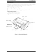
General Description STYLUS 800 Service Manual 1.1 FEATURES The Stylus 800 is a serial inkjet printer that uses a newly developed inkjet technology to accomplish a superb quality output with high-speed printing. The major features of this printer are: Ll High print quality from a new inkjet technology. Cl Fast printing of LQcharacters at 150 cps. Cl Compact design saves precious work space. Ci Built-in auto sheet feeder with a capacity fora maximum of 100 cut sheets (either A4 or Letter).
STYLUS 800 Service Manual General Description 1.2 SPECIFICATIONS This section provides detailed statistics for this printer. { 1.2.1 Printing Specification On-demand ink jet system 48 nozzles (12 nozzles x 4 staggered columns) Print system: Nozzle configuration: 0 Paper feed direction I. I i I i I. I i I i II I,,I I I i’ . ., * i # 4 Qi 5 . Figure 1-2. Nozzle Configuration Bidirectional printing with logical seeking control Printer direction: PMt speed: See Table 1-1. See Table 1-1.
Geneml Descri@ion STYLUS 800 Service Manual Character sets: Legal and 14 international character sets. Character tables: See Table 1-2. Table 1-2. Character Tables Character Table US Version European Version Pacific Version o o o o o o 0 0 0 0 0 o o o o o o o o 0 0 0 0 0 o ITALIC PC437 (U.S.
STYLUS 800 Sewice Manual General Description 1.2.2 Paper Handling Specification Feeding system: .f“” :. .. . Friction feed from built-in sheet feeder or manual insertion slot. Notes: The following operation are not al/owed. 1. Reverse feeding within 3 mm (O. 12 inches) from the top edge of the paper or 16 mm (0.63 inches) from the bottom edge of the paper. 2. Reverse feeding beyond 7.9 mm (0.3 inches). Feeding pitch: 1/6, 1/8 inch feed or programmable with a 1/360 inch minimum increment.
Geneml Description STYLUS 800 Service Manual Printable area: Cut Sheet (with built-in sheet feeder) B (Left marain)> — 4 c (Right marain]~ . r r ! A (Top margin) Printable area ID I (Bottom margin) 1 Figure 1-3. Printable Area - Cut S~eet (Built-in Sheet Feeder) Cut Sheet / Envelope (with the manual insertion slot) B (Left marain) ~.* c A (Top margin) Printable area L &ottom margin) Figure 1-4. Printable Area - Cut Sheet/ Envelope (Manual Insertion Slot) Note: Rev.
General Description SNLUS 800 Service Manual Adjust lever settings: The adjust lever, attached to the carnage unit, must be set to proper position for the paper thickness, as shown in Table 1-3. Table 1-3. Adjust Lever Settings Lever Position Paper Type LEFT Cut Sheets RIGHT Envelopes Paper Thickness ~;%26--00~iO!$ 0 . 1 6 - 0.52 mm (0.0063- 0.020”) Plain paper, (-.. I I \ /1 - . . . . . . . . . . . - . . . . . . . . .- -. I Figure 1-5. Adjust Lever 1.2.
Genera/ Descriptim STYLUS 800 Service Manual 1.2.5 Environmental Conditions Table 1-4. Environmental Conditions Operating Storage 10-35 ‘c (50 - 95 ‘I=)(*1) -20- 60 “C (-4 - 140 ‘F) (*2) Description Temperature 20- 80% RH (*1,*3) Humidity 5- 85~0 RH (*2,*3) Resistance to shock 1 G, within 1 msec. 2 G, within 2 msec. (*2) Resistance to vibration 0.15 G, 10-55 Hz 0.50 G, 10-55 Hz (*2) Note: ● 1 = Operating conditions must be in this range. *2= When the printer is in the shipping container.
STYLUS 800 Service Manual General Description 1.2.7 Reliability MTBF: MCBF: 4000 power on hours (POH) at a duty cycle of 10% Printhead life: 3 million lines (excluding the printhead) 1 billion dots per nozzle Total print volume: 75000 pages (with A4 or Letter size paper) 1.2.8 Safety Approval Safety standards: US version: UL1950 with D3 CSA22.
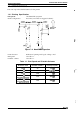
GenemlDescription SNLUS 800 Service Manual 1.3 INTERFACE SPECIFICATION The Stylus 800 is equipped with an 8 bit parallel interface, standard. 8 bit parallel STROBE pulse swchronization By BUSY and ACKNLG signals TTL-compatible level 36-pin 57-30360 (Amphenol) or equivalent See Figure 1-7. Data format: Synchronization: Handshaking: Signal level: Adaptable connector: Data transmission timing: i’b-\ DATA STROBE— — L- O. SuS(Min.) L!& O. SuS(Min.) O. SuS(Min.) Figure 1-7.
SNLUS 800 Service Manual General Description Table 1-6. Signal and Connector Pin Assignments (Continued) Signal Name Pin No. I/o Description 16 GND 17 CHASSIS-GND 18 NC Not USed. 19-30 GND Twisted-pair return signal ground. 31 INIT 32 ERROR o This signal goes LOW if the printer: - has a fatal error. - runs out of paper. 33 GND . Signal ground. 34 NC . Not USed. 35 +5V . Pulled up to +5 Vthrough 1.0 KW resistor in the printer. 36 - . Not used. (* Reserved.
STYLUS 800 Service Manual General DescriWion 1.4 PRINTER OPERATIONS This section describes the basic operations of the printer. 1.4.1 Control Panel The control panel of this printer contains five non-lock type push buttons and nine LED indicators for easy operation of the various printer functions. r \ [ O PAPER OUT O INK OUT II o jALT 5 I I ECONOMY /10 h.
STYLUS 800 Service Manual General Description 1.4.2 Panel Operation at Power On The following functions can be activated at power on by holding down the specified button on the control panel. Start the self-test printing mode by turning the printer on while holding down the FONT button. Start the built-in hexadecimal data dump print mode by returning the printer on while holding down the FONT and LOAD/EJECT buttons.
General Description SWLUS 800 Service Manual 1.4.4 Initial ink Charge When the printer is to be set up for primary use, whole ink supply path of the printer must be filled with a new ink, by performing the initial ink charge operation. [Step 1] Turn the printer on and press the PAUSE button to pause the printer. [Step 2] Open the printer cover and hold down the ALT button until the printhead moves to the ink cartridge replace position.
STYLUS 800 Service Manual General Description 1.5 MAIN COMPONENTS ,. . , (. The main components of this printer are: .! O Printer mechanism (M-481O) Q Main control board (C106 MAIN BOARD) ~ Power supply unit (C106PSB/PSEBOARD) Cl Control panel Cl Housing 1.5.1 Main Control Board (C106 MAIN BOARD) The C106 MAIN BOARD is the main conboller of the Stylus 800. It takes charge of interfacing with the host computer and processing of received print data, as well as control of the whole printer mechanism.
General Description STYLUS 800 Service Manual 1.5.2 Power Supply Unit (C106 PSBIPSE BOARD) The power supply unit converts input AC voltage and generates different DC voltages required by the printer mechanism and other electrical circuities. The C106 PSB BOARD is for 120VAC input, and the C106 PSE BOARD is for 220 to 240VAC input. — /- o Figure 1-10. C106 PSBIPSE BOARD Component Layout 1.5.
,. . . . . f.:,’ .
Chapter 2 Operating Principles Table of Contents 2.1 OVERVIEW 2-1 2-1 2.2 OPERATING PRINCIPLES OF THE PRINTER MECHANISM 2.2.1 Printer Mechanism . . . . . . . . . . . . . . . . . . . . . . . . . . . . . . . . . . . . . . . .. .2-2 2.2.2 Carriage Drive Mechanism . . . . . . . . . . . . . . . . . . . . . . ...............2-4 2.2.2.1 Platen Gap Adjust Lever . . . . . . . . . . . . . . . . . . . . . . . . . . . . . . . .2-4 2.2.3 Paper Feed Mechanism . . . . . . . . . . . . . . . . . . . . . . . . . . . . .
List of Figures ~...,, Figure 2-1. Functional Block Diagram of the Printer Mechanism . ...........2-1 Figure 2-2. Structure of Printhead . . . . . . . . . . . . . . . . . . . . . ...............2-2 Figure 2-3. Principles ofthe Printing Operation . . . . . . . . . . . . . . . . . . . . . ....2-3 Figure 2-4. Carriage Drive Mechanism . . . . . . . . . . . . . . . . . . . . . . . . . . . . . . . .2-4 Figure 2-5. Platen Gap Adjust Lever . . . . . . . . . . . .......................2-4 Figure 2-6.
Operating Principles STYLUS 800 Service Manual 2.1 OVERVIEW This section describes the operating principles of the printer mechanism and the electrical circuits of the Stylus 800. 2.2 OPERATING PRINCIPLES OF THE PRINTER MECHANISM The Stylus 800 printer mechanism is composed of the printhead unit, paper feed mechanism, carriage drive mechanism, pump mechanism, and various sensors. The figure below shows a functional block diagram of the printer mechanism. I I w.
STYLUS 800 Service Manual Operating Principles 2.2.1 Printer Mechanism The printer mechanism of this printer uses a drop-on-demand ink jet system similar to the system used on all other Epson ink jet printers. However, the printhead in this system is completely redesigned to make it compact and highly reliable. The figure below shows the structure of the printhead and ink supply system. ■ MLP MLP is the abbreviation for Multi-Layer Piezoelectric element.
Operating Principles STYLUS 800 Service Manual Principles of the Printing Operation The operation of the printhead to inject ink from each nozzle is: (1) Normal state No electrical charge is applied to the MLP (Multi-Layer Piezoelectric) element attached to the back of the cavity, and pressure inside the cavity is kept at constant level.
STYLUS 800 Service Manual Operating Principles 2.2.2 Carriage Drive Mechanism The timing belt attached to the base of the carriage unit is driven by the carriage motor, causing the carriage unit to move along the carriage guide shaft left to right, or vice versa. The carriage drive motor on this printer is a 4-phase, 200-pole, hybrid-type stepping motor mechanism, allowing the printer to stop the carriage or change the carriage movement at any position.
Operating Principles STYLUS 800 Service Manual 2.2.3 Paper Feed Mechanism This printer’s paper feed mechanism can feed paper either from the built-in ASF (auto sheet feeder) or the manual feed slot. The paper feed drive motor is a 4-phase, 4t3-pole, PM-type stepping motor that directly drives the paper feed mechanism (paper advancing operation, paper pick-up operation). This motor also drives the pump mechanism, but only when the printer is in the cleaning state. Table 2-3.
STYLUS 800 Sewice Manua) Operating Principles 2.2.4 Ink System !-. .:,, (.. This printer’s ink system is composed of the following mechanisms: ■ Ink cartridge ■ Pump mechanism E Cap mechanism H Printhead cleaning mechanism ■ Waste ink drain tank The figure below shows a diagram of the ink system. Ink Cartridge Head Driver Filter Boar {- ! Figure 2-7. Diagram of the Ink System 1 .. . 2-6 Rev.
Operating Principles STYLUS 800 Service Manual 2.2.5 Pump Mechanism The paper feed motor drives the pump mechanism when the transmission gear is moved to the position where the paper feed motor engages the pump mechanism gear trains, when the carriage unit is at the ink system home position. The figure below shows a block of the pump mechanism. Pump system operation depends on the rotational direction of the paper feed drive motor, as shown in table below.
STYLUS 800 Service Manual Operating Principles Table 2-4. Pump Mechanism Operation f“’., Operation PF Motor Rotational Direction CW (forward rotation) Pumping Pseudo-pumping (False absorbing) Gear backrush com~ensation CCW (backward rotation) Pump pulley reset Gear backrush compensation 1 (, The pump draws ink from the printhead nozzles and drains it into the waste ink drain tank. The printer performs this operation to eliminate dust or bubbles within the nozzles.
Operating Principles STYLUS 800 Service Manual 2.2.6 Cap Mechanism The cap mechanism prevents the printhead nozzles from drying or bubbles from forming inside the nozzle while the printer is not in use. The printhead capping operation is performed automatically so that a cap closely contacts the printhead surface when the carriage unit is moved to the ink system home position. 1 Carriage (Printhead) I . ‘d . I [ w :--, :: :: :: :: :: :: .I I I* .. .. .. .. F \ Slider Valve ,, :: c, :: :. ..
STYLUS 800 Service Manual Operating Principles 2.3 OPERATING PRINCIPLES OF THE ELECTRICAL CIRCUITRIES ,,, 1, The Stylus 800 contains the following circuit board units: f ... ■ C106 MAIN BOARD (Main control circuit board) ■ C106 PSB/PSE BOARD (Power supply circuit board) In addition to the circuit boards above, part of the printhead drive circuit is built on a separate circuit board installed in the carriage unit, and the printhead is attached directly to this board.
Operating Principles STYLUS 800 Service Manual The figure below shows a block diagram of the power supply circuit (C106 PSB/PSE). This power supply circuit employs the RCC (ringing choke converter) switching control system. The input AC voltage supplied from the external AC source is first input to the filter circuit for higher harmonics absorption. The AC voltage is then input to the rectification and smoothing circuit, converting it into DC voltage.
STYLUS 800 Service Manual Operating Principles 2.3.2 Operating Principles of the Main Control Circuit The main control circuit of this printer is the C106 MAIN BOARD. This circuit is controlled by the 8-bit CPU TMP96C141F (ICI), running at 19.6608 MHz. This CPU has a unique architecture capable of handling data on the data bus at either an 8-bit bus width or a 16-bit bus width. Due to this, a 16-bit data bus width-type ROM is used on this board, increasing the internal processing speed.
Operating Principles STYLUS 800 Service Manual 2.3.2.1 Reset Circuits The C106 MAIN BOARD contains two reset circuits: the +5 V monitor reset circuit and the +35 V monitor reset circuit. The +5 V monitor reset circuit monitors the voltage level of the +5 V line, using reset IC PST592 (IC12), and outputs a reset signal to both the CPU (ICI, TMP96C141) and the E05A85EB gate array (IC3), when the voltage level drops below +4.2 V.
STYLUS 800 Service Manual Operating Principles 2.3.2.3 Ink End Detection The IE (Ink End) sensor attached to the carriage detects, not only the ink end, but also when ink is low and whether an ink cartridge is installed. The detected status is classified to five modes according to the output voltage level of the IE sensor.
Operating Principles STYLUS 800 Service Manual 2.3.2.4 Carriage Motor Drive Circuit I Carriage motor drive IC SLA7024 (IC13) drives the carriage motor for the printer mechanism by a constant current, unipolar drive system. Gate array E05A85EB (IC3) selects the motor phase drive current level using the output signals from ports CRO to CR3 (pins 75 to 78). The phase switching operation is directly controlled by the phase control signals output from ports P600 to P603 (pins 1 to 4) of the CPU.
STYLUS 800 Service Manual Operating Principles 2.3.2.5 Paper Feed Motor Drive Circuit ; ~.,‘ c .. The paper feed motor for this printer drives the following mechanisms: 9 Paper feed mechanism ■ Paper pickup mechanism ■ Pump mechanism Driver IC SMA6501 (QM1) drives the paper feed motor by a constant voltage, unipolar drive system. The CPU outputs phase control signals from ports P610 to P613 (pins 5 to 8) for the phase switching operation.
Operating Principles STYLUS 800 Service Manual 2.3.2.6 Printhead Drive Circuit The printhead drive circuit for this printer is composed of the following two parts: ❑ Common drive circuit (trapezoidal drive pulse generation) ■ Head drive circuit (nozzle control built on the printhead) The 64-bit thermal head driver SED5620D in the head drive circuit on the printhead is used as a nozzle selector to drive the printhead nozzles selectively.
SNLUS 800 Service Manual Operating Principles 2.4 INK SYSTEM MANAGEMENT #“’ ,,, This section explains how the ink system is controlled to protect the printhead and the ink supply system and to ensure highquality output. The ink system control is composed of the following operations: t..
Opmeting Principles STYLUS 800 Service Manual 2.4.1 Ink Operations There are various ink operations that can be performed selectively by the printer. 2.4.1.1 Power on Operation Power on consists of the following operations, and only one of these operations is performed, depending on the position of the carnage when the printer is turned on. ■ At ink system home position 1) Moves the carriage to the flushing position and performs the flushing operation.
STYLUS 800 Service Manual Operating Principles 2.4.1.3 Standby Operation The standby operation prevents an increase in the viscosity of the ink held inside the printhead nozzles. This operation is performed automatically if no data is received for more than three seconds from the last print data. 1) Counts the number of flushing operations from the last standby operation, using the combined print counter N. And performs the flushing based on the counter value. 2) Moves the carriage to the home position.
STYLUS 800 Service Manual Operating Principles 2.4.1.6 Cleaner Blade Operation The cleaner blade operation eliminates any dust or ink attached to the nozzle plate surface. This operation consists of the following separate operational modes. This operation eliminates any dust attached to the nozzle plate surface before the ink absorbing operation is performed. 1) Sets the cleaner blade. 2) Moves the carriage to the cleaner start position.
STYLUS 800 Service Manual Operating Principles 2.4.1.8 Disengage ON Operation This operation sets the switch lever to the position where it transmits the PF motor drive to the pump mechanism. {“’”” 1) Moves the carriage to the position D where the lever is set to the specified position. 2) Moves the carriage to the position B. 3) Release a mechanical pressure of the paper feed drive mechanism. (Generates a backlash.) 4) Moves the carriage to the false absorbing position.
STYLUS 800 Semice Manual Operating Principles 2.4.2.4 Protect Counter There are four protect counters to manage the amount of ink draining to the waste ink drain tank. The value of these counters is stored in EEPROM on the main board upon power off. t ■ Prot@ counter A I I This counter is used to manage the total amount of drained ink. If the counter value is equal to or exceeds 25000 (A 2 25000), the printer indicates the error on the contiol panel and maintenance is required.
Chapter 3 Disassembly and Assembly Table of Contents 3-1 3.1 OVERVIEW 3.1.1 Precautions for Disassembling the Printer . . . . . . . . . . . . . . . . . . . . .. ...3-1 3-2 3.2 DISASSEMBLY AND ASSEMBLY 3.2.1 CASE, UPPER Removal . . . . . . . . . . . . . . . . . . . . . .................3-3 3.2.2 Power Supply Unit (C106 PSB/PSE BOARD) Removal . .............3-4 3.2.3 Main Controller (C106 MAIN BOARD) Removal . ...................3-5 3.2.4 PRINTER MECHANISM (M-481O) Removal . . . . . . . . . . . . . . . . .
STYLUS 800 Service Manual Disassembly and Assembly 3.1 OVERVIEW This section describes procedures for disassembling the main components of this printer. Unless otherwise specified, the disassembled unit or components can be reassembled simply by reversing the disassembly procedure. The assembly procedure is, therefore, omitted. Precautions for any disassemble are titles “~sassemblY/As*mblY points”. Adjustments . , or assemblv. Procedure required after assembling the unit are titled “Required Adjustrn&ts”.
STYLUS 800 Service Manual Disassembly and Assembly 3.2 DISASSEMBLY AND ASSEMBLY Follow the instruction in Section 3.1.1 to disassemble the prt”nter. I This section consists of the subheads shown in the diagram below. Refer to the exploded view of the printer in the Appendix, if necessary. F1 START CASE, UPPER Removal & 3.2.1 Page 3-3 Power Supply Unit (C106 PSB/PSE) Removal I 3.2.2 Page 3-4 I v Main Controller (C106 MAIN) Removal 3.2.
STYLUS 800 Service Manual Disassembly and Assembfy 3.2.1 CASE, UPPER Removal [Step 1] Remove the COVER, PRINTER by releasing the tabs holding it to the CASE, UPPER. [Step 2] Remove the SUPPORT, PAPER by releasing the tabs holding it to the CASE, LOWER. [Step 3] Remove the GUIDE, PAPER, REAR. [Step 4] Remove the CONTROL PANEL. (Release the tab by inserting a screwdriver into the hole in the CASE, UPPER, as shown in figure below.) [Step 5] Remove 2 screws (CBB screw (M3 x 12) x 2).
Disassembly and Assembly STYLUS 800 Service Manual 3.2.2 Power Supply Unit (C106 PSB/PSE BOARD) Removal [Step 1] Remove the CASE, UPPER. (Refer to Section 3.2.1.) [Step 2] Disconnect the cables from comectors CN1 and CN2 of the C106 PSB/PSE BOARD. ,:,, .( [Step 3] Remove 4 screws (CBB screw (M3 x 6) x 2, CBS screw (M3 x 6), CB(0) screw (M4 x 8)) fixing the power supply unit to the lowercase, as shown in figure below.
STYLUS 800 Service Manual Disassembly and Assembly 3.2.3 Main Controller (CI06 MAIN BOARD) Removal [Step 1] [Step 2] [Step 3]. Remove the CASE, UPPER. (Refer to Section 3.2.1.) Disconnect the cables from the connectors CN2/CN3/CN4/CN5 /CN6/CN7 of the C106 MAIN BOARD. Remove 4 screws (CBB screw (M3x1O)X2,CBS screw (M3x6)x2) and take out the main controller. . I I I I I I I I I . ■ ■ ■ When you replace the main board, initialize the EEPROM contents as follows: Reassemble the printer.
Disassembly and Assembly STYLUS 800 Service Manual 3.2.4 PRINTER MECHANISM (M-481O) Removal [Step 1] [Step 2] [Step 3] [Step 4] . [Step 5] ■ m Remove the CASE, UPPER. (Refer to Section 3.2.1.) Remove the power supply unit. (Refer to Section 3.2.2.) Remove the main controller. (Refer to Section 3.23.) Move the carriage to the center of the ptiner. Remove 4 screws (CB screw (M4x16)x4) and take out the printer mechanism. Wipe ofl any.
Disassembly and Assembly SNLUS 800 Servke Manual 3.2.5 PRINTER MECHANISM Disassembly The procedures described in this section explain removal of components within the printer mechanism. 3.2.5.1 PRINTHEAD UNIT Removal [Step 1] Remove the printer mechanism. (Refer to section 3.2.4.) [Step 2] Move the carriage to the middle of the printer. The carriage is located between first and second paper guide roller, as illustrated in figure below. Pull the ink cartridge clamp towards you and remove the ink cartridge.
STYLUS 800 Service Manual Disassembly and Assembly Ink Cartridge o 0“ Q I @ Printhead Unit a -. 22% =’5” ~ %.. \ / Figure 3-7. PRINTHEAD UNIT Removal (Continued) 3-8 Rev. A ..:-. f,.
SNLUS 800 Sewice Manual Disassembly and Assembly 3.2.5.2 PUMP UNIT Removal [Step 1] Remove the PRINTER MECHANISM. (Refer to section 3.2.4.) [Step 2] Move the carriage to the middle of the printer. The carriage is located between first and second paper guide roller, as illustrated in figure below. [Step 3] Remove 2 screws (CBB screw (M3 x 10) x 2) fixing the front paper guide assembly to the mechanism. [Step 4] Lift the front side of the carriage and hold it.
STYLUS 800 Sewice Manual Disassembly and Assembly f Pump Unit ,*- 4. Figure 3-9. PUMP Unit Removal (Continued) 3-1o Rev.
STYLUS 800 Service Manual Disassembly and Assemb/y 3.2.5.3 CLEANER, HEAD Replacement [Step 1] Remove the PUMP UNIT. (Refer tosection3.2.5.2.) [Step 2] Remove the CLEANER, HEAD from the pump unit. Keeping the CLEANE& HEAD clean is extremely important to keep the ink injection system working properly in the printhead, and it directly afiects printing quality. Therefore, handle the CLEANER, HEAD vey carejidly, and observe the following instructions. ~ Never touch the CLEANER, HEAD with your bare hands.
Dkassembly and Assembly STYLUS 800 Servke Manual 3.2.5.4 CARRIAGE UNIT Removal @ [Step 1] Remove the printer mechanism. (Refer to section 3.2.4.) [Step 2] Remove the tension spring that holds the CR motor in place. Then, take the timing belt out of the CR motor drive pulley and the driven pulley. [Step 3] Remove the ground spring plate on the left side.
STYLUS 800 Sewice Manual Disassembly and Assembiy 3.2.5.5 CR MOTOR Removal [Step 1] Remove the printer mechanism. (Refer to section 3.2.4.) [Step 2] Remove the tension spring and take thetimingbeltout of the CRmotordrive pulley. [Step3] Remove 3 screws (CP(P2) screw (M3 x 10) x 3) that fixing the CR motor to the CR motor holder plate, and remove the CR motor. CP(P2)(M3XIO) Figure 3-12. CR MOTOR Removal Rev.
Disassembly and Assembly STYLUS 800 Service Manual 3.2.5.6 PF MOTOR Removal [Step 1] Remove theprinter mechanism. (Refer tosection3.2.4.) [Step 2] Remove3 screws (CBB screw (M3x 10) x3), and remove theholdingplate. Since the holding plate retains the pressure springs under it, be sure not to loose them when removing the holding plate. [Step3] Removea screw (CBBscrew (M3x IO)), and remove the PFMOTOR. 10) ,.,, {. . Figure 3-13. PF MOTOR Removal $ ,,,. ‘k 3-14 Rev.
STYLUS 800 Service Manual Disassembly and Assembly 3.2.5.7 PAPER FEED ROLLER ASSEMBLY Removal [Step 1] Remove the printer mechanism. (Refer to section 3.2.4.) [Step 2] Remove the carriage unit. (Refer to section 3.2.5.4.) [Step 3] Remove 2 screws (CBB screw (M3 x 10) x 2), and remove the frame assembly. [Step 4] Remove the PAPER FEED ROLLER ASSEMBLY. CBB(M3X1 o) P +5&q “ d. 1+/ k \@k#- . x Paper Feed Roller Assembly Figure 3-14.
Chapter 4 Adjustments Table of Contents 4-1 4.1 OVERVIEW 4.1.1 Precautions for Adjustment . . . . . . . . . . . . . . . . . . . . . . . . . . . . . . . . . . . . 4-1 4.2 BI-DIRECTIONAL PRINTING ALIGNMENT ADJUSTMENT 4-1 4.3 DEFAULT SEITING PARAMETER REGISTRATION 4-2 4.4 PAPER GAP ADJUSTMENT 4-2 List of Figures Figure 4-1. PG Adjustment . . . . . . . . . . . . . . . . . . . . . . . . . . . . . . . . . . . . . . . . . .4-3 List of Tables Table 4-1. Gap and Adjustment Direction . . . . . . . . . . . .
STYLUS 800 Service Manual Adjustment 4.1 OVERVIEW This section describes procedures of the adjustment required when the printer is disassembled and assembled after repair. 4.1.1 Precautions for Adjustment You should refer to the precautions below when adjusting the printer. Disconnect the power cable before when you attempt the adjustment. (Unless otherwise specified.) 4.
STYLUS 800 Sewice Manual Adjustment 4.3 DEFAULT SETTING PARAMETER REGISTRATION The set up value that specifies the destination of the product distribution, is stored in the EEPROM on the main board (C106 MAIN). Therefore, this set up value must be written in EEPROM when the main board or the EEPROM chip is replaced. [Step 1] Comect the PC to the target printer and turn the printer on. [Step 2] Execute BASIC on the PC and run the program “DNxxx.BAS”.
Adjustment STYLUS 800 Service Manual Shaft holder Carriage guide shaft T I Ii ........ I~ I ““-7L 6’ Ii :: 1: .. ;....: I A \ LEH Adjust position Shaft holder \ 4 PG Gauge RIGHT Adjust position .......................................................... 7 arriaga / Pnnthead / n PG Gauge Cut section (A-A’) Figure 4-1. PG Adjustment Rev.
Chapter 5 1 Troubleshooting Table of Contents 5-1 5.1 OVERVIEW 5-3 5.2 UNIT LEVEL TROUBLESHOOTING 5.2.1 Printer does not operate at power on . . . . . . . . . . . . . . . . . . . . . . .......5-4 5.2.2 Error is detected . . . . . . . . . . . . . . . . . . . . . . . . . . . . . . . . . . . . . . . . . . .. .5-5 5.2.3 Failure occurs during printing . . . . . . . . . . . . . . . . . . . . . . .............5-6 5.2.4 Printer does not feed the paper correctly . . . . . . . . . . . . . . . . . . . . . . . .. .
STYLUS 800 Service Manual Troubleshooting 5.1 OVERVIEW The printer may exhibit different symptoms for the same problem, which makes troubleshooting more difficult. This section, however, provides simple and effective ways to facilitate troubleshooting. The following flowchart illustrates the main steps of the troubleshooting process. J I ASSEMBLY AND ADJUSTMENT ( I -1 I END Figure 5-1. Troubleshooting Process Flowchart Table 5-1. Motor Resistance Motor Resistance Remark CR Motor 10.
STYLUS 800 Service Manual Troubleshooting Table 5-3. Error Codes PAPER LED Error INK END LED PAUSE LED Paper out ON OFF OFF Paper jam BLINKS OFF OFF Ink low *1 OFF BLINKS - Ink end OFF ON OFF No ink cartridge OFF ON OFF Carriage Error OFF OFF OFF Waste ink tank over-flow Notes: V : 4 : OFF ON V* ~ ~ tim~ V* x 3 times No beeps BLINKS 4 : 0.1 second beep 0.1 second interval + : Buzzer Recovery Load the paper and press the buttons as follows: 1. PAUSE 2.
Troubleshooting STYLUS 800 Service Manual 5.2 UNIT LEVEL TROUBLESHOOTING When a problem occurs, you can distinguish the defective unit by referring the symptoms of the defect. The table below lists the svrrmtom of certain defects, and you can easily identify what the problem. Once the problem is identif&i, refer to the flowchart corresponding to each problem. Table 5-4. Symptom and Problem Symptom Problem Flowchart No. Printer does not operate at power on ■ LED do not light up.
STYLUS 800 Service Manual Troubleshooting 5.2.1 Printer does not operate at power on d“’ y .. . F Use the comxt YES Replace the fuse and discmwt cN70n the C106 MAIN board.. NO NO Check the output voltage of Ihe C1C6 PWPSEal CN2. YES I w Replaca the CIOS PSSJPSE board. I ... , Replace the printer mechanism. YES t. 4 END * 1 , .. 5-4 Rev.
TmuMeshootjng STYLUS 800 Sewke Manual 5.2.2 Error is detected START Identify the type of enor indicated. (SaeTable 5-3.) z Turn the printer NO NO NO Waste ink drain tank over-fbw r Replace the waste ink absorbing material, and raset the protect counter. (S88 Chapter 6.) NO 4 YES NO Replamthe printer mechanism. +- Rev.
STYLUS 800 Service Manual Troubleshooting 5.2.3 Failure occurs during printing #-: F ““f . “. NO YEs J NO NO {,:.;’” Adjust the Bkdirectionel ES Es NO NO ES I Reptecethe printer mechanism. NO R@cetheC106 MAIN bcaNI. I F Es END END * + . 5-s Rev.
Troubleshooting STYLUS 800 Service Manual 5.2.4 Printer does not feed the paper correctly NO YES NO G Replace the C1G6 MAIN board. YES END * Rev. A Set the paper Ccmcfly. I Verify that nothing abnormal within the paper path. Also confirm that there is nci any foreign objects that may interfare the paper movement, Replace the printer mechanism.
STYLUS 800 Servjce Manual Troubleshooting 5.2.5 Control panel operation is abnormal m YES & Is the prcblem corrected ? YES NO d c, Replace the ccntrol panel. NO Replacatha C106 YES MAIN board. END * . .. . . f,. . 5-s Rev.
STYLUS 800 Sewice Manual Troubleshooting 5.3 UNIT REPAIR - CI06 PSB/PSE BOARD This section describes the problems related to the power supply board (C106 PSB/PSE). The table below provides various symptoms, likely causes, and checkpoints. The checkpoints refer to waveforms, resistance, and other values to be checked to evaluate the operation of each component. Table 5-5. Repair of C106 PSB/PSE Board Rev.
STYLUS 800 Service Manual Troubleshooting 5.4 UNIT REPAIR - CI06 MAIN BOARD This section describes the problems related to the main controller board (C106 MAIN). The table below provides various symptoms, likely causes, and checkpoints. The checkpoints refer to waveforms, resistance, and other values to be checked to evaluate the operation of each component. c ‘a Table 5-6. Repair of the C106 MAIN -. :.,., f., .,. 5-1o Rev.
STYLUS 800 Service Manual Troubleshooting Table 5-6. Repair of the C106 MAIN (Continued) Rev.
SNLUS 800 Service Manual Troubleshooting 5.5 UNIT REPAIR - PRINTER MECHANISM (M-4810) Troubles related to the printer mechanism should be repaired according to the troubleshooting procedures in Table 5-7. Table 5-7. Repair of Printer Mechanism Symptom Condition Cause Foreign substances are Checkpoint Manually drive the gear Solution Remove any mechanism fails to rotate at lodged in the gear train conneoted to the foreign pump meohanism to check sub~ance does not operate. time of power on.
Troubleshooting SNLUS 800 Service Manual Table 5-7. Repair of Printer Mechanism (Continued) Symptom Printing is not performed. Checkpoint The head cable is disconnected. Check the head cable for disconnection. Replace the cable., The printhead is defective. Replace the printhead to see if the printhead operates normally. Replace the printhead. Ink absorption is poor. See “Ink is not absorbed” on the previous page. Printhead surface is not clean. Perform the cleaning operation. Clean.
Chapter 6 Maintenance Table of Contents 6.1 PREVENTIVE MAINTENANCE 6-1 6-1 6.2 SERVICE MAINTENANCE 6.2.1 Printhead Cleaning . . . . . . . . . . . . . . . . . . . . . . . . . . . . . . . . . . . . . . . . .. .6-1 6.2.2 Waste Ink Drain Tank Replacement. . . . . . . . . . . . . . . . . . . . . . ........6-1 6-2 6.3 LUBRICATION List of Figures Figure 6-1. Lubrication Points . . . . . . . . . . . . . . . . . . . . . ..................6-3 List of Tables Table 6-1. Recommended Lubricants . . . . . . . . . .
SNLUS 800 Service Manual Maintenance 6.1 PREVENTIVE MAINTENANCE Altough this printer is designed that no specific maintenance is required in regular basis, it is good idea to clean the printer throughly whenever you get a chance to do so. You can clean : a ■ ■ 1 Outer case If it is dirty, clean it with a soft, clean cloth, dampened with mild detergent if necessary. Auto sheet feeder If the inside of the auto sheet feeder is dirty (dust), carefully brush away all dust and dirt using a soft brush.
Maintenance STYLUS 800 Service Manual 6.3 LUBRICATION The printer must be lubricated properly when the printer is disassembled for component replacement, or if the mechanical noise exceeds a certain level. EPSON only recommends the lubricants listed in table below for this printer, both of which have been tested extensively and found to comply with the requirements of this printer mechanism. The figure on next page shows the lubrication points. ,
SNLUS 800 Service Manual Maintenance Figure 6-1. Lubrication Points 6-3 Rev.
Appendix Table of Contents A.1 CONNECTOR SUMMARY A-1 A.2 CIRCUIT DIAGRAMS A-5 A.3 CIRCUIT BOARD COMPONENT LAYOUT A-9 A-12 A.4 EXPLODED DIAGRAM List of Figures Figure A-1. Interconnection of Major Components . . . . . . . . . . . . . . . . . . . . . . A-1 Figure A-2. CI06 MAIN Control Board Component Layout . . . . . . . . . . . . . . . . A-9 Figure A-2’. C106 MAIN-B Control Board Component Layout . . . . . . . . . . . . . . A-9’ Figure A-3. C106 PSB/PSE Power Supply Board Component Layout . . . . . .
Appendix SNLUS 800 Sewice Manual A.1 CONNECTOR SUMMARY Figure below shows the intercomection between the major components of the Stylus 800. AC +11 c-) Input CI06 PSB/PSE z_ ICN2 I ..................................................... Iw-1 Parallel IIF Printhead Unit OJ z —~ i HP Sensor . o z . ....... I I CN8 ] I CN6 ] E PE Sensor ICN5 ~ I - Ap’”o’or -n CR Motor Printer Mechanism (“-4810) Figure A-1. Interconnection of Major Components Rev.
SNLUS 800 Service Manual Appendix Table A-1. Connector Summary Board Location Pin CN1 CN2 CN3 CN4 CN5 CN6 CN7 36 pins 12 12 2 Cl 06 MAIN 6 5 4 18 2 4 CN8 CN1 CN2 CN1 Cl 06 PSB/PSE C106 PNL Description 18 Centronics parallel l/F HEAD-1 (to printhead unit) HEAD-2 (to printhead unit) PE sensor PF motor CR motor PS line (to C106 PSB/PSE) Panel control (to Cl 06 PNL) AC Input (UN) DC output (to Cl 06 MAIN/Printer mechanism) (to Cl 06 MAIN) Table A-2.
STYLUS 800 Service Manual Amandix Table A-4. Connector Pin Assignment - CN3 1/0 Pin 1 2 3 4 5 6 7 8 9 Name GND HCLK GND LAT GND SI GND VE HPV HP +5V TH o 0 0 0 0 10 11 I 12 I Description Ground Synchronizing clock signal (to S1) Ground Latch signal (to S1) Ground Head serial data signal Ground Ink-end (IE) signal Power supply to the photodiode of HP sensor HP sensor (output) +5V DC Thermistor signal Table A-5.
STYLUS 800 Service Manual Appendix Table A-9. Connector Pin Assignment - CN8 Pin 1/0 Name +!FN 1 2 3 0 I LEDO Swl 4 1 SW2 5 6 7 I I I 8 0 9 10 11 12 13 14 15 16 17 18 0 0 0 0 0 0 0 1 .
Append& STYLUS 81M Service Manual (’;’:, ‘ + Y : o .x c .m ... (J In z : A-7’ Rev.
STYLUS 800 Service Manual Appendix m -J =~ . I I I u + w . z r 0 ‘al 0 II-l I I t I * h & w .s N 0 A-a’ 3 m Rev.
Appandix STYLUS S00 Sarvice Manual 77 s----l r-l o n - ‘ t .. ● j~s . [ -J, u - “+3 ● ll L I % 7 ( E● M U BJ?lu-q- w ‘-’k-’, 2010435 0! Al 73 —-” 8 Id Orl u ‘IC10 L & a ~wF I ) ‘Y 0 0 0 0 Ki! l D ID m m m o 0 0 HI <. C. ml ,.-,,>J . ; ,, ’ 0 0 Ml 00000 (-+ Figure A-2’. C106 MAIN-B Control Board Component Layout Rev.
STYLUS 800 Service Manual Appendix ~.. *,, n— —u.. , C A U T 1 0. N0~ Vtn=. . ...,.rr...oru.u. PO. CO”7, ””C0 P*OICC1 10” ACAI”8? R18X – REPLACE ONLY .11. 8.. C1YPC L-LA-L-25i’ l.--J\ d’+=ASSY . 2 0 1 3 0 3 0 0 0 C 106 PSB-B~ CMK-P2X ~ ‘ 1 t T L2!!r_t 01--1 u-l ~ MODEL E ---@- A ‘~ L 1 C N R2 D.I.I .I. I. I. I. I. I. I.l.l.~ l-JmT 1 C.!2 r---l, ( .- -- —z- ~vl Jw I l l I-1._4J’ MT [ PE3 ‘c., R2 (J MODEL EPS–21E Figure A-3’.
Appendix STYLUS 800 Service Manual @ LED8 (ORG) @ LEDO ( R E D ) Swln @ LED1 (RED) @ LED2 (GRN) @=LE#3@( GRN ) 000 J 3 Whlw J8 A SW2• SW3 Xt SW4 ❑ . .\ o 0 ,CN 1 18 u Figure A-4. CI06 PNL Control Panel Rev.