EPSON Programming Guide For 6 Color EPSON Stylus Ink Jet Printer Stylus Photo 870 (Level I) EPSON Imaging Technology Center Revision: 1 Released: 10/6/00
All Rights Reserved. This publication may only be used for the purposes of research and development of products and services enhancing, enabling, or facilitating existing and future products and services bearing the EPSON trademark, and for providing support to those engaging or intending to engage in such activities. All other uses are unauthorized.
TABLE OF CONTENTS: CHAPTER 1 : INTRODUCTION ............................................... ............................................... 7 1.1 EPSON STYLUS PHOTO 870............................................................... 7 CHAPTER 2 PAPER - TYPES, SIZES AND ORIENTATION MODE ................ 9 2.1 EPSON PAPER TYPES AND SIZES FOR THE STYLUS PHOTO 870 .............................. 9 2.2 EPSON PAPER TYPES AND ORIENTATION FOR THE STYLUS PHOTO 870 ......................11 CHAPTER 3 RECOMMENDATIONS .
6.8 SET PAGE LENGTH IN DEFINED UNIT(EXTENDED) “ESC (C NL NH M1 M2 M3 M4” ............ 28 6.9 SELECT GRAPHICS MODE “ESC (G NL NH M” ............................................. 29 6.10 SET UNIT “ESC (U NL NH M” ........................................................... 30 6.11 SET UNIT(EXTENDED) “ESC (U NL NH P V H ML MH” ..................................... 31 6.12 SET ABSOLUTE VERTICAL PRINT POSITION “ESC (V NL NH ML MH” ....................... 32 6.
6.36 SET UNIT TO 8 DOTS ” .......................................... 62 6.37 SET UNIT TO 1 DOT ” ............................................. 63 6.38 SET RELATIVE VERTICAL POSITION < MOVY >”.......................................... 64 6.39 TRANSFER RASTER GRAPHICS DATA < XFER >” .......................................... 65 6.40 EPSON PACKET MODE EXIT COMMAND (SPECIAL COMMAND)”0 0 0 ESC 1 @EJL 20H 1284.4 0AH @EJL 20H 20H 20H 20H 20H 0AH”...................................
LIST OF TABLES: Table 1 Table 2 Table 3 Table 4 Table 5 Table 6 Table 7 Table 8 EPSON Stylus Photo 870 Printer Feature Summary...............................................................8 The EPSON Stylus Photo 870 Paper Types and Sizes ...........................................................9 Paper Types and Orientation ..................................................................................................11 Recommended Print Mode settings..................................................
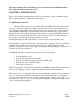
This Programming Guide is intended for use in conjunction with the EPSON Standard ESC/P Reference Manual (December 1997) CHAPTER 1 : INTRODUCTION This section of the Programming Guide will provide a technical overview of EPSON’s Stylus Photo 870 inkjet printer to facilitate driver development. 1.1 EPSON Stylus Photo 870 The Stylus Photo 870 is a six-color inkjet printer from EPSON. The Stylus Photo 870 is targeted for home photography uses.
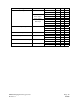
Table 1 EPSON Stylus Photo 870 Printer Feature Summary EPSON Stylus Photo 870 Print Head Interface (s) Printer Language Max Resolution (dpi) Selectable dot size Ink Type Ink Droplet Size 48 black nozzles 240 color nozzles, 48 nozzles x 5 (CcMmY).
CHAPTER 2 PAPER - TYPES, SIZES AND ORIENTATION MODE 2.
Paper Type Photo Paper Photo Quality Glossy Film Ink Jet Transparencies Photo Quality Adhesive sheet Iron-on Cool Peel Transfer Paper Photo Stickers EPSON Imaging Technology Center Revision: 1 Size Cut sheets Letter A4 Photo Paper (card) 113.6x175.
2.2 EPSON Paper Types and Orientation for the Stylus Photo 870 EPSON Stylus Photo 870 printer will print with portrait or landscape orientation as shown: Table 3 Paper Types and Orientation Orientation Paper Type Legal Letter A4 A5 A6 Executive Half Letter B5 Index card 5in. x8in. Index card 8in. x10in. Photo Paper 4 in. x 6 in.
CHAPTER 3 RECOMMENDATIONS The following recommendations are provided for development of printer drivers for the Stylus Photo 870 printer. The values provided are only starting recommendations. Adjustments to these values for different halftone modules may improve driver output quality. 3.1 Printing Mode Settings of the EPSON Stylus COLOR 460 The EPSON Stylus Photo 870 supports the following printing modes.
3.3 Black Ink Mode Setting Recommendations for the Stylus COLOR 870 Table 6 Black ink printing recommendations.
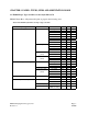
CHAPTER 4 PRINTABLE AREAS 4.1 Printable Area – Stylus Photo 870 The division of the paper between printing area and non-printing area is controlled by the values of A, B, C, D, E, G, and H, and by the dot unit (1 dot = 1/360 inch.). When printing near the top and bottom margins in MicroWeave, printing beyond the regions G and H below which the nozzles can project is not possibles. Table 7 Printable area diagram.
4.2 Printable Areas for Standard Size Papers Table 8 Standard Printable area values for A, B, D and E according to the printable area diagram. Legal Letter Executive Half Letter A4 A5 A6 B5 #10 Envelope DL Envelope C6 Envelope Envelope132 x 220 Postcard Return postcard Index card 5in.x 8in. Index card 8in.x 10in. Photo Paper 4x6 in.
CHAPTER 5 COMMAND SEQUENCE FLOW 5.1 Raster Graphics Modes The following three compression modes are available for raster graphics commands: 1) Non-compressed mode The print data is transferred without compression. This method is especially effective for printing data with low compression ratio, such as photographs. 2) RLL compression mode The print data is compressed using RLL (run-length limited) data compression.
5.2 Non-Compressed Mode & RLL Compression Mode Command Transfer Sequences Command setting procedure for non-compressed mode and RLL compression mode The basic commands and the sequence in which those commands are to be sent (for noncompressed mode and RLL compression mode) are shown below. Table 10 Command Setting Procedure of non-compressed and RLL compression mode for Stylus Photo 870 Transfer cycle By document Details of setting 1. Initial setting Items set 1.1 Set mechanism sequence 1.
5.
TIFF Compression Mode Command Transfer Sequences The following chart provides basic commands in proper sequence for TIFF compression mode. Table 11 Command sequences for TIFF Compression Mode By document 1. Initial settings 2. Printing method control By page By raster 3. Set print format (single sheet) 4. Enter compression mode 5. Set vertical position 6. Transfer data 7. Form feed 8. Terminate printing EPSON Imaging Technology Center Revision: 1 ESC (R SN ESC 00H 00H 00H ESC @ 1.
5.4 Roll Paper Mode Command Transfer Sequences The following chart provides basic commands in proper sequence for the roll paper mode. It displays the page format setting utilized with the ESC (c command for a top margin 0 setting. Refer to the explanation of the ESC (c command for further information. Table 12 Command sequences for Roll Paper Mode Transfer cycle By document Details of setting 1. Initial setting 2. Printing method control 3.
CHAPTER 6 INIDIVIDUAL COMMAND SPECIFICATIONS 6.1 Line feed “LF” Format: ASCII LF Hex 0A Decimal 10 Function: 1) Advances the printing position in the Y direction from the current one in the positive Y direction by an amount equal to the current line separation amount. Sets the printing position in the X direction to the starting point (the left margin position) on the X axis of the position management coordinate system.
6.2 Form feed “FF” Format: ASCII FF Hex 0C Decimal 12 Function: 1) The contents of the print buffer are printed, the position management coordinate system is set to the next page, and the printing position is set to the origin on this new position management coordinate system. In addition, if the next page does not exist, the paper is ejected. 2) With single sheet paper, this command is ignored if no paper is input.
6.3 Carriage return “CR” Format: ASCII CR Hex 0D Decimal 13 Function: 1) The printing position in the X direction is set to the origin (the left margin) on the X axis of the position management coordinate system.
6.4 Carriage return “ESC EM n” Format: ASCII ESC EM n Hex 1B 19 6E Decimal 27 25 110 Function: Sets controls for paper loading/ejecting Range of Values for Parameters: n=31H, 52H (="1", "R") Function: 1) 2) 3) 4) 5) Initial State: Control of the CSF (cut sheet feeder) is performed as follows, according to the value of n: n=31H select bin 1 n=52H eject paper If n has any value other than the above, this command is ignored. ESC EM R is only valid for paper which has been fed from the CSF.
6.5 Set absolute horizontal print position “ESC $ nL nH” Format: ASCII ESC $ nL nH Hex 1B 24 nL nH Decimal 27 36 nL nH Range of Values for Parameters: 0 ≤ nL ≤ 255 0 ≤ nH ≤ 127 Function: 1) The printing position in the X direction is set to a position spaced in the positive direction by (256 x nH + nL) x (absolute horizontal position setting units) inches from the origin (the left margin position) on the X axis of the position management coordinate system.
6.
6.7 Set page length in defined unit “ESC (C nL nH mL mH” Format: ASCII ESC ( C nL nH mL Hex 1B 28 43 nL nH mL Decimal 27 40 67 nL nH mL mH mH mH Range of Values for Parameters: nL=02H, nH=00H 0 < ( ( ( mH x 256 ) + mL ) x (page management units) ) ≤ 44 inches Function: 1) 2) 3) 4) The page length is set to (mH x 256 + mL) x (page management units) inches. If the values of mH and mL are outside the above ranges, this command is ignored.
6.8 Set page length in defined unit(extended) “ESC (C nL nH m1 m2 m3 m4” Format: ASCII ESC ( C nL nH m1 m2 m3 Hex 1B 28 43 nL nH m1 m2 m3 Decimal 27 40 67 nL nH m1 m2 m3 m4 m4 m4 Range of Values for Parameters: nL=04H, nH=00H 0<=(m4*1000000H+m3*10000H+m2*100H+m1) *1440/(defined unit) <=1FFFFFFFH Function: 1) The page length is set to (m4*256*256*256 +m3*256*256 + m2*256 + m1) x (page management units) inches.
6.9 Select graphics mode “ESC (G nL nH m” Format: ASCII ESC ( G nL Hex 1B 28 47 nL Decimal 27 40 71 nL nH nH nH m m m Range of Values for Parameters: nL=01H, nH=00H m=01H or 31H Function: 1) Shifts to graphics mode. 2) If m has any value other than the above, this command is ignored. 3) Printing of lines up to the present line is started, and the printer waits until the printing is completed. 4) The various settings are the same as when the power is turned on.
6.
6.
6.12 Set absolute vertical print position “ESC (V nL nH mL mH” Format: ASCII ESC ( V nL nH mL mH Hex 1B 28 32 nL nH mL mH Decimal 27 40 86 nL nH mL mH Range of Values for Parameters: nL=02H, nH=00H (Vertical position set) = (mL + mH x 256) x (units set) Function: 1) The printing position in the Y direction is set to a position spaced in the positive direction by (256 x mH + mL) x (the set absolute vertical position unit) inches from the origin upon the Y axis of the position management coordinate system.
6.
6.
6.
New lines generated by the LF command which go outside the printable area are affected. Processing by the ESC (v command is affected. Processing by the ESC (V command is affected. Commands related in the direction of receiving an effect (Operation) The page management units are set by the ESC (U command.
6.16 Select MicroWeave print mode “ESC (i” Format: ASCII ESC ( i 01H 00H n Hex 1B 28 63 01 00 n Decimal 27 40 105 1 0 n Range of Values for Parameters: n=00H, 01H, 30H, 31H Function: 1) Selects / deselects the MicroWeave mode. n=0 or 30H: deselects n=1 or 31H: selects Initial State: Non-MicroWeave mode Related Commands: Commands related in the direction of applying an effect (Setting) Changes the non-selected state set by the ESC (G command. Changes the non-selected state set by the ESC @ command.
6.17 Select dot size “ESC (e nL nH m d” Format: ASCII ESC ( e nL nH m d Hex 1B 28 65 nL nH m d Decimal 27 40 101 nL nH m d Range of Values for Parameters: nL=02H, nH=00H m=00H, d=00H, 01H, 02H, 03H, 04H, 10H Function: 1) The dot size is set according to the value of d. 2) The parameter has the following meaning: d=00H: default for a 360 dpi raster, Normal x3dot ………………for a 720 dpi raster, Normal x1,2 dot 3) The defaults are specific to each model of printer.
6.18 Select color “ESC (r nL nH m n” Format: ASCII ESC ( r nL nH m n Hex 1B 28 72 nL nH m n Decimal 27 40 114 nL nH m n Range of Values for Parameters: nL=02H, nH=00H m=00H,01H n=00H, 01H, 02H, 04H Function: 1) The print color is selected according to the values of m and n. m n Print color 00H 00H Black 00H 01H Magenta 00H 02H Cyan 00H 04H Yellow 00H 01H Light Magenta 00H 02H Light Cyan 2) If either m or n has a value other than those above, this command is ignored.
6.19 Set relative vertical print position “ESC (v nL nH mL mH” Format: ASCII ESC ( v nL nH mL mH Hex 1B 28 76 nL nH mL mH Decimal 27 40 118 nL nH mL mH Range of Values for Parameters: nL=02H, nH=00H (Relative vertical set position) = (mL + mH x 256) x (set units) Function: 1) The printing position in the Y direction is set to a position spaced in the positive direction from the present Y printing position in the Y direction by (256 x mH + mL) x (relative vertical position set unit) inches.
6.
6.21 Print raster graphics “ESC . c v h m nL nH d1...dk (c=0,1)” Format: ASCII ESC .
Run-length encoding compression mode In run-length encoding compression mode, the data is transferred in the following format. The data to be printed is always transferred in the format (counter) + (data). If 0 ≤ counter ≤ 127, then the data following the counter is non-compressed data, and the length of the compressed data is (counter)+1 bytes.
Related Commands: Commands related in the direction of applying an effect (Setting) None Commands related in the direction of receiving an effect (Setting) None Commands related in the direction of applying an effect (Operation) None Commands related in the direction of receiving an effect (Operation) None EPSON Imaging Technology Center Revision: 1 Page: 44 10/6/00
6.22 Enter TIFF compressed mode “ESC . 2 v h 1 0 0” Format: ASCII ESC . 2 v h 01H 00H 00H Hex 1B 2E 32 v h 01 00 00 Decimal 27 46 50 v h 1 0 0 Range of Values for Parameters: v=5, 10, 20 (v/3600 dpi) h=5, 10, 20 (h/3600 dpi) Function: 1) TIFF ver. 4.0 format raster graphics compression mode is set from this command until the command. 2) This supports the TIFF ver. 4.0 compression method.
Commands related in the direction of applying an effect (Operation) Only the following commands are valid: XFER CR MOVX EXIT MOVY MOVXBYTE COLR MOVXDOT Commands related in the direction of receiving an effect (Operation) The "unit" units are set by the ESC (U command.
6.
6.24 Set resolution of Raster image “ESC (D nL nH rL rH v h” Format: ASCII ESC ( D nL nH rL Hex 1B 28 44 nL nH rL Decimal 27 40 68 nL nH rL Range of Values for Parameters: nL=04H, nH=00H 0 <= v <= 127 0 <= h <=127 Function: 1) Set resolution of raster image ( ESC i ). Vertical resolution : v / ( rH*256 + rL ) inch Horizontal resolution : h / ( rH*256 + rL ) inch 2) Available resolution is 1/120, 1/180, 1/360, 1/720, 1/1440 inch 3) Following parameters are supported. 4) 0.
Commands related in the direction of receiving an effect (Setting) The Resolution setting of Raster image is returned to this initial states by the ESC @ and the ESC (G commands.
6.25 Transfer Raster image “ESC i r c b nL nH mL mH d1......dk” Format: ASCII ESC I r c b nL nH mL mH d1 d2…dk Hex 1B 69 r c b nL nH mL mH d1 d2…dk Decimal 27 105 r c b nL nH mL mH d1 d2…dk Range of Values for Parameters: r = 00H, 01H, 02H, 04H c = 00H, 01H b = 01H, 02H 0000H <= ( nH*256 + nL ) <= 7FFFH 0001H <= ( mH*256 + mL ) <= 7FFFH Function: 1) Prints dot graphics in raster format.
6.26 Initialize printer “ESC @” Format: ASCII ESC @ Hex 1B 40 Decimal 27 64 Range of Values for Parameters: Function: 1) The various settings are returned to their initial values. 2) The page management coordinate system and the position management coordinate system are set by taking the origin upon the Y axis as the present printing position on the Y axis. 3) The present printing position on the X axis is set to the origin upon the X axis. 4) The text mode is selected.
6.27 Turn unidirectional mode on/off “ESC U n” Format: ASCII ESC U n Hex 1B 55 n Decimal 27 85 n Range of Values for Parameters: n=00H, 01H, 02H, 30H, 31H, 32H Function: 1) The printing direction is selected according to the value of n in the following manner: n=00H or 30H: selects bi-directional printing n=01H or 31H: selects unidirectional printing n=02H or 32H: selects automatic printing direction control 2) If n has any value other than the above, this command is ignored.
6.28 Set relative horizontal print position “ESC \ nL nH” Format: ASCII ESC \ nL nH Hex 1B 5C nL nH Decimal 27 92 nL nH Range of Values for Parameters: (nL + 256 x nH) x (set units) inches Function: 1) If bit 6 of nH is 1, this is taken as meaning that a negative value has been set, and it is considered that the MSB of nH is 1. Negative values are expressed in two's complement.
6.29 Set relative horizontal print position “ESC (/ nL nH n1 n2 m1 m2” Format: ASCII ESC ( / nL nH n1 n2 m1 m2 Hex 1B 28 2F nL nH n1 n2 m1 m2 Decimal 27 40 47 nL nH n1 n2 m1 m2 Range of Values for Parameters: nL=04H, nH=00H 0 <= (m4*1000000H +m3*10000H + m2*100 + m1))×(relative horizontal print position set unit)inch <= 11904/1440inch or If bit 7 of m4 is 1,this is taken to mean that a negative value has been set. Function: 1) If bit 7 of m4 is 1, this is taken as meaning that a negative value has been set.
6.30 Select printing color “ESC r n” Format: ASCII ESC r n Hex 1B 72 n Decimal 27 114 n Range of Values for Parameters: 00H ≤ n ≤ 06H Function: 1) The printing color is selected according to the value of n, as follows: if n=0: black if n=1: magenta if n=2: cyan if n=4: yellow 2) If n has a value other than the above, this command is ignored. Initial State: Black selected.
6.31 Extended Raster Graphics Specific Commands-Binaray Mode Commands for“ESC .2” Format: B (Command byte) Range of Values for Parameters: Function: 1) The internal commands fall into two groups.
* The remaining four least significant bits are the parameter embedded in the command byte (unsigned). If the parameter has a value of from 0 to 15, it can be embedded in the command byte. When the parameter extension bit is 1, parameter bytes follow up to a maximum of 15 bytes.
6.32 Select printing color “” Format: <1000xxxx>B Range of Values for Parameters: 10000000B, 10000001B, 10000010B, 10000100B, 10001001B, 10001010B Function: 1) Each parameter sets the color for the raster data: 10000000B: black 10000001B: magenta 10000010B: cyan 10000100B: yellow Combinations of colors are not allowed. 2) The printing position in the X direction is set to the origin upon the X axis.
6.33 Carriage return to left-most print position “” Format: <11100010>B Range of Values for Parameters: Function: 1) The printing position in the X direction is set to the origin upon the X axis.
6.34 Exit TIFF compressed mode “” Format: <11100011>B Range of Values for Parameters: Function: 1) Terminates compressed mode. 2) The raster data remaining in the printer is all printed. 3) The printing position in the X direction is set to the origin upon the X axis. Initial State: Related Commands: Commands related in the direction of applying an effect (Setting) The TIFF ver. 4.0 compression mode set by the ESC .2 command is terminated.
6.35 Set relative horizontal position “” Format: <010Fxxxx>B Range of Values for Parameters: If F=0: -8 ≤ parameter ≤ 7 If F=1: counter value=1, 2 Parameter=n1 or n1 + n2 x 256 Function: 1) The parameter shows the relative signed horizontal position from the current printing position in the X direction. The units may be specified as byte or dot units with the or command respectively. Directly after the input of the ESC .2 command, is designated.
6.36 Set unit to 8 dots ” Format: <11100100>B Format: <11100100>B Range of Values for Parameters: Function: 1) The unit set by the ESC (U command is taken as standard, and 8 times that unit is taken as 1 unit for the MOVX command. 2) The printing position in the X direction is taken as the origin upon the X axis. Initial State: is set.
6.37 Set unit to 1 dot ” Format: <11100101>B Range of Values for Parameters: Function: 1) The unit set by the ESC (U command is taken as standard, and that unit is taken as 1 unit for the MOVX command. 2) The printing position in the X direction is taken as the origin upon the X axis. Initial State: is set.
6.38 Set relative vertical position < MOVY >” Format: <011Fxxxx>B Range of Values for Parameters: If F=0: 0 ≤ parameter ≤ 15 (dot units) If F=1: counter value=1, 2 Parameter=n1 or n1 + n2 x 256 (dot units) Function: 1) The parameter shows the relative unsigned vertical position from the current printing position in the Y direction. 2) The printing position in the Y direction is set to (the present position) + (the set displacement position).
6.39 Transfer raster graphics data < XFER >” Format: <001Fxxxx>B (n) d1, ..., dn Range of Values for Parameters: If F=0: 0 ≤ number of data items ≤ 15 If F=1: counter value = 1, 2 The number of data items = n1 or n1 + n2 x 256 0 ≤ d1, ..., dn ≤ 255 F=0: The four least significant bits show the total number of bytes of compressed data in TIFF ver. 4.0 format. F=1: The four least significant bits show the number of counter bytes of compressed data. Function: 1) The meaning of the parameter is shown below.
6.40 EPSON packet mode exit command (special command)”0 0 0 ESC 1 @EJL 20H 1284.4 0AH @EJL 20H 20H 20H 20H 20H 0AH” Format: ASCII 00H 00H 00H ESC 01H @EJL 20H 1284.
6.41 Enter Remote Mode ESC "(R" 08H 00H 00H "REMOTE1 Format: ASCII ESC ( R 08H 00H 00H R E M O T E 1 Hex 1B 28 52 08 00 00 52 45 4D 4F 54 45 31 Decimal 27 40 82 8 0 0 82 69 77 79 84 69 49 Function: * The present emulation mode is terminated, and enter remote mode. * The remote mode is continued until the remote mode terminate command is received. * Print data present in the buffer at the time point that this command is received is printed before enter the remote mode.
6.
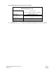
Depending on the paper size and the type of paper used, the EPSON Stylus Photo 870 printer should receive SN command values for paper feeding as displayed in the following tables: Table 13 Values for 2nd paramter when 1st parameter is 00H (Paper feed mode) in the SN command.
Table 14 Values for 2nd parameter when 1st parameter is 01H (Paper gap mode) in the SN command.
Function: * * * Changes the mechanical sequence for the default environment to the value specified by m1 and m2. If the parameter is out of range (03H - FFH), this command is ignored, and the previous setting is maintained. This command is only valid in remote mode.
6.
Set Roll Paper Mode “EX" 06H 00H 00H 00H 00H 00H 05H m1 Format: ASCII E X 06H 00H 00H 00H 00H 00H 05H m1 Hex 45 58 06 00 00 00 00 00 05 m1 Decimal 69 88 6 0 0 0 0 0 5 m1 Parameters: * The parameter m1 is a one byte binary format parameter, and this select the roll paper mode as follows: m1 00H 01H 02H to FFH Function: * * * Roll Paper Mode Off On Reserved Changes the roll paper mode the default environment to the value specified by m1.
6.44 Terminate Remote Mode ESC 00H 00H 00H Format: ASCII ESC 00H 00H 00H Hex 1B 00 00 00 Decimal 27 0 0 0 Function: Copies the default environment to the current setting. Executes the ESC “@” command in ESC/P2. (Execute software initialization.) Exits from Remote mode and enters to the mode of the selected printer control language.