EPSON COLOR INK-JET PRINTER EPSON Stylus Color 600 SERVICE MANUAL SEIKO EPSON CORPORATION 4007367
NOTICE All rights reserved. Reproduction of any part of this manual in any form whatsoever without SEIKO EPSON’s express written permission is forbidden. The contents of this manual are subjects to change without notice. All efforts have been made to ensure the accuracy of the contents of this manual. However, should any errors be detected, SEIKO EPSON would greatly appreciate being informed of them.
PRECAUTIONS Precautionary notations throughout the text are categorized relative to 1) personal injury and 2) damage to equipment. WARNING Signals a precaution which, if ignored, could result in serious or fatal personal injury. Great caution should be exercised in performing procedures preceded by WARNING Headings. CAUTION Signals a precaution which, if ignored, could result in damage to equipment.
PREFACE This manual describes functions, theory of electrical and mechanical operations, maintenance, and repair of EPSON Stylus Color 600. The instructions and procedures included herein are intended for the experience repair technician, and attention should be given to die precautions on the preceding page. The Chapters are organized as follows: CHAPTER 1. GENERAL DESCRIPTION Provides a general product overview, lists specifications, and illustrates the main components of the printer. CHAPTER 2.
REVISION SHEET Revision Issued Data Contents Rev.
TABLE OF CONTENTS CHAPTER 1. CHAPTER 2. CHAPTER 3. CHAPTER 4. CHAPTER 5. CHAPTER 6.
Chapter 1 Product Descriptions 1.1 Features ................................................................................................................ 1-1 1.2 Specifications....................................................................................................... 1-2 1.2.1 Printing Specification ....................................................................................................... 1-2 1.2.2 Paper Specification ..............................................................
Chapter 1 Product Description 1.1 Features EPSON Stylus Color 600 is designed for low price for that high performance.
EPSON Stylus Color 600 1.2 Specifications This section describes the product specifications for EPSON Stylus Color 600. 1.2.
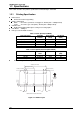
Chapter 1 Product Description Paper Feeding Method Friction feed with built in ASF (Auto Sheet Feeder) Line Spacing 1/6 inch or programmable at 1/360 inch Paper Path Top entry (from ASF) only Feeding Speed 66.6 ms (at 1/6 inch line-feed) 3.0 inch/sec (76.
EPSON Stylus Color 600 Control Code ESC/P2 and expanded raster graphics code EPSON Remote command Character Tables Legal and 14 international character sets Standard version: 11 character tables (See Table 1-4 for details) NLSP version: 19 character tables (See Table 1-4 for details) Typeface *1 Bit map LQ font: Scaleable font: EPSON Roman EPSON Sans Serif EPSON Courier EPSON Prestige EPSON Script (10/12/15 CPI, Proportional) (10/12/15 CPI, Proportional) (10/12/15 CPI) (10/12/15
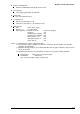
Chapter 1 Product Description 1.2.2 Paper Specification This section describes the types of paper that can be used in this printer. 1.2.2.1 Cut Sheet [Size] :A4 [Width 210mm (8.3”) x Length 297mm (11.7”)] :Letter [Width 216mm (8.5”) x Length 279mm (11.0”)] :B5 [Width 182mm (7.2”) x Length 257mm (10.1”)] :Legal [Width 216mm (8.5”) x Length 356mm (14.0”)] :Half Letter [Width 139.7mm (5.5”) x Length 215.9mm (8.5”)] :Exclusive [Width 190.5mm (7.
EPSON Stylus Color 600 1.2.3 Adjust Lever Settings (PG adjust lever) The adjust lever located on the right side (blue knob) under the printer cover needs to be set to the proper position according to the paper you print (Refer to the table below). Also, if there is any dirt caused by friction on the wavy or wrinkled paper, this can be prevented by changing the lever position to rear position (marked with “+”) in spite of paper types. Table 1-5.
Chapter 1 Product Description 1.2.4 Printable Area 1.2.4.1 Cut Sheet Following tables show printable areas at Character mode and Raster Graphics mode. Table 1-6. Character Table PL (Paper Length) (typ.) A4 210mm(8.3”) 297mm(11.7”) Letter 216mm(8.5”) 279mm(11.0”) B5 182mm(7.2”) 257mm(10.1”) Legal 216mm(8.5”) 356mm(14.0”) Statement 139.7mm(5.5”) 215.9mm(8.5”) Executive 190.5mm(7.5”) 254mm(10”) Paper size PW (Paper width) (typ.) LM (Left margin) (min.) 3mm(0.12”) 3mm(0.12”) 3mm(0.12”) 3mm(0.12”) 3mm(0.
EPSON Stylus Color 600 1.2.4.2 Envelope The table and figure below show the printable area for envelopes. Table 1-8. Envelope Paper Size LM (Left Margin) (min.) 3mm (0.12”) 3mm (0.12”) 3mm (0.12”) #10 DL C6 RM (Right Margin) (min.) 28mm (1.10”) 7mm (0.28”) 3mm (0.12”) TM (Top Margin) (min.) 3mm (0.12”) 3mm (0.12”) 3mm (0.12”) BM (Bottom Margin) (min.) 14mm (0.55”) 14mm (0.55”) 14mm (0.55”) RM LM TM Printable area BM Figure 1-4. Printing Area for Envelope 1-8 Rev.
Chapter 1 Product Description 1.2.5 Environmental Condition Temperature Operating Non-operating :10 - 35•• (Refer to the figure below for condition) :-20 - 60•• (with shipment container) Note) Storage should be within one month at 40°C and 120 hours at 60°C. Humidity Operating :20% - 80% RH (without condensation.
EPSON Stylus Color 600 1.2.6 Ink Cartridge Specifications 1.2.6.1 Black Ink Cartridge Table 1-9.
Chapter 1 Product Description 1.2.6.2 Color Ink Cartridge Table 1-10.
EPSON Stylus Color 600 1.2.7 Physical Specification [Dimension] :429mm(W) x 234mm(D) x 162mm(H) :429mm(W) x 695mm(D) x 309mm(H) with extended stacker and paper support. [Weight] :5.2Kg 695mm (Max) 309mm 429mm Figure 1-8. Dimension 1-12 Rev.
Chapter 1 Product Description 1.2.8 Electric Specification [120V] Version [Rated voltage] [Input voltage range] [Rated frequency range] [Input frequency range] [Rated current] [Power consumption] [220•`240V] Version [Rated voltage] [Input voltage range] [Rated frequency range] [Input frequency range] [Rated current] [Power consumption] 1.2.9 [Insulation Resistance] [Dielectric strength] [Insulation Resistance] [Dielectric strength] :AC120V :AC103.
EPSON Stylus Color 600 1.2.
Chapter 1 Product Description Rev. A Bit image: Bit Image :ESC* Graphics: Graphics Mode Raster Graphics Microweave control Dot size control Horizontal Position Printing Speed :ESC (G :ESC.
EPSON Stylus Color 600 1.3 Interface This printer provides both parallel and serial interface as standard. 1.3.
Chapter 1 Product Description 1.3.
EPSON Stylus Color 600 Following lists “Notes” when using Parallel Interface. “Return GND pin” in the table means twist pair return and is used for all control signals except for Logic H,+5V, Chassis, GND and NC. In this twist pair return, returning side is connected to GND (16,33, 19-30 pin) for twist pair return. Also, these cables are shielded wires and it is effective to connect to each chassis GND in the PC and printer for electrostatic noise.
Chapter 1 Product Description [Signal level: TTL compatible (IEEE-1284 level 1 device)] Table 1-16. Signal Level Parameter Minimum Maximum Condition VOH* --5.5V VOL* -0.5V --IOH* --0.32mA VOH = 2.4V IOL* --12mA VOL = 0.4V CO --50pF VIH --2.0V VIL 0.8V --IIH --0.32mA VIH = 2.0V IIL --12mA VIL = 0.8V CI --50pF Note) *: A low logic level on the Logic H signal is 2.0V or less when the printer is powered off and this signal is equal or exceeding 3.0V when the printer is powered on.
EPSON Stylus Color 600 1.3.3 Serial Interface [Standard] [Synchronization] [Bit Rate] [Handshaking] [Word Format] [Connector] [Recommended Cable] :Based on RS-423 :Synchronous :Approx. 900Kbps :X-ON/X-OFF, DTR Protocol :Data Bit = 8 bits :Parity Bit = None :Start Bit = 1 bit :Stop Bit = 1 bit :8-pin mini-circular connector :Apple System Peripheral-8 Cable (Part #: M0197) Table 1-17. Pin Assignment Pin No.
Chapter 1 Product Description 1.4 Control Panel Since EPSON Stylus Color 600 does not require many buttons since printer driver can start various settings and motions. Therefore, there are only 2 non-lock type push switches, 1 lock type push switch and 4 LEDs. Following figure shows control panel of EPSON Stylus Color 600. Power LED Paper out LED Ink out(Black)LED Ink out(CMY)LED Cleaning Switch (Ink maintenance) Load/Eject switch Power switch Figure 1-11. Control Panel 1.4.
EPSON Stylus Color 600 1.4.2 Panel Functions •q Panel Functions •r Table 1-19. Panel Function Switch Load/Eject (Pushing within 0.5 seconds*) Function Loads or Eject the paper. When the carriage is on the Ink Cartridge change position, return the carriage from Ink Cartridge change position. Load/Eject Starts the Ink Cartridge change sequence.** (Pushing for 2 seconds*) Moves the carriage to cartridge change position. Cleaning Starts the Head Cleaning sequence.
Chapter 1 Product Description By performing a particular setting mode, Maintenance error can be cleared and certain addresses of EEPROM can also be reset. Maintenance Error Clear [Step 1] [Step 2] Turn the printer on while holding down Load/Eject and Cleaning switches at the same time. (By operating this performance, the Paper Out LED starts blinking.) Push the Load/Eject switch while the Paper Out LED is blinking (5 seconds). Following shows the lists that will be cleared by this performance.
EPSON Stylus Color 600 1.5 Error Status When following status occur, the printer goes to the error status and stops taking data, setting the /ERROR signal in the interface as “Low”, and Busy signal as “High”. At this time, the printer goes to non printable status. Refer to section 1.4.2 for more details of LED Panel indicators during the various error status. 1.5.1 Ink Out When the printer runs out the most part of the ink of any one color, it warns ink-low and keeps printing.
Chapter 1 Product Description 1.5.4 No Ink-Cartridge Error Following reasons can be the causes when printer goes this error mode. When the printer is turned on for the first time. (This is a normal error state and it returns to the normal state after installing an ink cartridge according to the ink cartridge exchange operation.) Ink cartridge exchange operation is done correctly.
EPSON Stylus Color 600 1.6 Printer Initialization EPSON Stylus Color 600 has three kinds of initialization methods. Following explains each initialization. Power-on initialization This printer is initialized when turning the printer power on, or printer recognized the cold-reset command (remote RS command). When printer is initialized, following action is performed. Initializes printer mechanism. Clears input data buffer. Clears print buffer. Sets default values.
Chapter 1 Product Description 1.7 Main Components EPSON Stylus Color 600 has following major units. Also, it is one of the major characteristics that the bottom of the Printer mechanism plays the role as lower case at the same time. 1.7.
EPSON Stylus Color 600 1.7.2 C200 MAIN Board The C200 MAIN board controls whole mechanism operations and a data processing operation. Most of the functions of the circuit are integrated into single ASIC; E05B43YA (IC2) and this makes the board design very simple and reliable. IC7 Printhead Driver IC15 PF Motor Driver IC14 CR Motor Driver IC2 ASIC (E05B43YA) IC1 CPU (TMP95C0618F) Parallel I/F(CN1) IC5 DRAM(4MBit) Serial I/F (CN2) IC3 PROM(4MBit) IC6 Mask ROM (CG) Lithium Battery Figure 1-13.
Chapter 1 Product Description 1.7.3 C206 PSB/PSE Board The C206 PSB/PSE board is a switching regulator type power supply unit and constantly supplies stable logic and power voltages to the printer mechanism and the main control board. Also, since this C206 PSB/PSE board has the power switch in the secondly side of the circuit, it is possible to keep supplying electricity to the C200 MAIN control board for 30 seconds even after the power switch is turned off.
Chapter 2 Operating Principles 2.1 OVERVIEW ............................................................................................................2-1 2.1.1 Printer Mechanism ............................................................................................................ 2-1 2.1.1.1 Printing Mechanism .............................................................................................. 2-2 2.1.1.1.1 Printing Process...................................................................
Chapter2 Operating Principles 2.1 OVERVIEW This section describes Printer Mechanism, electric circuit board (C206 PSB, C200 Main, C206PNL board) of Stylus Color 600. 2.1.1 Printer Mechanism Unlike previous EPSON Ink Jet printers, printer mechanism of Stylus Color 600 does not have exclusive mechanism to change over paper feeding and Pumping operation. In stead, this control is done by the turning direction of paper feed/pump motor and position of carriage at that time.
EPSON Stylus Color 600 2.1.1.1 Printing Mechanism Basic principles of the print head which plays major role of printing mechanism is the same as previous models; on demand type MACH head method, but there is some difference in the resolution.
Chapter2 Operating Principles 2.1.1.1.1 Printing Process Following figures indicate the sectional drawing of normal state and ejecting state of print head. (1) Normal State: When the print signal is not output, PTZ also does not move in the waiting state(normal state). Ink Course PZT Nozzle Cavity Nozzle Plate Figure 2-3.
EPSON Stylus Color 600 2.1.1.1.2 Printing Method This section explains printing method of actual printing such as printing text at various resolution select/printing mode and graphics printing. In order to prevent white or color banding which are peculiar problem of ink-jet, new Micro-Weave functions are added to the previous Micro-Weave function. The number of nozzles and printing mode according to the selected resolution are used separately by a user.
Note2) Chapter2 Operating Principles Two groups which are divided according to each elements will be divided either even dot or odd dot when particular lines(level direction line) are formed and eventually, these lines will be completed at selected resolution. Following is a conceptual figure when full overlap microweave orms a particular line. Nozzle No.#9 Condition: 360-dpi printing Nozzle: Total 10 nozzle/each color Nozzle No.#4 Particular line(Completed line) 360-dpi Figure 2-5.
EPSON Stylus Color 600 The difference between Full-Overlap Micro-Weave and Part line Overlap Micro-Weave are following; Full-Overlap Micro-Weave: Printing is performed, judging if nozzles are even or odd dot by 2 different dots with all different rasters. Part line Overlap Micro-Weave: After particular nozzles(only#1, and #6 in the figure2-7) are determined as overlap nozzles, even or odd dot will be determined like Full-overlap Micro-Weave does.
Chapter2 Operating Principles 2.1.1.2 Carriage Mechanism Carriage mechanism is to drive the carriage with print head mounted from left to right or vice versa. The carriage drive motor in this printer is a 4-phase, 200-pole, stepping motor and is driven by 1-2phase, 2-2phase and W1-2phase drive method.
EPSON Stylus Color 600 The table below shows W1-2 phase drive sequence at each steps when the rotor of carriage motor makes one rotation. In the Stylus Color 600, in addition to a function that printing is performed with W1-2 drive phase, high speed skip mode which is a function to skip over the blank from the end of the printing data to the next data starting point with high seed can be also performed by 2-2 and 1-2 phase drive.
Chapter2 Operating Principles The figure below shows carriage mechanism. The print head as a core of the printing mechanism is stored in the carriage unit. This print head keeps the tilt of print head in flexible and adjustable structure by moving the adjustment lever up and down by the tilt adjustment mechanism.
EPSON Stylus Color 600 2.1.1.2.1 Platen Gap Adjust Mechanism and Parallel adjustment Mechanism This mechanism can be set by the users and can prevent various problems related to low image density or print with any dirt by changing the positions of PG lever according to the paper types. Paper Normal paper, Coated paper Envelops Table 2-6. Platen Gap Adjust Lever Setting Lever position PG adjustment value Front 0 mm (1.1mm between head and platen) Rear 0.9mm (2.
Chapter2 Operating Principles 2.1.1.3 Paper Feed Mechanism and Pump Mechanism Mechanisms that send the paper in the hopper to inside the printer and perform constant paper feed in order to perform printing on the sent paper are called paper feed mechanism as generic name. In the Stylus Color 600, 4-phase, 200-pole hybrid type pulse motor is used in the PF motor as a motive power of the paper mechanism and driving is done at 2-2 and 1-2 phase drive method.
EPSON Stylus Color 600 Papers on the ASF (auto-sheet-feeder) supplied by the user are carried to the printer inside by paper pick up sequence. Unlike the previous models, ASF of Stylus Color 600 has mufti feed prevention mechanism. Following explains this function and figure below shows its mechanism. [1. Multi feed prevention mechanism] When the Load/Eject button is pressed, reversed rotation of PF motor is performed.
Chapter2 Operating Principles In the paper pick up mechanism of Stylus Color 600, same mechanism as Stlylus Color IIs/820 are applied. This mechanism changes adjoined lines of gear by colliding trigger lever with carriage unit and convey the motive power on the platen to the ASF side(paper roller). The figure below shows mechanism with explanation. [2.
EPSON Stylus Color 600 2.1.1.4 Ink System Ink system mechanism consists of 1)cap mechanism, 2)pump mechanism, 3)carriage lock mechanism, 4)waste ink absorber and 5)ink sequence. Out of these mechanism, from 1) to 4) are physical mechanism and parts which are mounted on the printer mechanism and 5) ink sequence is performed automatically by firmware.
Chapter2 Operating Principles 2.1.1.4.1 Pump, Carriage Lock, Head Cleaner Mechanism In the Stylus Color 600, there is no switch or mechanism to change over the pump/paper feed mechanism. Therefore, whenever the paper feed/pump motor rotate, pump drive roller in the pump unit inside rotates. However, ink absorption/non ink absorption are separated by the roller rotational direction.
EPSON Stylus Color 600 The table below shows PF/Pump motor rotational direction and pump system operation. Table 2-11.
Chapter2 Operating Principles 2.1.1.4.2 Cap Mechanism In the cap mechanism, in order to prevent ink from being thickened on the head surface, it is controlled that the head surface stays adherent to the rubber frame of the cap surface when the power is off. The absorber is spread in the cap and can hold a certain amount of ink which is absorbed from the head without draining it to the waste ink pad.
EPSON Stylus Color 600 2.2 Electrical Circuit Operating Principles Stylus Color 600 contains the following four electric circuit boards. C206 PSB/PSE board C200 Main board Head Driver board C206 PNL board C206 PSB/PSE, C200 board are explained in this section. The head drive board is installed in the head uniton the carriage. The figure below shows major connection of the 3 boards and their roles.
Chapter2 Operating Principles 2.2.1 C206 PSB/PSE Power Board C206 PSB/PSE board is a power supply board with a RCC switching regulator, which generates +42VDC for drive part and +5VDC for logic part to drive the printer. One of the major characteristic of this board is that the same secondary switch is used as Stylus Color series printer.
EPSON Stylus Color 600 DB1 Full Wave Rectifier circuit L1,R1-R2 T1 C11 C1-C4 Filter Circuit Prevention of current flow +42VDC Q1 T R A N S Main switching circuit Q2,Q3, F1 D51 Smoothing circuit C51 Smoothing circuit +5V generation circuit (IC51) +42V constant voltage control circuit C84,Q84 Power OFF Delay circuit Q31,PC1 ZD81-86, ZD51 Feedback circuit +5VDC ZD52,87 +42V overvoltage protection circuit ZD53 +5V overvoltage protection circuit PSO Signal PC1 Photo coupler AC100V Figu
Chapter2 Operating Principles 2.2.2 C200 Main Board Various DC voltage generated on the C206 PSB/PSE board is added various signals in order to drive the printer function on the C200 main board, and the drive of CR/PF(Pump) motor and printing head is performed. This control board consists of system part and drive part.
EPSON Stylus Color 600 Timer Data: The timer IC that uses lithium battery as power source monitors how long the power is off. When the power is turned on, it is changed to appropriate cleaning level according to the time that the power is off. Serial Data: The gate array receives serial data through the transceiver IC.
Chapter2 Operating Principles 2.2.2.1 Reset Circuits The reset circuit prevents the CPU from running away, which is caused by the unstable voltage in the logic line during the power ON/OFF. Also, this circuit monitors level of power voltage at the overloading or malfunction on the circuit and manages the printer to operate normally, keeping the damage to the printer minimum during the abnormal situations.
EPSON Stylus Color 600 2.2.2.2 Sensor Circuits The following sensor circuits are mounted in the Stylus Color 600 and selects appropriate operations based on the returned information. ASF Sensor: (Photo) An ASF sensor detects the position of return lever when the power is turned on, and causes the paper to be picked up by the pick up roller from the normal initial condition. (Refer to section 2.1.1.3 for detail.) PE Sensor: (Photo) A PE sensor determines if there is paper in the printer.
Chapter2 Operating Principles 2.2.2.3 EEPROM Control Circuits The EEPROM of Stylus Color 600 has following contents. Gate array E05B43(IC2) controls operations of reading data when the power is on and writing data when the power is off. Ink consumption(Bk, CMY) CL counter(Various cleaning operations that are previously done are memorized) Destination information Information of various adjustment values(Bi-D, VH voltage, etc.
EPSON Stylus Color 600 2.2.2.4 Timer Circuit The lithium battery is mounted on the C200 main board and calculates how long the printer is not in used. The timer IC(IC10) starts counting with oscillation motivated by the CR3 using this battery as a power source. The figure below shows connection of the Timer circuit. +5V BAT1 D1 D4 8 2 CR3 3 4 VDD CS 1 XOUT XIN /SCK 6 VSS SIO 7 S-3510ANFJ (IC10) E05B43(IC2) 125 TCE 122 TIO 123 TCLK 126 TDATA +5V Figure 2-23.
Chapter2 Operating Principles 2.2.2.6 Print Head Control Circuit The print head control circuit of Stylus Color 600 has following characteristics. Common waveform circuit became one HIC. Micro-vibration mode is added.(when the CR motor is accelerating) High speed drive 14.4KHz (trapezoidal wave form Enhanced Nozzle configuration (resolution in the vertical direction)90dpi (However, black nozzle is 2 lines structure) Also, Stylus Color 600 has Micro-dot control as dot shooting control.
EPSON Stylus Color 600 [Nozzle Selector Drive Circuit] In order to motivate the print head to carry out printing, it is necessary to transmit the print data to the appropriate nozzles, which becomes direct signals to drive PZT. This data transmission is performed by the serial transport method, however the data output for each black and CMY head is transmitted by the parallel method. The figure below shows data transmission circuit.
Chapter2 Operating Principles After the data transmission by the nozzle selector(IR2C72C, IR2C73C) is completed and a certain time passes, trapezoidal wave form generated by the common drive circuit once sends electric current to the PZT for the proper nozzles which are determined in the nozzle selector circuit. This motivates PZT and ejects the ink in the cavity. The figure below shows normal dot data transmission timing in order to from 1-dot.
EPSON Stylus Color 600 2.2.2.7 PF(Pump) Motor Drive Circuit IC15(UDN2917) is used for driving PF(Pump) motor. In the IC, Bi-pola drive PWM current control type is performed, making it possible to provide stable current to each phase of motor. Also, it makes possible to change over the reference voltage as drive current settings by making 3 combinations(100%,66% and 33%), using 4 current setting ports(input). (Refer to 2.1.1.
Chapter2 Operating Principles 2.2.2.8 CR Motor Drive Circuit In the CR motor, the same UPD2917(IC14) as the PF motor has used. In the IC, Bi-pola drive PWM current control type is performed, making it possible to provide stable current to each phase of motor. Also, it makes possible to change over the reference voltage as drive current settings by making 3 combinations(100%, 66% and 33%), using 4 current setting ports(input). (Refer to 2.1.1.
Chapter 3 Disassembly and Assembly 3.1. OVERVIEW ...........................................................................................................3-1 3.1.1. Precautions for Disassembling the Printer..................................................................... 3-1 3.1.2. Specification for Screws.................................................................................................. 3-2 3.1.3. Tools ...................................................................................
Chapter 3 Disassembly and Assembly 3.1 OVERVIEW This section describes procedures for disassembling the main components of EPSON Stylus Color 600. Unless otherwise specified, disassembly units or components can be reassembled by reversing the disassembly procedure. Therefore, no assembly procedures are included in this section. Precautions for any disassembly or assembly procedure are described under the heading “WORK POINT”.
EPSON Stylus Color 600 Service Manual 3.1.2 Specification for Screws Table 3-1 lists the abbreviation of screws and its use. Refer to the screw number in the following table to identify the type of screw shown in the disassembly procedures. Table 3-1. Screw Identification Table No. 1 Shape Name CBS (Cross/Bind/S-tight screw) 2 M3x10 3 CBP (Cross/Bind/P-tight screw) 4 M3x6 M3x10 5 6 CP (Cross/Pan-head screw) 7 3.1.
Chapter 3 Disassembly and Assembly 3.1.4 Work Completion Check If any service is made to the printer, use the check list shown below, to confirm that all works are completed properly and the printer is ready to return to the user. Category Item Self-Print Test Online Print Test Printhead Carriage Mechanism Main Unit Paper Feeding Mechanism Adjustment Lubrication Specified Adjustment Specified Point System Packing ROM Version Ink Cartridge Protective Materials Other Rev.
EPSON Stylus Color 600 Service Manual 3.2 DISASSEMBLY AND ASSEMBLY This section describes the step-by-step disassembly procedures shown in the diagram below. Housing Removal Section 3.2.1 Circuit Boards Removal Section 3.2.2 Printer Mechanism Disassembly Seciton 3.2.5 Control Panel Removal Section 3.2.3 Printhead Removal Section 3.2.5.1 Waste Ink Pad Assembly Removal Section 3.2.4 Pump/Cap Assembly Removal Section 3.2.5.2 CR Motor Assembly Removal Section 3.2.5.3 PF Motor Assembly Removal Section 3.
Chapter 3 Disassembly and Assembly 3.2.1 Housing Removal Since the EPSON Stylus Color 600 has no lower housing as previous EPSON printers, the printer mechanism can be taken out by only removing the upper housing. 1. 2. Open the printer cover and set the PG adjust lever on the right-hand side to (+) position. Remove 4 screws (No.2) and remove the upper housing. WORK POINT Pull the front end of the upper housing while lifting up the upper housing to remove it.
EPSON Stylus Color 600 Service Manual 3.2.2 Circuit Boards Removal The electric circuit boards of the printer (Main control circuit board: C200 MAIN / Power supply circuit board: C206 PSB/PSE) are both installed on single metal chassis and attached to the printer mechanism. Therefore, first detach the metal chassis from the printer mechanism to remove the electric circuit boards. 1. 2. Remove the upper housing (Refer to section 3.2.1) Remove 5 screws (No.
Chapter 3 Disassembly and Assembly MAIN Board (C200 MAIN) Power Supply Board (C206 PSB/PSE) SHIELD PLATE, M/B Figure 3-4. Circuit Boards Removal REQUIRED ADJUSTMENT Be sure to perform the following adjustments when the C200 MAIN board is replaced: 1) VH Voltage value writing (Refer to Chapter 4 / Section 4.2.2.3.) 2) Printhead Angle Adjustment (Refer to Chapter 4 / Section 4.2.2.4.) 3) Bi-D Alignment Adjustment (Refer to Chapter 4 / Section 4.2.2.5.) Rev.
EPSON Stylus Color 600 Service Manual 3.2.3 Control Panel Removal 1. Remove the upper housing (Refer to Section 3.2.1) 2. Remove 2 screws (No.1) and remove the control panel assembly from the printer mechanism and disconnect the flat cable from the connector of the panel assembly. WORK POINT By removing the control panel assembly, the stacker assembly is also detached from the printer mechanism as it held by the control panel assembly.
Chapter 3 Disassembly and Assembly 3.2.4 Waste Ink Pad Assembly Removal 1. Removing the upper housing (Refer to section 3.2.1) 2. Removing the control panel assembly (Refer to section 3.2.3) 3. Remove 1 screw (No.4) at the right-hand side of the printer mechanism, that fixing “Waste Ink Pad Assembly”. 4. Remove “SPACER, TRAY” fixing “Waste Ink Pad Assembly” at the left-hand side of the printer mechanism and remove “Waste Ink Pad Assembly” by pulling it downward.
EPSON Stylus Color 600 Service Manual 3.2.5 Disassembling the Printer Mechanism This section describes the procedures for removing the main components consisting the printer mechanism. 3.2.5.1 Printhead Removal 1. Removing the upper housing. (Refer to section 3.2.1) 2. Rotate “Gear, 67.2” (largest gear at the left-hand side of the printer mechanism) toward the front to disengage the carriage lock mechanism, and move the carriage assembly to the middle of the printer. 3.
Chapter 3 Disassembly and Assembly Flat Cable Printhead Unit FASTNER, HEAD TWIST SPRING, 49 Figure 3-8. Printhead Unit Removal REQUIRED ADJUSTMENT When you remove or replace the printhead unit, be sure to perform the following adjustments: 1) Ink Initial Charge Operation (Refer to Chapter 4 / Section 4.2.2.2.) 2) VH Voltage Writing Operation (Refer to Chapter 4 / Section 4.2.2.3.) 3) Head Angle adjustment (Refer to Chapter 4 / Section 4.2.2.4.) Rev.
EPSON Stylus Color 600 Service Manual 3.2.5.2 Pump Assembly and Cap Assembly Removal 1. 2. 3. 4. Removing the upper housing. (Refer to Section 3.2.1) Removing the control panel assembly. (Refer to section 3.2.3) Removing “Waste Ink Pad Assembly”. (Refer to section 3.2.4) Loosen 2 screws (No.1) fixing the exit frame assembly and disengage the frame from the side frames. Then, put the printer mechanism on its back as you see the bottom of the mechanism. 5.
Chapter 3 Disassembly and Assembly Loosen screw and lift up the exit frame Unhock the cap assembly PUMP ASSEMBLY CAP ASSEMBLY Remove 2 screws and unhook the hooks to remove the pump assembly Figure 3-10.Cap Assembly Removal CLEANER, HEAD Pump Components Assembly Order Figure 3-11.Pump Assembly Removal Rev.
EPSON Stylus Color 600 Service Manual 3.2.5.3 CR Motor Assembly Removal 1. Removing the upper housing. (Refer to section 3.2.1) 2. Rotate “Gear, 67.2” (largest gear at the left-hand side of the printer mechanism) toward the front to disengage the carriage lock mechanism, and move the carriage assembly to the middle of the printer. 3. Push “HOLDER, PULLEY, DRIVEN” inward to loosen the timing belt and detach the timing belt from the drive pulley of CR Motor assembly. 4. Remove 2 screws (No.
Chapter 3 Disassembly and Assembly The projections of motor assembly must locate inside the holes Figure 3-13. CR Motor Removal Rev.
EPSON Stylus Color 600 Service Manual 3.2.5.4 PF Motor Assembly Removal 1. Removing the upper housing. (Refer to section 3.2.1) 2. Removing “Waste Ink Pad Assembly”. (Refer to section 3.2.4) 3. By referring the figure below, remove the specified gears from the mechanism: “GEAR, 67.2” “COMBINATION GEAR, 8, 14.4” “COMBINATION GEAR, 8.8, 21.6” “GEAR, 36” 4. Remove 2 hexagonal lock nut and remove “MOTOR, ASSEMBLY, PF”.
Chapter 3 Disassembly and Assembly MOTOR, ASSEMBLY, PF (behind the frame) Cable Direction Put the motor shaft once in a larger holde then slide it to a smaller hole Figure 3-15. PF Motor and Frame Rev.
EPSON Stylus Color 600 Service Manual 3.2.5.5 1. 2. 3. 4. ASF Assembly Removal Removing the upper housing. (Refer to section 3.2.1) Remove the locking pin from center of “GEAR, 34” and remove “GEAR, 34” from the shaft. Unhook the cables from the cable hook of the ASF and the printer mechanism. Remove 2 screws (Refer to the figures) fixing the ASF and remove the ASF from the mechanism by detaching the projection of ASF (at left) from the hole of the mechanism.
Chapter 3 Disassembly and Assembly SHAFT, FIXING, CR [CBS with washer] GEAR, 34 The projections of ASF must be in these holes Figure 3-16. ASF Assembly Removal Rev.
EPSON Stylus Color 600 Service Manual 3.2.5.5.1 ASF Disassembly 1. Removing the ASF. (Refer to section 3.2.5.5) 2. Remove “TWIST SPRING, 41.2” by unhooking one end from the ASF frame and remove “LEVER, BRAKE”. 3. Remove “BUSH, FIXING, SHAFT” from the right end of “SHAFT, ROLLER, LD” and remove “LEVER, HOPPER, RELEASE”. 4. Move the left paper pack-up assembly to the middle of the ASF and remove “BUSH” from the shaft. 5.
Chapter 3 Disassembly and Assembly 3.2.5.5.2 Pick-Up Roller Assembly Removal 1. Disassemble the ASF and separate “PICKUP, ROLLER ASSEMBLY” and “HOPPER, ASSEMBLY”. (Refer to section 3.2.5.5.1) 2. Remove “COMPRESSION SPRING, 1.66” from the back of “HOPPER, ASSEMBLY”. 3. Pull out the right cam part of “HOPPER, ASSEMBLY” though the hole of right frame of “PICKUP, ROLLER ASSEMBLY, RIGHT”. 4.
EPSON Stylus Color 600 Service Manual 3.2.5.6 Carriage Assembly Removal 1. Removing the upper housing. (Refer to section 3.2.1) 2. Push “HOLDER, PULLEY, DRIVEN” inward to loosen the timing belt and detach the timing belt from the drive pulley of CR Motor assembly. 3. Take out “COMPRESSION SPRING, 19.6” from “HOLDER, PULLEY, DRIVEN”. 4. Remove “PULLEY, ASSEMBLY, DRIVEN” and the timing belt together from “HOLDER, PULLEY, DRIVEN” and remove “HOLDER, PULLEY, DRIVEN” from the mechanism. 5.
Chapter 3 Disassembly and Assembly Carriage Assembly BUSH, PARALLEL ADJUST, LEFT SHAFT, CR, GUIDE BUSH, PARALLEL ADJUST, RIGHT LEVER, PG, SUB Spring Washer (Convex side must be facing the bush) Figure 3-20. Carriage Assembly Removal Rev.
EPSON Stylus Color 600 Service Manual 3.2.5.7 1. 2. 3. 4. 5. 6. 7. 8. PF Roller Assembly Removal Removing the upper housing. (Refer to section 3.2.1) Removing the carriage assembly (Refer to section 3.2.5.6) Remove 2 screws (No.1) at the top of mechanism and remove “GUIDE PLATE, CABLE”. From the back of the mechanism, unhook the springs from the frame and remove “PAPER GUIDE, ASSEMBLY, UPPER” (total 6 pieces). Unhook “PAPER GUIDE, FRONT;B” and remove it.
Chapter 3 Disassembly and Assembly PAPER GUIDE, LEFT PAPER GUIDE, ASSEMBLY, UPPER SHAFT, PAPER GUIDE, UPPER TWIST SPRING, 117.6 GUIDE PLATE, CABLE (6 pieces) Figure 3-22. ROLLER, ASSEMBLY, PAPER EXIT Removal PAPER GUIDE, FRONT;B ROLLER, ASSEMBLY, PAPER EXIT Figure 3-23. ROLLER, ASSEMBLY, PF Removal Rev.
EPSON Stylus Color 600 Service Manual 3.2.5.8 PE Sensor Assembly Removal 1. Removing the upper housing. (Refer to section 3.2.1) 2. From the front side of the mechanism, unhook two hooks fixing “SENSOR, ASSEMBLY, PE” to the 3. mechanism. Then, slide it to upward to remove it. After removal, disassemble the assembly if necessary. WORK POINT When re-install the assembly, be sure that the sensor lever is correctly inserted into a hole of “PAPER GUIDE, ASSEMBLY”, UPPER”.
Chapter 3 Disassembly and Assembly 3.2.5.9 HP Sensor Assembly Removal 1. Removing the upper housing. (Refer to section 3.2.1) 2. Detach the cable from the sensor and remove it by unhook it from the frame. SENSOR, HP CR MOTOR Figure 3-25. HP Sensor Removal Rev.
Chapter 4 Adjustment 4.1. OVERVIEW ...........................................................................................................4-1 4.1.1. Required Adjustments ..................................................................................................... 4-1 4.1.2. Tools Required for Adjustment ....................................................................................... 4-1 4.2. Adjustments......................................................................................
Chapter 4 Adjustment 4.1 OVERVIEW This section describes the procedure for adjustments required when the printer is disassembled and assembled for repair. 4.1.1 Required Adjustments Table 4-1 lists all the adjustments required with this printer. If any service listed in this table is carried out, all adjustments corresponding to that service should be performed to ensure proper operation of the printer. Table 4-1.
EPSON Stylus Color 600 Service Manual 4.2 Adjustments This section describes the detail procedure of each adjustment. 4.2.1 Paper Gap Adjustment The paper gap is a distance between nozzle surface of the printhead unit and a paper surface and is adjusted to specified gap at the assembly. Therefore, if the carriage assembly is removed from the printer mechanism for any reason, this adjustment should be made to fix the gap.
Chapter 4 Adjustment "PAPER GUIDE, FRONT;B" Left Rib: Avoid 2ribs from left Carriage Assembly Right (HP side) [Thickness Gauge] Rib: Avoid 1 rib at right end *Put the gauge on a flat face *Align the center of gauge and the ribs "ROLLER, ASSEMBLY, PF" "PAPER GUIDE, FRONT;B" Figure 4-1. Paper Gap Adjustment - Thickness Gauge Setting Position Mark Forward (Gap: Wider) Backward (Gap: Narrower) Side Frame "BUSH, PARALLEL ADJUST, RIGHT" "LEVER, PG" Figure 4-2.
EPSON Stylus Color 600 Service Manual 4.2.2 Adjustment using Adjustment Program Since the characteristic of printer mechanism and its components are varying, every printer mechanism are checked and it’s own characteristic information is stored in EEPROM of the main control board as a compensation parameter for the mechanism control.
Chapter 4 Adjustment 4.2.2.2 Ink Charge Operation If either of the following service is made, internal ink paths of the printhead unit is completely empty. Therefore, a brand-new ink cartridge must be installed and all ink paths must be charged with fresh ink by performing the following operation to ensure proper printing operation.
EPSON Stylus Color 600 Service Manual [SCREEN-1] ***** (CUSTOMER) ***** STYLUS COLOR 600 J90C00E 1. 000:EUROPE 2. 010:USA 3. 020: RUSSIAN Select No.?_ [SCREEN-2] ***** INK Jig ***** 1. Jig 2. Cartridge Select No.?_ [SCREEN-3] ***** SETTING MENU ***** J90C00E 1: (Production) 2: (Outgoing Inspection) 3: 4: 5: 6: Date/Time Jig Customer BI-D Center [XX-XX-XXXX] [XX:XX:XX] [CT] JI=JIG CT=Cartridge WAIT=80s [010:USA] [0] JIG: (JIG Maintenance) Select No.? _ [SCREEN-4] MAIN MENU for Production 1.
Chapter 4 Adjustment 4.2.2.3 VH Setting The piezo-electric element used in each printhead unit has unique electrical characteristic and the electrical characteristic of each printhead is measured at the production and each printhead unit is given with the ID code.
EPSON Stylus Color 600 Service Manual [SCREEN-4] MAIN MENU for Production 1. 2. 3. K. 4. J90C00E VH Setting Ink Charge Angular Adjust Print Angular Adjust Setting Bi-d Adjust XX-XX-XXXX [Customer P. Printing Inspection (GOS) JIG No. L. Printing Inspection (S/F) M/C No. M. Printing Inspection (Envelope) HEAD VH CL.Cleaning 9. INK Discharge E. Go to SETTING MENU Select [SCREEN-5] XX:XX:XX 010: USA] :CT : : *1: (Production) No.?_ Head VH Setting Head VH(5Col ID (ex.
Chapter 4 Adjustment 4.2.2.4 Head Angular Adjustment The head angular means the angle at which the printhead unit installed on the carriage assembly against the carriage movement direction and the printhead must be parallel with the carriage movement direction so that the lines printed with each nozzle are evenly positioned.
EPSON Stylus Color 600 Service Manual [SCREEN-4] MAIN MENU for Production 1. 2. 3. K. 4. VH Setting Ink Charge Angular Adjust Print Angular Adjust Setting Bi-d Adjust J90C00E XX-XX-XXXX [Customer P. Printing Inspection (GOS) JIG No. L. Printing Inspection (S/F) M/C No. M. Printing Inspection (Envelope) HEAD VH CL.Cleaning 9. INK Discharge E. Go to SETTING MENU Select [SCREEN-6] 4-10 XX:XX:XX 010: USA] :CT : : *1: (Production) No.?_ Push Y Key?_ Rev.
Chapter 4 Adjustment 4.2.2.5 Bi-D Alignment Adjustment This adjustment defines the carriage drive control parameters to compensate the variation in mechanism components characteristic so that the print position become even in bi-directional printing.
EPSON Stylus Color 600 Service Manual [SCREEN-4] MAIN MENU for Production 1. 2. 3. K. 4. VH Setting Ink Charge Angular Adjust Print Angular Adjust Setting Bi-d Adjust J90C00E XX-XX-XXXX [Customer P. Printing Inspection (GOS) JIG No. L. Printing Inspection (S/F) M/C No. M. Printing Inspection (Envelope) HEAD VH CL.Cleaning 9. INK Discharge E. Go to SETTING MENU Select XX:XX:XX 010: USA] :CT : : *1: (Production) No.?_ [SCREEN-7] INPUT ADJUST No.
Chapter 5 Troubleshooting 5.1 Troubleshooting ...................................................................................................5-1 5.2 Unit Level Troubleshooting .................................................................................5-3 5.2.1 Printer does not operate at power on .............................................................................. 5-4 5.2.2 Error is detected.................................................................................................
Chapter 5 Troubleshooting 5.1 Troubleshooting The printer may exhibit different symptoms for the same problem, which makes troubleshooting more difficult. This section, however, provides simple and effective ways to facilitate troubleshooting. The following flowchart illustrates the main steps of the trouble shooting process. START Unit Level Troubleshooting Unit Repair (C200 Main) Unit Repair (C206 PSB/PSE) Unit Repair Printer Mechanism Disassemble and Adjustment END Figure 5-1.
Stylus Color 600 Service Manual Table 5-3. Printer Condition and Panel Status Indicators Error status Recovery Power Paper Out --- Ink Out (Black) --- Paper jam condition --- Off Off Blink No Ink cartridge or Ink end(black) --- On --- --- No Ink cartridge or Ink end(color) --- --- On --- Maintenance request Blink Blink Blink Blink Fatal error Blink On On Blink 5-2 Ink Out (Color) --- Paper Out On Load paper by pressing load/eject button.
Chapter 5 Troubleshooting 5.2 Unit Level Troubleshooting When a problem occurs, you can identify the defective unit according to the symptoms exhibited. The table below lists the symptoms of certain problems. Once the problem is identified, refer to the flowchart that corresponds to the problem. Table 5-4. Symptom and Problem Symptom Printer does not operate at power on Error is detected Failure occurs during printing Problem •¡LEDs do not light up. •¡Printer mechanism does not operate.
Stylus Color 600 Service Manual 5.2.1 Printer does not operate at power on START Is AC power voltage normal? NO Input normal power supply. YES Is the fuse(F1) of power supply board opened? YES NO Exchange the fuse. Disconnect CN10 in the main board and turn the power on again. NO Check output voltage of CN2 in the power supply board. Is the fuse opend again? YES Is the output voltage NO of power supply normal? YES Exchange the power supply board Exchange the main board.
Chapter 5 Troubleshooting 5.2.2 Error is detected START Check the error message.(Refer to Table5-3) Is it carriage error? Yes Turn off the printer, and move the carriage by hand. NO No ink cartridge error? Yes NO Maintenance Error Exchange the waste ink absorber and reset the counter. (Refer to 1.4.2) Yes Does the carriage move smoothly? NO Exchange the inkcartridge with new one. Yes Check CR motor. Exchange the main board if there is no problem.
Stylus Color 600 Service Manual 5.2.3 Failure occurs during printing START Perform selftest printing Is printing carried out O.K? NO YES Is printing quality normal? Perform printing adjustment. YES (Refer to Chapter4) Is all cables connected to the main YES board? NO NO Connect cables Perform cleaning Is the problem solved? YES NO Is the problem solved? Exchange the ink cartridge with new one and perform self-test. YES NO Refer to 5.4 Repair of the printer-mechanism.
Chapter 5 Troubleshooting 5.2.4 Printer does not feed the paper correctly START Are papers set in the ASF correctly? Does the PF roller and platen rotate? YES NO Set the paper correctly NO Remove any obstruction in the paper path if there is any. Is the PF motor running? NO YES Check the PF motor. If there is no problem, replace the main board. Perform cleaning for the roller of paper path. Is the problem solved? YES NO Refer to 5.4.Repair of the printer mechanism. END END Figure 5-5.
Stylus Color 600 Service Manual 5.2.5 Control panel operation is abnormal START Is the control panel connected correctly? NO YES Connect the control panel correctly. Is the problem solved? YES NO Replace the control panel. Is the problem solved? YES NO Replace the main board. END END Figure 5-6. Flow Chart 5 5-8 Rev.
Chapter 5 Troubleshooting 5.3 Unit Repair C206 PSB/PSE Board This section describes the problems related to the power supply board(C206 PSB/PSE). The table next page provides various symptoms, likely causes, and checkpoints. The checkpoints refer to waveforms, resistance, and other values to be checked to evaluate the operation of each component. Table 5-5.C206PSB Power Supply Board Symptom The printer does not operate at all. Rev. A Condition Cause F1 is open. Checkpoint Check F1 by using a tester.
Stylus Color 600 Service Manual Table 5-6. C206PSB Power Supply Board (Con.) Symptom Condition +5V line is dead. Cause IC51 (L4962E) is dead. Checkpoint Check the oscillation(5 -pin) and switching (7pin) waveform of IC51. (5-pin) Solution Replace IC51. (7-pin) 5-10 Rev.
Chapter 5 Troubleshooting 5.3.1 Unit Repair - C200 Main Board This section describes the problems related to the main controller board(C200 main). The table below provides various symptoms, likely causes, and checkpoints. The check points refer to waveforms, resistance, and other values to be checked to evaluate the operation of each component. Symptom The printer does not operate at all. Condition CPU does not operate. Cause The reset circuit does not operate.
Stylus Color 600 Service Manual Table 5-7. Repair of the C200 Main Board Table 5-8. Repair of the C200 Main Board(Con.) Symptom Printing is abnormal. Paper feed operation is abnormal. 5-12 Condition Printing is not execute. Paper feed motor does not work. Cause IC7 is dead. Checkpoint Check the trapezoidal waveform at 3-pin of Q7 on C200main board. Solution Replace IC6, Q7, or Q9. IC2 is dead. Check the control signal Replace IC2. of trapezoidal from IC2. (at 80 pin of IC2) IC2 is dead.
Chapter 5 Troubleshooting 5.4 Repair of the Printer Mechanism This section provides instruction for repairing the printer mechanism. It describes various problems, symptom, likely causes, checkpoints, and solutions. Select appropriate symptom from the table and check each parts and its function as described in the checkpoint. Table 5-9.
Stylus Color 600 Service Manual Table 5-10. Repair of the Printer Mechanism (Con.) Symptom Condition Abnormal printing Only a particular dot causes abnormal printing. Cause Check-point Print head surface is Perform the cleaning not clean. operation several (dot missing) times and check printing. The head unit is Perform the cleaning defective. operation several times and check printing. Capping absorber is Check the head touching the head absorber visually. surface.
Chapter 5 Troubleshooting Table 5-11. Repair of the Printer Mechanism (Con.) Symptom Abnormal paper feeding. Condition Paper is not fed. Causes Friction of the PF roller. Checkpoint Check if the PF roller rotates when paper is not fed. Solution Clean the PF roller by the cleaning sheet. Replace the PF roller if it does not recover. Abnormal operation Check movement of Replace ASF. of the hopper. the ASF hopper visually. Malfunction of ASF Check if the ASF Replace gears of drive change-over.
Chapter 6 Maintenance 6.1 OVERVIEW ............................................................................................................6-1 6.1.1 Cleaning............................................................................................................................. 6-1 6.1.2 Service Maintenance ......................................................................................................... 6-1 6.1.3 Lubrication ...................................................................
Chapter 6 Maintenance 6.1 OVERVIEW This section describes the points and the procedures for maintaining the printer in its optimum condition. 6.1.1 Cleaning This printer has no mechanical components requiring regular cleaning. Therefore, the points described below are suggested to be checked for any dirt and make an appropriate cleaning if necessary. CAUTION 6.1.2 Never use the chemical solvents, such as thinner, to clean the printer.
EPSON Stylus Color 600 Service Manual 6.1.3 Lubrication The type and amount of oil and grease used on this printer are determined based on the results of internal evaluations. Therefore, specified type and amount of oil and grease must be applied at specified part of the printer mechanism when servicing the printer. CAUTION Never use the oil and the grease other than those specified in this manual and using different type of lubricant can damage the printer and the components.
Chapter 6 Maintenance Table 6-3. Lubrication Points (Continued) No. 5 Standard The shaft for “GEAR, 16, 40.8” at “FRAME, LEFT” Remarks Use a syringe to apply it. G-26 Approx. 5mm long 6 Bush for “ROLER, PF” 1) Left: Inside the bush 2) Right: Inside the bush (near the pump assembly) Do not put grease around the paper path. Use a syringe to apply it. G-26 Approx.
EPSON Stylus Color 600 Service Manual Table 6-4. Lubrication Points (Continued) No. 11 Standard A round hole of the left frame of ASF (“GEAR, 34” is inserting to this hole) G-26 Evenly apply inside the hole 12 Oil pad of carriage assembly Remarks Completely wipe off any grease stack out to inner side of ASF.
Chapter 6 Maintenance No.2 10mm 2mm No.1 2mm No.3 "GEAR, 34" No.11 Rev.
EPSON Stylus Color 600 Service Manual No.5 No.4 "GEAR, 23.2" "GEAR, 16, 40.8" No.4 "GEAR, 67.2" No.4 "COMBINATION GEAR, 8, 14.4" No.6 No.7 6-6 Rev.
Chapter 6 Maintenance "HOLDER, PULLEY, DRIVEN" No.8 "HOPPER, ASSEMBLY" No.10 "FRAME, ASF" No.9 Rev.
Appendix A.1 Connector Summary ........................................................................................... A-1 A.2 Connector Summary ........................................................................................... A-2 A.3 EEPROM Address Map ....................................................................................... A-4 A.4 Circuit Board Component Layouts .................................................................... A-8 A.5 Exploded Diagrams......................
EPSON Stylus Color 600 Service Manual A.1 Connector Summary Stylus Color 400 has the following primary component units; •œ Main Board(C206 Main) •œ Power Supply Board (C206 PSB/PSE) •œ Printer Mechanism Figure A-1 below illustrates how these component units are connected.
Appendix A.2 Connector Summary Following tables show connector pin assignment of the C200 main board. Table A-1.
EPSON Stylus Color600 Service Manual Table A-6. Connector CN7 Pin 1 2 3 4 Signal Name PFA PF-A PFB PF-B I/O Out Out Out Out Function Phase drive signal (A) Phase drive signal (-A) Phase drive signal (B) Phase drive signal(-B) Table A-7.
Appendix A.
EPSON Stylus Color600 Service Manual Address Explanation 23H 24H 25H 26H 27H 28H 29H 2AH Interface wait time Parallel I/F speed Reserved Reserved Print direction control CG table Reserved Auto LF/Network I/F mode 2BH Panel mask function 2CH 2DH 2EH 2FH 30H 31H 32H 33H 34H 35H 36H 37H 38H 39H 3AH 3BH 3CH 3DH 3EH 3FH 40H 41H 42H Reserved Reserved Reserved Reserved Password 3 43H Ink flags 2 Rev.
Appendix Address 44H 45H 46H 47H 48H 49H 4AH 4BH 4CH 4DH 4EH 4FH 50H 51H 52H 53H 54H 55H 56H 57H 58H 59H 5AH 5BH 5CH 5DH 5EH 5FH 60H 61H 62H 63H 64H 65H 66H 67H 68H 69H 6AH 6BH 6CH 6DH 6EH 6FH 70H 71H A-6 Explanation Settings Ink Counter Cb(total) 1count=100(ng) Ink counter CY(total) 1count=100(ng) Ink counter Cy(total) 1count=100(ng) Password 5 Ink counter Cc(total) 1count=100(ng) Ink counter Csm(total) 1count=100(ng) Ink counter Csc(total) 1count=100(ng) Reserved Reserved Password 6 Ink counter
EPSON Stylus Color600 Service Manual Address 72H 73H 74H 75H 76H 77H 78H 79H 7AH 7BH 7CH 7DH 7EH 7FH Rev.
EPSON Stylus Color 600 A.4 Circuit Board Component Layouts Figure A-2. C200 Main Board Component Layout Rev.
Appendix Figure A-4. C206 PSE Board Component Layout A-10 Rev.
EPSON Stylus Color600 Service Manual Figure A-5. C206 PNL Component Layout Rev.
. . STYLUS COLOR 600 PARTS PRICE LIST COUNTRY: USA Release Date: 5/18/98 EPSON PartFinder Version: 04 EPSON AMERICA, INC.
Section: 01 CASE BLOCK Model: STYLUS COLOR 600 Country: USA --------------------------------------------------------------------------------------------------------------------------------------------------------------------------------------------------------------------------------Ref. No. Part No.
Section: 02 CONTROL CIRCUIT BOAR Model: STYLUS COLOR 600 Country: USA --------------------------------------------------------------------------------------------------------------------------------------------------------------------------------------------------------------------------------Ref. No. Part No.
Section: 03 PS BLOCK Model: STYLUS COLOR 600 Country: USA --------------------------------------------------------------------------------------------------------------------------------------------------------------------------------------------------------------------------------Ref. No. Part No.
Section: 04 CABLE BLOCK Model: STYLUS COLOR 600 Country: USA --------------------------------------------------------------------------------------------------------------------------------------------------------------------------------------------------------------------------------Ref. No. Part No.
Section: 05 PRINTER MECHANISM BL Model: STYLUS COLOR 600 Country: USA --------------------------------------------------------------------------------------------------------------------------------------------------------------------------------------------------------------------------------Ref. No. Part No.
Section: 05 PRINTER MECHANISM BL Model: STYLUS COLOR 600 Country: USA --------------------------------------------------------------------------------------------------------------------------------------------------------------------------------------------------------------------------------Ref. No. Part No.
Section: 05 PRINTER MECHANISM BL Model: STYLUS COLOR 600 Country: USA --------------------------------------------------------------------------------------------------------------------------------------------------------------------------------------------------------------------------------Ref. No. Part No.
Section: 05 PRINTER MECHANISM BL Model: STYLUS COLOR 600 Country: USA --------------------------------------------------------------------------------------------------------------------------------------------------------------------------------------------------------------------------------Ref. No. Part No.
Section: 06 PACKING MATERIAL BLO Model: STYLUS COLOR 600 Country: USA --------------------------------------------------------------------------------------------------------------------------------------------------------------------------------------------------------------------------------Ref. No. Part No.
SEE BELOW FOR PS TEST POINTS SERIAL I/O PARALLEL I/O 1 GND 2 F1 C200 2 .
EPSON OVERSEAS MARKETING LOCATIONS EPSON AMERICA, Inc. EPSON DEUTCHLAND GmBH 20770 Madrona Avenue, P.O. Box 2842 Torrance, CA 90509-2842 Phone: (800)922-8911 Fax: (310)782-5220 EPSON UK LTD. Zülpicher Straße 6, 4549 Düsseldorf Germany Campus 100, Maylands Avenue, Hemel Hempstead, Herts, HP2 7TJ U.K. Phone: (+44)01442-61144 Fax: (+44)01442-227227 EPSON IBERICA, S.A. 68 bis, rue Marjolin 92300, Levallois-Perret France Phone: (1)4087-3737 Telex: 610657 EPSON ITALIA S.P.A. Avda.
EPSON SEIKO EPSON CORPORATION