SERVICE MANUAL Scanner • Printer • Copier EPSON Stylus CX3100/3200 ® SEOT02002
Notice All rights reserved. No part of this manual may be reproduced, stored in a retrieval system, or transmitted in any form or by any means electronic, mechanical, photocopying, or otherwise, without the prior written permission of SEIKO EPSON CORPORATION. All effort have been made to ensure the accuracy of the contents of this manual. However, should any errors be detected, SEIKO EPSON would greatly appreciate being informed of them.
PRECAUTIONS Precautionary notations throughout the text are categorized relative to 1)Personal injury and 2) damage to equipment. DANGER Signals a precaution which, if ignored, could result in serious or fatal personal injury. Great caution should be exercised in performing procedures preceded by DANGER Headings. WARNING Signals a precaution which, if ignored, could result in damage to equipment.
About This Manual This manual describes basic functions, theory of electrical and mechanical operations, maintenance and repair procedures of the printer. The instructions and procedures included herein are intended for the experienced repair technicians, and attention should be given to the precautions on the preceding page. Manual Configuration This manual consists of six chapters and Appendix. CHAPTER 1. PRODUCT DESCRIPTIONS Provides a general overview and specifications of the product. CHAPTER 2.
Revision Status Revision Issued Date A Augusut 1,2002 Description First Release
EPSON Stylus CX3100/3200 Revision A Contents Chapter 1 PRODUCT DESCRIPTION 3.4 Troubleshooting for Motors and Sensors ............................................................ 33 1.1 Overview ............................................................................................................... 9 1.1.1 Basic Functions............................................................................................. 9 1.1.2 Common .....................................................................
EPSON Stylus CX3100/3200 Revision A 5.2.1 Adjustment Program Installation ................................................................ 59 5.2.2 Adjustment Program Start .......................................................................... 60 5.2.3 Destination Setting (EEPROM Initialization) ............................................ 61 5.2.4 Head ID Input ............................................................................................. 62 5.2.5 Bi-D Adjustment.......................
CHAPTER 1 PRODUCT DESCRIPTION
EPSON Stylus CX3100/3200 Revision A Reduced (Minimize) Margin Copy mode 1.1 Overview This mode is basically the same as the standard copy mode, but the bottom margin is 3 mm. This section describes the specifications for the SPC (Scanner, Printer, Copier) machine “Stylus CX3100/3200”. Repeat Copy mode Mini photo stickers can be produced. 1.1.1 Basic Functions 2-up Copy mode The functions of Stylus CX3100/3200 are as described below: Two pages of the original is shrunk and printed on one page.
EPSON Stylus CX3100/3200 Revision A 1.1.2.4 Environmental Conditions NOTE: The product is Energy Star compliant. Temperature NOTE: The holding current to the motors is reduced when the printer has stayed in non-operation status for 5 minutes. Operating 10 ~ 35 °C NOTE: The Scanner lamp is turned off when the Scanner has stayed in nonoperation status for 15 minutes. Non-operating -20 ~ 60 °C (In the shipment container.) 1.1.2.
EPSON Stylus CX3100/3200 Revision A 1.1.2.5 Reliability 1.1.2.7 Weight and Overall Dimensions Total print volume Weight 50,000 pages (A4, Letter) Print head life 7.5kg Overall Dimensions 4000 million dots/nozzle Scan head 475 mm x 389 mm x 235 mm (Width x Depth x Height) NOTE: Neither the rubber feet nor the paper tray is included. MCBF 30,000 cycles 1.1.2.6 Acoustic Noise Level 52 dB (Standalone copy, Plain Paper - Normal, according to ISO7779) Figure 1-1.
EPSON Stylus CX3100/3200 Revision A 1.2 Media Specifications 1.2.1 Black Ink Cartridge Color Black Print capacity 600 pages (A4, ISO/IEC10561 Letter Pattern at 360 dpi) 1.2.
CHAPTER 2 OPERATING PRINCIPLES
EPSON Stylus CX3100/3200 Revision A 2.1 Overview PF Motor This Chapter describes the operating principles of the mechanism and electric circuits of EPSON Stylus CX3100/3200. EPSON Stylus CX3100/3200 roughly consists of a printer and a scanner. The mechanism can be divided into the printer and the scanner. The electric circuit includes the Main Board circuit, Power Supply Board circuit, scanner carriage circuit and control panel circuit. 2.1.1 Mechanism Paper Eject Unit Print Head ASF Mechanism 2.1.
EPSON Stylus CX3100/3200 Revision A 2.1.1.2 Scanner Mechanism 2.1.2 Electric Circuit The scanner consists of the Scanner Carriage Unit comprising the CCD for capturing images and the light source for illuminating the document, the Scanner Motor and Timing Belt for moving the scanner carriage unit along the document surface, and the Scan HP Detector for detecting the position of the scanner carriage unit.
EPSON Stylus CX3100/3200 Revision A Table 2-1.
CHAPTER 3 TROUBLESHOOTING
EPSON Stylus CX3100/3200 Revision A 3.1 Troubleshooting at Unit Level Identifying the Trouble By following this troubleshooting procedure, when some trouble has occurred, you can easily identify the unit which is the cause of the trouble, from its observation. Table 3-1 and Table 3-2 list the observations of various troubles. Once the type of the trouble has been identified, refer to the flowchart for that trouble. The flowchart shown in Figure 3-1 outlines the troubleshooting procedure.
EPSON Stylus CX3100/3200 Revision A Table 3-1. LCD Indication Error Status LCD Indication (The upper line shows “Error indication” and the lower line shows descriptive character strings by scrolling.) Paper out Paper out → Load paper in Paper tray and press the Color copy button. Paper jam Paper jam or miss feed → Press the Color copy button and clear the paper jam by hand if necessary. • No black ink cartridge → Press the Color copy button to install new ink cartridge.
EPSON Stylus CX3100/3200 Revision A Table 3-2. Observations and Troubleshooting Flowcharts Observation Details Refer to Power is on but not operating LED does not turn on at all. Printer mechanism does not operate at all. Scanner mechanism does not operate at all. Flowchart 3-1 3.1.1 Printer / Scanner does not operate at all even with power turned on Start Error is detected LCD/LED panel shows error status. Flowchart 3-2 Trouble related to print Printing is not done.
EPSON Stylus CX3100/3200 Revision A 3.1.2 Error is detected 3.1.3 Trouble related to Print Start Start Execute test printing Check error contents by LCD (See Table 3-1). No Printing was successfully done? Yes Turn power off, unlock CR and move CR with hand. Printer error? Yes No No Yes Ink cartridge out error? Replace Ink cartridge with a new one by operation panel.
Stylus Photo 720 Revision B 3.1.4 Paper feeding is not normally carried out 3.1.5 Operation Panel faulty Start Paper is correctly set in ASF? Start No Operation Panel is connected properly with cable? No Set paper correctly. Yes Yes Paper loading roller and PF roller are correctly rotating? Connect correctly Operation panel again. No Yes No Problem is solved? PF motor is driving? Yes No Remove foreign matters, if any, from paper route.
EPSON Stylus CX3100/3200 Revision A 3.2 Troubleshooting for Printer Table 3-3. Printer Errors (continued) Observation This section describes repair / service of the Printer Mechanism. Listed below are various problems which may occur, observations of such problems, check point and remedies. For the pertinent observation, check the functions of the parts in question according to Check Point. Paper jam Cause When paper is not ejected, paper jam error is indicated. Table 3-3.
EPSON Stylus CX3100/3200 Revision A Table 3-4. Printer Mechanism Repair Observation Faulty pump mechanism Ink is not absorbed at all or ink absorption is poor. Condition When power is turned on, PF motor operation is abnormal. Ejected ink does not flow into Ink Eject tube. Ink is not absorbed from head to cap. Troubleshooting Cause Check Point Remedy There are foreign matters on the PF gear. Operate the platen drive gear by hand and check whether it rotates properly. Remove foreign matters.
EPSON Stylus CX3100/3200 Revision A Table 3-4. Printer Mechanism Repair (continued) Observation Faulty carriage operation Condition When power is turned on, carriage operation is abnormal. Abnormal carriage operation during printing Printing is not carried out correctly. Troubleshooting Carriage moves correctly but printing is not normal. Cause Check Point Remedy There is an obstacle in CR shift area. Check with the naked eye whether there is an obstacle. Remove the obstacle.
EPSON Stylus CX3100/3200 Revision A Table 3-4. Printer Mechanism Repair (continued) Observation Faulty print Condition Faulty printing occurs at specific dots. Sometimes dots are missing. Black points or dots are printed. Troubleshooting Cause Check Point Remedy Head surface is dirty. (Dot missing occurs) Repeat cleaning and test printing alternately several times. Clean with a swab fixed to a stick. Faulty head FFC Check whether head FFC is damaged. Replace the head FFC with a new one.
EPSON Stylus CX3100/3200 Revision A Table 3-4. Printer Mechanism Repair (continued) Observation Faulty print Troubleshooting Condition Cause Check Point Remedy Vertical line is not straightly lined. Bi-D adjustment has not been made. Make Bi-D adjustment. Refer to “Adjustment” (p.57) White line appears in output data. Dirt is adhering to CR guide shaft. Check whether dirt is adhering to the surface of CR guide shaft. Clean the surface of CR guide shaft with a dry and soft cloth.
EPSON Stylus CX3100/3200 Revision A Table 3-4. Printer Mechanism Repair (continued) Observation Faulty paper loading Troubleshooting Condition Check Point Remedy Paper loading roller worn Check whether paper loading roller rotates when paper feeding is not operating. Check whether paper loading roller is not slipping during paper feeding. Check that Micro Pearl or oily substance is not adhering to the paper loading roller Clean the paper loading roller with the cleaning sheet.
EPSON Stylus CX3100/3200 Revision A Table 3-4. Printer Mechanism Repair (continued) Observation Faulty paper ejection Printer stops during initialization Condition Paper is jammed on the way of paper ejection. Cause Remedy Faulty installation of Star Wheel Roller Check that Star Wheel Roller is set on paper eject frame. Remove the jammed paper, set the Star Wheel Roller in the paper eject frame steadily. If the hook of the Hook Roller is damaged, replace it with a new one.
EPSON Stylus CX3100/3200 Revision A 3.3 Troubleshooting for Scanner Table 3-6. Observation of Trouble and Reference for Remedy This section describes repair / service for the Scanner mechanism. In troubleshooting, first the trouble is identified at the unit level based on the observation. According to the observation as described in Table 3-6, perform the necessary checking by referring to the appropriate table. Table 3-5. Scanner Errors at User Level Error Cause • Lamp has burnt out.
EPSON Stylus CX3100/3200 Revision A Table 3-8. Carriage unit does not operate Cause Step Connector CN11 on main board is disconnected.
EPSON Stylus CX3100/3200 Revision A Table 3-11. Picture can not be read clearly Cause Step Dirt on mirror inside CR unit 1 Defective CCD module Defective main board Check Point Picture can be read clearly after mirror is cleaned? Yes/No No 2 - - 3 - - Remedy Clean fluorescent lamp surface. Replace the CCD module. Replace the main board. Table 3-12. USB Interface error Cause Step Check Point Yes/No Host PC does not support Windows 98 essentially.
EPSON Stylus CX3100/3200 Revision A 3.4 Troubleshooting for Motors and Sensors Table 3-13. Motor Resistance and Check Point Section Printer Scanner Motor Name Location Check Point Resistance CR motor CN13 (Main board) Pin 1 & 3, Pin 2 & 4 7.8 Ω ± 10% PF motor CN14 (Main board) Pin 1 & 3, Pin 2 & 4 5.4 Ω ± 10% CR motor CN7 (Main board) Pin 1 & 2, Pin 3 & 4 26 Ω ± 7% Table 3-14.
CHAPTER 4 DISASSEMBLY AND ASSEMBLY
EPSON Stylus CX3100/3200 Revision A 4.1 Overview This section describes procedures for disassembly and assembly of main components of the product. Unless otherwise specified, disassembly units or components can be reassembled by reversing the disassembly procedure. Things, if not strictly observed, that could result in injury or loss of life are described under the heading “WARNING”. Precautions for any disassembly or assembly are described under the heading “CAUTION”.
EPSON Stylus CX3100/3200 Revision A 4.1.3 Screws C A U T IO N Use only recommended tools for disassembling, assembling or adjusting the machine. Observe the specified torque when tightening screws. Apply lubricants and adhesive as specified. Once you have disassembled this machine, make the specified adjustments. (See Chapter 5 for details.) At assembly, make sure that the ink tube has been installed in the correct position. If it is not in the correct position, ink can leak.
EPSON Stylus CX3100/3200 Revision A 4.1.4 Service Dispatch Standard Table 4-3. Check List (continued) Classification When this machine is completely repaired and returned to the user, confirm finally according to Check Points in the right list. Scanner unit Part Mechanism Table 4-3.
EPSON Stylus CX3100/3200 Revision A 4.2 Disassembly Process The flowchart below shows Disassembly Process 4.2.1 Scanner Unit Removal 1. Remove the one screw (CBP-Tite 3x10 F/Zn) securing the FFC Cover to the Middle Housing. NOTE: Screw tightening torque: 0.5 -0.7 Nm CBP-Tite 3x10 FFC Cover START “Scanner Unit Removal” on page 38 Figure 4-2. Screw securing the Connector Cover “Disassembly of Printer” on page 44 2. Remove the FFC Cover. 3.
EPSON Stylus CX3100/3200 5. Revision A Using tweezers or the like, disengage the upper and lower hooks on the Harness Fastening Plate which retain the Harness Fastening Plate to the Shield Cover for the Main Board. NOTE: Screw tightening torque: 0.5-0.7 Nm CBP-Tite 3x10 F/Ni Harness Fastening Plate Figure 4-6. Screws securing the Scanner Unit 10. Remove the Scanner Unit upward. Figure 4-4. Harness Fastening Plate 6. Remove the Ferrite Core from the Shield Cover for the Main Board.
EPSON Stylus CX3100/3200 Revision A 4.3.1 Hinge Removal 4.3 Scanner Unit Disassembly This section describes the disassembly procedure for the scanner unit. Figure 4-7 shows the disassembly procedure flowchart for the scanner unit. START 1. Remove the scanner unit. (Refer to “Scanner Unit Removal” on page 38) 2. Remove the document cover. 3. Remove the four screws (CBP-Tite 3x10 F/Zn) securing the hinge to the scanner unit. NOTE: Screw tightening torque: 0.5-0.
EPSON Stylus CX3100/3200 Revision A 4.3.2 Upper Housing Removal Hook 1. Remove the scanner unit. (Refer to “Scanner Unit Removal” on page 38) 2. Remove the hinge. (See “Hinge Removal” on page 40) 3. Remove the two screws (CCP-Tite 3x8 F/Zb) securing the upper housing to the scanner unit. NOTE: Screw tightening torque: TBD CCP-Tite 3x8 F/Zn Figure 4-10. Hook Position 5. Open the upper housing by lifting it from the rear. 6.
EPSON Stylus CX3100/3200 Revision A 4.3.3 Motor Unit Removal 1. Remove the scanner unit. (Refer to “Scanner Unit Removal” on page 38) 2. Remove the hinge. (See “Hinge Removal” on page 40) 3. Remove the upper housing. (See “Upper Housing Removal” on page 41) 4. Disconnect the motor harness from the lower housing. CCP-Tite 3x8F/Zn Figure 4-14. Screws securing the Motor Unit 7. C A U T IO N Figure 4-12. Motor Harness 5. Remove the motor unit.
EPSON Stylus CX3100/3200 Revision A 4.3.4 CCD Module Removal 4.3.5 Panel Circuit Board Removal 1. Remove the scanner unit. (Refer to “Scanner Unit Removal” on page 38) 1. Remove the scanner unit. (Refer to “Scanner Unit Removal” on page 38) 2. Remove the hinge. (See “Hinge Removal” on page 40) 2. Remove the hinge. (See “Hinge Removal” on page 40) 3. Remove the upper housing. (See “Upper Housing Removal” on page 41) 3. Remove the upper housing. (See “Upper Housing Removal” on page 41) 4.
EPSON Stylus CX3100/3200 Revision A 4.4.1 Middle Housing Removal 4.4 Disassembly of Printer This section describes the disassembly procedure for the printer of Stylus CX3100/ 3200. Figure 4-17 below shows the flowchart for disassembly procedure. START 1. Remove the scanner unit. (Refer to “Scanner Unit Removal” on page 38) 2. Remove the three screws (CBP-Tite 3x10 F/Ni) securing the Front Housing to the Middle Housing. NOTE: Screw tightening torque: 0.5-0.
EPSON Stylus CX3100/3200 Revision A CBP 3x10 C A U T IO N After installing the Middle Housing, remove the Tube Cover once and make certain that the tube is inserted into the Porous Pad properly. Remove the one screw (CBP 3x10) securing the Tube Cover and remove the Tube Cover. NOTE: Screw tightening torque: 0.5-0.7 Nm Tube Cover CBP 3x10 Check that the tube is inserted into the Porous Pad properly. Tube Figure 4-19. Screws securing the Middle Housing NOTE: Screw tightening torque: 0.5-0.7 Nm 5.
EPSON Stylus CX3100/3200 Revision A 4.4.2 Print Head Removal C A U T IO N Set the Tube Holder and install the Tube Cover. Tube Holder 1. Remove the Middle Housing. (See “Middle Housing Removal” on page 44.) 2. Remove the cartridge covers for the B&W and color cartridges from the Carriage Unit. 3. Disengage the two hooks (at A and B) of the FFC Holder and remove the FFC Holder from the Carriage Unit. C A B Figure 4-20. Removing the FFC Holder 4.
EPSON Stylus CX3100/3200 6. Remove the Print Head. 7. Disconnect the Head FFC from the connector of the Print Head. A D J U S T M E N T R E Q U IR E D Revision A C H E C K P O IN T Once you have replaced the Print Head with a new one, make the following adjustments: (Refer to “Adjustment by Adjustment Program” on page 59) Head ID Input Installing the Print Head 1. Set the Head FFC in the holding portion (at C) of the Carriage Unit. (See Figure 4-20, "Removing the FFC Holder", p. 46) 2.
EPSON Stylus CX3100/3200 Revision A 4.4.3 ASF Unit Removal C H E C K P O IN T Installing the FFC Holder 1. Remove the Middle Housing. (See “Middle Housing Removal” on page 44.) Make certain that the Head FFC has been installed properly. 2. Remove the three screws, namely, one C.B.P-Tite 3x6 F/Zn, one C.B.S-Tite(P4) 3x6 F/Zn and one C.B.P-Tite 3x8 F/Zn, which secure the ASF Unit to the printer mechanism. C.B.P-Tite 3x8 F/Zn Figure 4-23.
EPSON Stylus CX3100/3200 Revision A 4.4.4 Waste Ink Pad Removal C A U T IO N Do not touch the LD Pad or Hopper Pad of the ASF Unit. Do not reuse any scratched pad. Hopper Pad 1. Remove the Middle Housing. (See “Middle Housing Removal” on page 44.) 2. Remove the ASF Unit. (See “ASF Unit Removal” on page 48) 3. Remove the Tube Holder. LD Pad Figure 4-25. Hopper Pad and LD Pad Figure 4-27.
EPSON Stylus CX3100/3200 5. Revision A 4.4.5 CR Motor Removal Remove the Waste Ink Pad. 1. Remove the Middle Housing. (See “Middle Housing Removal” on page 44.) 2. Loosen the timing belt by pushing the driven pulley holder at the left end of the printer mechanism and remove the timing belt from the CR Motor pinion. Figure 4-29. Removing the Waste Ink Pad Figure 4-30.
EPSON Stylus CX3100/3200 6. Revision A Release the motor lead wires from the fastening portion of the Holder Shaft Unit. C A U T IO N When installing the CR Motor, pay attention to the following particulars: Connect the motor lead wires to the connector (CN14) on the Main Board. Tighten the hexagon nuts in the numeric order shown below. NOTE: Screw tightening torque: 0.5-0.7Nm 1 4 Figure 4-32. Releasing the Motor Lead Wires 7.
EPSON Stylus CX3100/3200 Revision A 4.4.6 Holder Shaft Unit Removal 1. Remove the Middle Housing. (See “Middle Housing Removal” on page 44.) 2. Remove the ASF Unit. (See “ASF Unit Removal” on page 48) 3. Remove the FFC Spacer and Head FFC from the Holder Shaft Unit. (See “CR Motor Removal” on page 50) 4. Release the CR Motor lead wires from the Holder Shaft Unit. (See “CR Motor Removal” on page 50) 5. Disconnect the HP/PE sensor lead wires from the connector (CN4) on the Main Board. 6.
EPSON Stylus CX3100/3200 Revision A 4.4.7 Front Frame Unit Removal A D J U S T M E N T R E Q U IR E D Once the Holder Shaft Unit has been removed or replaced, make adjustments in the order specified below: 1. Bi-D Adjustment (See p.63) 2. First Dot Position Adjustment (See p.67) 1. Remove the Middle Housing. (See “Middle Housing Removal” on page 44.) 2. Move the Carriage Unit to the home position by hand. 3. Remove the two screws (C.B.S. 3x6 F/Zn) securing the Front Frame Unit. 4.
EPSON Stylus CX3100/3200 Revision A 4.4.8 Main Board Removal 5. 1. Remove the Middle Housing. (See “Middle Housing Removal” on page 44.) 2. Remove the ASF Unit. (See “ASF Unit Removal” on page 48) 3. Remove the two screws (C.B.S. 3x6 F/Zn) securing the M/B Grounding Plate to the Shield Cover and remove the M/B Grounding Plate. Disconnect the following lead wires from the respective connectors on the Main Board.
EPSON Stylus CX3100/3200 C A U T IO N Revision A Install the Shield Cover on the Main Board so that the USB connector is held in the Shield Cover. (See below) A D J U S T M E N T R E Q U IR E D Once you have replaced the Main Board with a new one, make the following adjustments: Destination Setting (EEPROM Initialization) (See p.61) Head ID Input (See p.62) Bi-D Adjustment (See p.63) USB ID Input (See p.65) Top Margin Adjustment (See p.66) First Dot Position Adjustment (See p.
EPSON Stylus CX3100/3200 Revision A 4.4.9 Power Unit Removal 1. Remove the Middle Housing. (See “Middle Housing Removal” on page 44.) 2. Remove the ASF Unit. (See “ASF Unit Removal” on page 48) 3. Remove the Main Board. (See “Main Board Removal” on page 54) 4. Remove the three screws, namely, one C.B.S. 3x6 F/Zn and two C.B.P-TITE 3x8 F/Zn, securing the Power Supply Unit to the Porous Pad Tray. C.B.P-TITE 3x8 F/Zn C.B.S. 3x6 F/Zn Hook C.B.P-TITE 3x8 F/Zn Power Unit Figure 4-38.
CHAPTER 5 ADJUSTMENT
EPSON Stylus CX3100/3200 Revision A 5.1 Overview This Chapter describes the necessary adjustment items and adjustment procedures for applicable Unit / Parts. 5.1.1 Printer Mechanism Adjustment Items This section shows details of each Adjustment Process according to Adjustment Program. Adjustment Information for each Printer Mechanism needs to be set for this product in order to maintain reliable printing function and print quality for each printer mechanism.
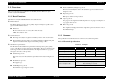
EPSON Stylus CX3100/3200 Revision A 5.1.2 Dedicated Tools 5.2 Adjustment by Adjustment Program Table 5-2 shows the dedicated tools for executing the adjustment items listed above. Table 5-2. Dedicated Tools This machinery is adjusted by using the dedicated adjustment program. Adjusted compensation values are written into EEPROM on the Main Board. 1 Adjustment Program Mechanism setting Dedicated program 2 EFlash3.
EPSON Stylus CX3100/3200 Revision A 5.2.2 Adjustment Program Start 1. From the menu, select the item for which the adjustment is to be made. (Refer to Table 5-3) When the Adjustment Program is started, the screen as shown in Figure 5-1 is displayed. Select the Model Name. Table 5-3. Adjustment Item Menu Menu Adjustment Adjustment Item for which setting can be made Destination Setting (EEPROM Initialization) (p.61) Head ID Input (p.62) Bi-D Adjustment (p.63) USB ID Input (p.
EPSON Stylus CX3100/3200 Revision A 5.2.3 Destination Setting (EEPROM Initialization) The Adjustment Program has the following buttons. Quit Click the [Quit] button, and a menu screen to select [Quit] or [Next] will be displayed. Clicking the [Quit] button on that menu screen will complete the adjustment and close the program. Clicking the [Next] button will return the display to the screen for selecting a Model Name and Destination.
EPSON Stylus CX3100/3200 Revision A 5.2.4 Head ID Input With this item, you can write the Head ID in EEPROM and check the current set value. This adjustment compensates for the unevenness of ink eject volume and ensure satisfactory print quality. Unless the correct ID is input, unevenness in print density can occur. This adjustment is required on any of the following occasions.
EPSON Stylus CX3100/3200 Revision A 5.2.5 Bi-D Adjustment C A U T IO N For Head ID, use the 11-digit character string described in the Print Head. Example: T17R4TUTTTG This adjustment corrects the deviation of printing timing for bidirectional printing which can occur due to variation of assembly precision/component parts of the Printer Mechanism. In this adjustment, print the Bi-D Pattern and adjust so that the pattern can be correctly printed. And the current setting value can be checked.
EPSON Stylus CX3100/3200 Revision A 1. Click the item for which the adjustment is to be made and click the [OK] button. When you select “Printing the Bi-D adjustment pattern”, you can print the pattern. When “Checking present Bi-D parameter” is selected, the set value is indicated at the lower center of the screen. When you select “Input Bi-Directional adjustment value”, you can input the adjusted values. 2.
EPSON Stylus CX3100/3200 Revision A 5.2.6 USB ID Input 2. Stylus CX3100/3200 is equipped with the USB Interface as standard. As the USB Port Driver controls the device through the USB ID on Windows98 or iMac, a proper USB ID is assigned to this product. Since the USB ID is stored in EEPROM on the Main Board, the USB ID needs to be input again when the Main Board has been replaced with a new one.
EPSON Stylus CX3100/3200 Revision A 5.2.7 Top Margin Adjustment 4. Select the desired one of the "+", "0" and "-" buttons and press the "OK" button for setting. Select "+" to enlarge the margin or "-" to lessen it. Three levels are available for selection. 5. Print the pattern again and check the top margin. 6. Determine the setting value so that the top margin as close to the specified value as possible. By this adjustment, set the value of top margin. 1.
EPSON Stylus CX3100/3200 Revision A 5.2.8 First Dot Position Adjustment This adjustment corrects the left margin (Print start position) for post card printing and A4 printing. The value indicated at the center of the adjustment window is the current value recorded in EEPROM. 1. Press the [Print] button to print the adjustment pattern. Figure 5-13. First Dot Position Adjustment Mode Figure 5-12. First Dot Position 2.
EPSON Stylus CX3100/3200 Revision A 5.2.9 Head Cleaning 5.2.10 Ink Charge You can execute more intensive cleaning than Head Cleaning, which is carried out by selecting it in the menu on the Operation Panel. This function releases the Head Nozzle from clogging which can cause dot missing. When the Head or Printer Mechanism has been replaced, ink is not available in the ink route just after its installation, thus ink needs to be filled.
EPSON Stylus CX3100/3200 Revision A 5.2.11 Protection Counter This counter controls total ink eject volume and displays error status if the volume exceeds the set value, displaying the waste ink overflow indication (printer error indication and Error LED blinking.). By selecting this item, you can check or clear the protection counter. This operation is necessary after the following work. Waste Ink Porous Pad replacement Click the item to be executed and click the [OK] button.
EPSON Stylus CX3100/3200 Revision A 5.2.12 EEPROM Data Backup 5.2.13 Check Pattern Printing This function is to back up data and write it on the new board when the Main Board has been replaced with a new one. For example, with the conventional models, whenever the Main Board is replaced, the ink counter is automatically reset and can not be handed down to the new board. With this function, however, the original data can be used with the new board, thus the adjustment process can be shortened.
EPSON Stylus CX3100/3200 Revision A 5.2.14 EEPROM Data With this function, even in error status, you can check the data in EEPROM or write data in it by directly designating addresses in EEPROM. (But if the CPU of the Main Logic Circuit, I/F Receiver, RAM or EEPROM is broken down, this function can not be used.) Check “EEPROM data” in the additional function menu, and the following menu will be indicated.
EPSON Stylus CX3100/3200 Revision A 5.3 Firmware Uploading C A U T IO N The firmware for Stylus CX3100/3200 is stored in flash ROM on the C497MAIN Board. Therefore, firmware can be reinstalled by uploading it from the personal computer without disassembling the machine. This section describes the procedure for uploading firmware. C A U T IO N If the error display as shown below has appeared, take the following actions: Change the underlined model name indicated below in “C497_Bessho.
EPSON Stylus CX3100/3200 Revision A 3. C A U T IO N 1. Firmware is available in the Motorola format (with the extension as *.MOT). If the firmware file has a different extension, rewrite it to MOT. Upon successful completion of firmware transfer, the window as shown below will be displayed on the EFlash3 screen. The power to Stylus CX3100/3200 will automatically be turned off. Once power is turned on next time, Stylus CX3100/ 3200 will operate on the new firmware.
CHAPTER 6 MAINTENANCE
EPSON Stylus CX3100/3200 Revision A 6.1 Overview 6.1.2 Maintenance of the Scanner This section describes maintenance work to maintain the functions and performance of this product. 6.1.2.1 Lubrication Points of the Scanner (TBD) 6.1.1 Cleaning When any part of the CR Unit of the scanner has been replaced or the sound of carriage moving is loud, lubrication is necessary. Figure 6-1 and Figure 6-2 below indicate the designated grease and lubrication points. Clean if dirt is visible.
EPSON Stylus CX3100/3200 Revision A 6.1.3 Maintenance of the Printer 6.1.3.3 Lubrication Points of the Printer If print irregularity (dot missing, white line, etc.) has occurred or the printer indicates “Maintenance Error”, take the following actions to clear the error. The kinds and volume of the oils and grease for lubrication of the Printer are determined based on factory evaluation.
EPSON Stylus CX3100/3200 Revision A Table 6-4. Designated Lubrication Points (continued) Table 6-4. Designated Lubrication Points Lubrication Points / Amount of Application Figure Lubrication Points Figure 6-2 Figure 6-3 • 4 positions on the periphery of the CR guide shaft Grease to be applied • G-58 Amount of Application • 100 mg in total (25 mg at each position) • Do not apply to any part of the carriage unit other than specified. • Use an injector to apply grease.
EPSON Stylus CX3100/3200 Revision A G-58 30 mm G-58 Figure 6-2. Lubrication Points of the Printer 1 Figure 6-4. Lubrication Points of the Printer 3 20 mm G-58 Figure 6-3. Lubrication Points of the Printer 2 G-58 Figure 6-5.
EPSON Stylus CX3100/3200 Revision A G-46 G-58 G-46 Figure 6-8. Lubrication Points of the Printer 7 Figure 6-6. Lubrication Points of the Printer 5 G-58 Figure 6-7.
CHAPTER 7 APPENDIX
EPSON Stylus CX3100/3200 Revision A 7.1 Connectors 7.1.1 Connector Assignments Figure below shows the connector assignments on the circuit boards of Stylus CX3100/ 3200. Figure 7-1.
EPSON Stylus CX3100/3200 Revision A 7.
EPSON Stylus CX3100/3200 Revision A 7.3 Electric Circuit Diagrams This section shows electric circuit diagrams of Stylus CX3100/3200.
EPSON Stylus CX3100/3200 Revision A 7.
EPSON Stylus CX3100/3200 Revision A 7.