
Service manual
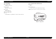

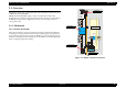
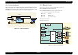
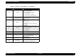

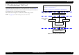
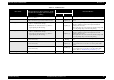
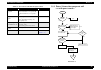
Table Of Contents
- EPSON Stylus CX3100/3200
- PRODUCT DESCRIPTION
- Operating Principles
- Troubleshooting
- Disassembly and Assembly
- Adjustment
- 5.1 Overview
- 5.2 Adjustment by Adjustment Program
- 5.2.1 Adjustment Program Installation
- 5.2.2 Adjustment Program Start
- 5.2.3 Destination Setting (EEPROM Initialization)
- 5.2.4 Head ID Input
- 5.2.5 Bi-D Adjustment
- 5.2.6 USB ID Input
- 5.2.7 Top Margin Adjustment
- 5.2.8 First Dot Position Adjustment
- 5.2.9 Head Cleaning
- 5.2.10 Ink Charge
- 5.2.11 Protection Counter
- 5.2.12 EEPROM Data Backup
- 5.2.13 Check Pattern Printing
- 5.2.14 EEPROM Data
- 5.3 Firmware Uploading
- Maintenance
- Appendix
EPSON Stylus CX3100/3200 Revision A
Operating Principles Overview 15
2.1.1.2 Scanner Mechanism
The scanner consists of the Scanner Carriage Unit comprising the CCD for capturing
images and the light source for illuminating the document, the Scanner Motor and
Timing Belt for moving the scanner carriage unit along the document surface, and the
Scan HP Detector for detecting the position of the scanner carriage unit.
Figure 2-2. Scanner Mechanism
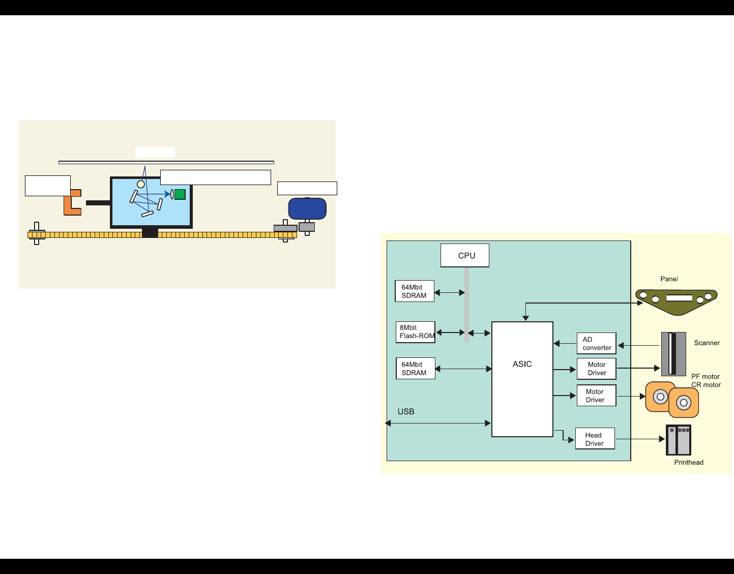
2.1.2 Electric Circuit
The electric circuit boards of Stylus CX3100/3200 are as follows:
C497MAIN Board (main circuit board)
C497PSB/C497PSE Board (power supply circuit board)
This circuit board supplies the following voltages:
+3.3V: For logic
+42V: Driving power
+12V: Power to the scanner
Scanner circuit board
Panel circuit board
Figure 2-3. Electric Circuit Block
Scanner Carriage Unit
Scanner Motor
Scanner HP
Detector
Document