
Service manual
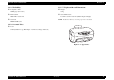

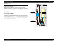
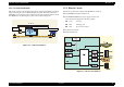
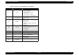

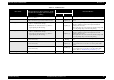
Table Of Contents
- EPSON Stylus CX3100/3200
- PRODUCT DESCRIPTION
- Operating Principles
- Troubleshooting
- Disassembly and Assembly
- Adjustment
- 5.1 Overview
- 5.2 Adjustment by Adjustment Program
- 5.2.1 Adjustment Program Installation
- 5.2.2 Adjustment Program Start
- 5.2.3 Destination Setting (EEPROM Initialization)
- 5.2.4 Head ID Input
- 5.2.5 Bi-D Adjustment
- 5.2.6 USB ID Input
- 5.2.7 Top Margin Adjustment
- 5.2.8 First Dot Position Adjustment
- 5.2.9 Head Cleaning
- 5.2.10 Ink Charge
- 5.2.11 Protection Counter
- 5.2.12 EEPROM Data Backup
- 5.2.13 Check Pattern Printing
- 5.2.14 EEPROM Data
- 5.3 Firmware Uploading
- Maintenance
- Appendix
EPSON Stylus CX3100/3200 Revision A
Operating Principles Overview 16
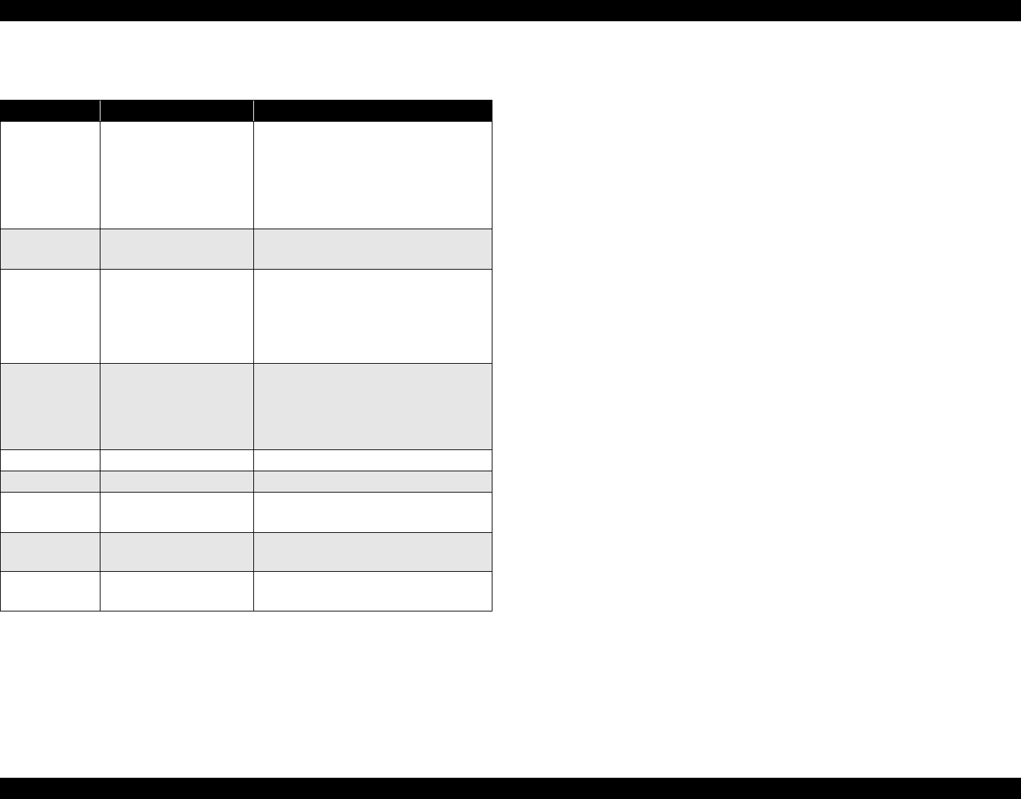
Table 2-1. Functions of Major Elements - C497MAIN
Location Name Description
IC1 C90A20**
CPU
• Built-in RAM 10kB,
Built-in Flash ROM 256KB
• 144-pin, LQFP,
Driving frequency: 48MHz
• Control, image processing C90A20
IC5
MBM29LV800BC-PFTN
or the equivalent
64Mbit Flash ROM
• Stores firmware
IC2 E05C08**
ASIC
• Motor control
• Head control
• Panel sensor input and output control
•USB I/F
IC4 RTC9822
•EEPROM
• Storage of default setting and backup of
various parameters
• Reset function
•Timer function
IC7 A6615 CR Motor driver
IC11 LB11847 Scanner motor driver
IC6 E09A29LA
Head drive control IC
• Supplies COMMON+42 V
IC8 K4S641632D
16Mbit SDRAM
• System memory
IC9 K4S641632D
16Mbit SDRAM
• Work area for copy functions