
Service manual


Table Of Contents
- EPSON Stylus CX3100/3200
- PRODUCT DESCRIPTION
- Operating Principles
- Troubleshooting
- Disassembly and Assembly
- Adjustment
- 5.1 Overview
- 5.2 Adjustment by Adjustment Program
- 5.2.1 Adjustment Program Installation
- 5.2.2 Adjustment Program Start
- 5.2.3 Destination Setting (EEPROM Initialization)
- 5.2.4 Head ID Input
- 5.2.5 Bi-D Adjustment
- 5.2.6 USB ID Input
- 5.2.7 Top Margin Adjustment
- 5.2.8 First Dot Position Adjustment
- 5.2.9 Head Cleaning
- 5.2.10 Ink Charge
- 5.2.11 Protection Counter
- 5.2.12 EEPROM Data Backup
- 5.2.13 Check Pattern Printing
- 5.2.14 EEPROM Data
- 5.3 Firmware Uploading
- Maintenance
- Appendix
EPSON Stylus CX3100/3200 Revision A
Disassembly and Assembly Disassembly Process 38
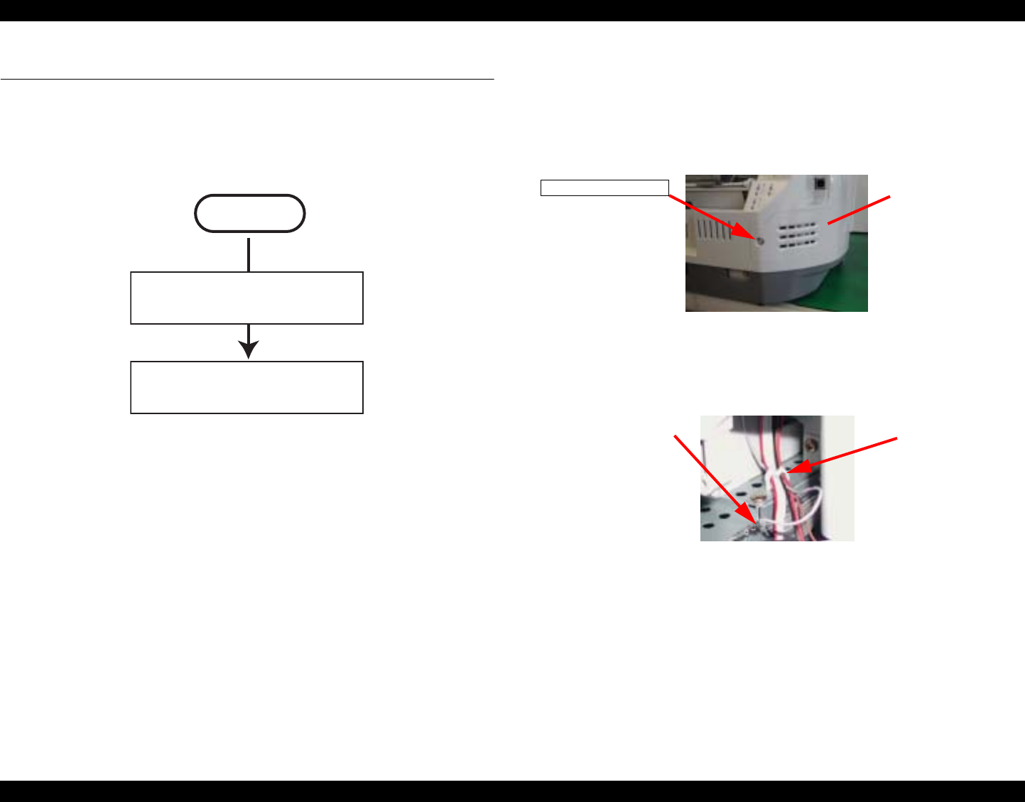
4.2 Disassembly Process
The flowchart below shows Disassembly Process
Figure 4-1. Flowchart (1)
4.2.1 Scanner Unit Removal
1. Remove the one screw (CBP-Tite 3x10 F/Zn) securing the FFC Cover to the Middle
Housing.
NOTE: Screw tightening torque: 0.5 -0.7 Nm
Figure 4-2. Screw securing the Connector Cover
2. Remove the FFC Cover.
3. Disconnect the Harness Grounding Plate from the terminals on the Power Supply Unit.
Figure 4-3. Harness Grounding Plate
4. Release the harness of the Scanner from the Mini Clamp on the Power Supply Unit.
START
“Scanner Unit Removal”
on page 38
“Disassembly of Printer”
on page 44
CBP-Tite 3x10
FFC Cover
Harness Grounding Plate
Mini Clamp