
Service manual


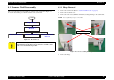
Table Of Contents
- EPSON Stylus CX3100/3200
- PRODUCT DESCRIPTION
- Operating Principles
- Troubleshooting
- Disassembly and Assembly
- Adjustment
- 5.1 Overview
- 5.2 Adjustment by Adjustment Program
- 5.2.1 Adjustment Program Installation
- 5.2.2 Adjustment Program Start
- 5.2.3 Destination Setting (EEPROM Initialization)
- 5.2.4 Head ID Input
- 5.2.5 Bi-D Adjustment
- 5.2.6 USB ID Input
- 5.2.7 Top Margin Adjustment
- 5.2.8 First Dot Position Adjustment
- 5.2.9 Head Cleaning
- 5.2.10 Ink Charge
- 5.2.11 Protection Counter
- 5.2.12 EEPROM Data Backup
- 5.2.13 Check Pattern Printing
- 5.2.14 EEPROM Data
- 5.3 Firmware Uploading
- Maintenance
- Appendix
EPSON Stylus CX3100/3200 Revision A
Disassembly and Assembly Scanner Unit Disassembly 40
4.3 Scanner Unit Disassembly
This section describes the disassembly procedure for the scanner unit. Figure 4-7
shows the disassembly procedure flowchart for the scanner unit.
Figure 4-7. Flowchart (2)
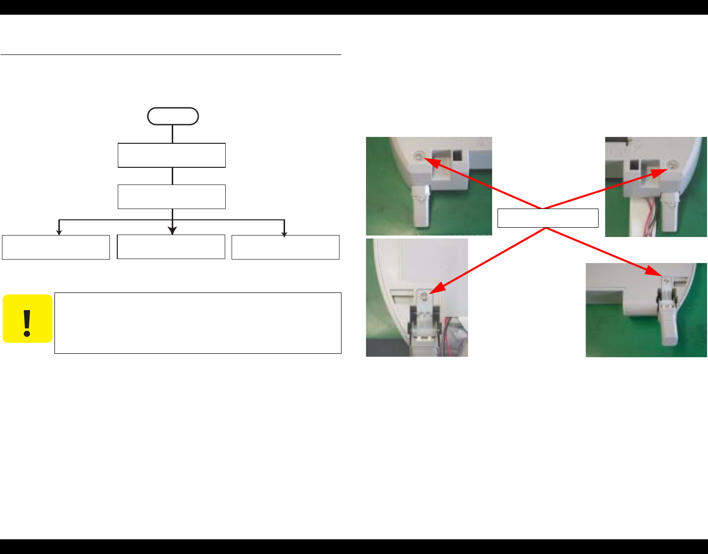
4.3.1 Hinge Removal
1. Remove the scanner unit. (Refer to “Scanner Unit Removal” on page 38)
2. Remove the document cover.
3. Remove the four screws (CBP-Tite 3x10 F/Zn) securing the hinge to the scanner unit.
NOTE: Screw tightening torque: 0.5-0.7 Nm
Figure 4-8. Screws securing the Hinge
4. Remove the hinge.
C A U T I O N
Perform disassembly and assembly of the scanner unit in an
environment free from dust. You are advised to work in a clean
room or on a clean bench, if possible.
START
Hinge Removal
Upper Housing
Removal
Motor Unit Removal CCD Module Removal Panel Circuit Board
Removal
CBP-Tite 3x10 F/Zn