
Service manual
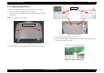
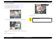


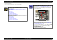
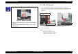


Table Of Contents
- EPSON Stylus CX3100/3200
- PRODUCT DESCRIPTION
- Operating Principles
- Troubleshooting
- Disassembly and Assembly
- Adjustment
- 5.1 Overview
- 5.2 Adjustment by Adjustment Program
- 5.2.1 Adjustment Program Installation
- 5.2.2 Adjustment Program Start
- 5.2.3 Destination Setting (EEPROM Initialization)
- 5.2.4 Head ID Input
- 5.2.5 Bi-D Adjustment
- 5.2.6 USB ID Input
- 5.2.7 Top Margin Adjustment
- 5.2.8 First Dot Position Adjustment
- 5.2.9 Head Cleaning
- 5.2.10 Ink Charge
- 5.2.11 Protection Counter
- 5.2.12 EEPROM Data Backup
- 5.2.13 Check Pattern Printing
- 5.2.14 EEPROM Data
- 5.3 Firmware Uploading
- Maintenance
- Appendix
EPSON Stylus CX3100/3200 Revision A
Disassembly and Assembly Scanner Unit Disassembly 41
4.3.2 Upper Housing Removal
1. Remove the scanner unit. (Refer to “Scanner Unit Removal” on page 38)
2. Remove the hinge. (See “Hinge Removal” on page 40)
3. Remove the two screws (CCP-Tite 3x8 F/Zb) securing the upper housing to the
scanner unit.
NOTE: Screw tightening torque: TBD
Figure 4-9. Screws securing the Upper Housing
4. Disengage the two hooks fastening the upper housing and lower housing.
Figure 4-10. Hook Position
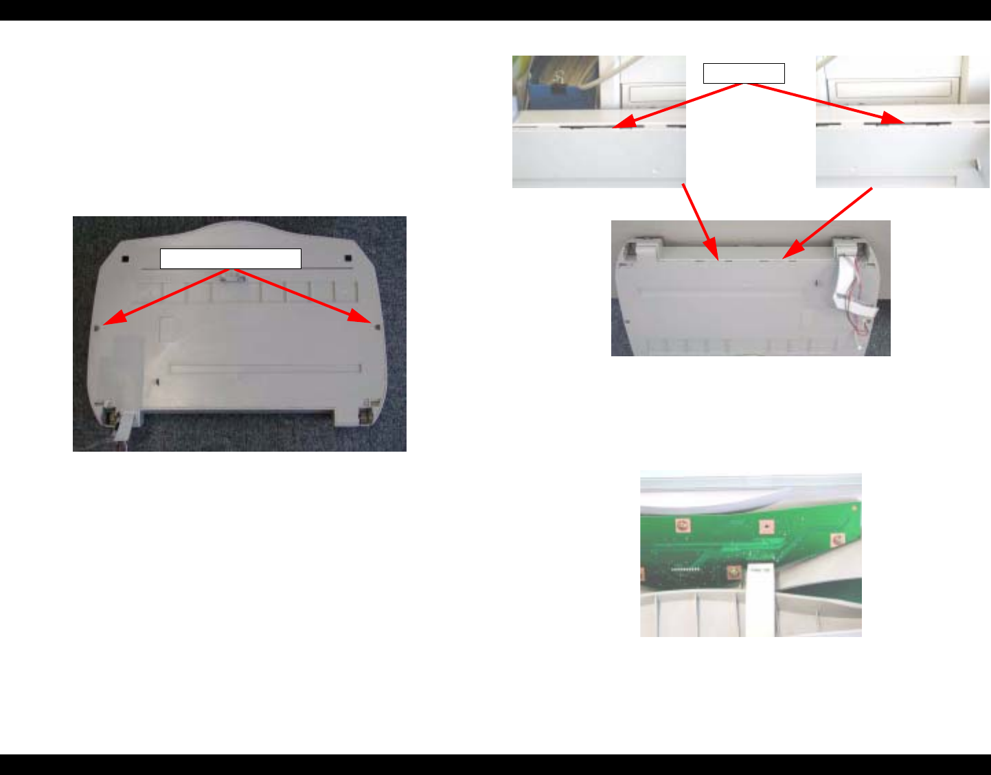
5. Open the upper housing by lifting it from the rear.
6. Insert your hand through the opening and disconnect the harness for the panel from the
connector on the panel circuit board.
Figure 4-11. Harness Disconnection
CCP-Tite 3x8 F/Zn
Hook