
Service manual
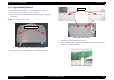
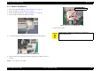
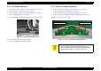


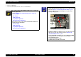
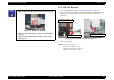


Table Of Contents
- EPSON Stylus CX3100/3200
- PRODUCT DESCRIPTION
- Operating Principles
- Troubleshooting
- Disassembly and Assembly
- Adjustment
- 5.1 Overview
- 5.2 Adjustment by Adjustment Program
- 5.2.1 Adjustment Program Installation
- 5.2.2 Adjustment Program Start
- 5.2.3 Destination Setting (EEPROM Initialization)
- 5.2.4 Head ID Input
- 5.2.5 Bi-D Adjustment
- 5.2.6 USB ID Input
- 5.2.7 Top Margin Adjustment
- 5.2.8 First Dot Position Adjustment
- 5.2.9 Head Cleaning
- 5.2.10 Ink Charge
- 5.2.11 Protection Counter
- 5.2.12 EEPROM Data Backup
- 5.2.13 Check Pattern Printing
- 5.2.14 EEPROM Data
- 5.3 Firmware Uploading
- Maintenance
- Appendix

EPSON Stylus CX3100/3200 Revision A
Disassembly and Assembly Disassembly of Printer 48
4.4.3 ASF Unit Removal
1. Remove the Middle Housing. (See “Middle Housing Removal” on page 44.)
2. Remove the three screws, namely, one C.B.P-Tite 3x6 F/Zn, one C.B.S-Tite(P4) 3x6
F/Zn and one C.B.P-Tite 3x8 F/Zn, which secure the ASF Unit to the printer
mechanism.
Figure 4-24. Removing the ASF Unit Securing Screws
3. Remove the ASF Unit.
NOTE: Screw tightening torque
C.B.P-Tite 3x8 F/Zn:0.5-0.7 Nm
C.B.S-Tite(P4) 3x6 F/Zn: 0.7-0.9 Nm
C.B.P-Tite 3x8 F/Zn: 0.7-0.9 Nm
C H E C K
P O I N T
Installing the FFC Holder
Make certain that the Head FFC has been installed properly.
Figure 4-23. Installing the Head FFC
Make sure that the Head FFC is connected to the Print Head
properly.
Make sure that the FFC Holder is installed on the Carriage
Unit properly.
C.B.P-Tite 3x8 F/Zn
C.B.S-Tite 3x6 F/Zn
C.B.S-Tite 3x6 F/Zn