
Service manual
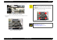
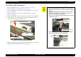
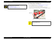


Table Of Contents
- EPSON Stylus CX3100/3200
- PRODUCT DESCRIPTION
- Operating Principles
- Troubleshooting
- Disassembly and Assembly
- Adjustment
- 5.1 Overview
- 5.2 Adjustment by Adjustment Program
- 5.2.1 Adjustment Program Installation
- 5.2.2 Adjustment Program Start
- 5.2.3 Destination Setting (EEPROM Initialization)
- 5.2.4 Head ID Input
- 5.2.5 Bi-D Adjustment
- 5.2.6 USB ID Input
- 5.2.7 Top Margin Adjustment
- 5.2.8 First Dot Position Adjustment
- 5.2.9 Head Cleaning
- 5.2.10 Ink Charge
- 5.2.11 Protection Counter
- 5.2.12 EEPROM Data Backup
- 5.2.13 Check Pattern Printing
- 5.2.14 EEPROM Data
- 5.3 Firmware Uploading
- Maintenance
- Appendix
EPSON Stylus CX3100/3200 Revision A
Disassembly and Assembly Disassembly of Printer 53
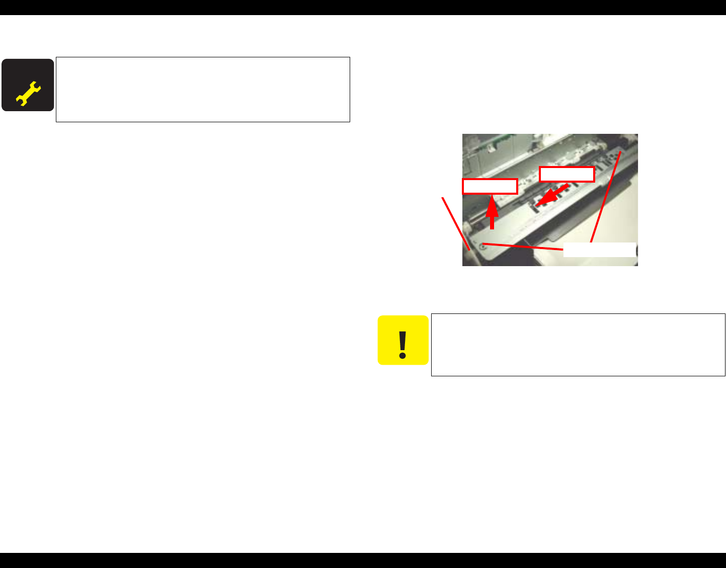
4.4.7 Front Frame Unit Removal
1. Remove the Middle Housing. (See “Middle Housing Removal” on page 44.)
2. Move the Carriage Unit to the home position by hand.
3. Remove the two screws (C.B.S. 3x6 F/Zn) securing the Front Frame Unit.
4. Lift the left end of the Front Frame Unit and move it to the left carefully for removal.
Figure 4-35. Removing the Front Frame Unit
A D J U S T M E N T
R E Q U I R E D
Once the Holder Shaft Unit has been removed or replaced, make
adjustments in the order specified below:
1. Bi-D Adjustment (See p.63)
2. First Dot Position Adjustment (See p.67)
C A U T I O N
When removing and installing the Front Frame Unit, take care not
to damage the Spur Gear 60.
Spur Gear 60
C.B.S. 3x6
Step 1
Step 2