
Service manual


Table Of Contents
- EPSON Stylus PHOTO RX500/510
- Product Description
- Operating Principles
- Troubleshooting
- Disassembly and Assembly
- Adjustment
- Maintenance
- Appendix
EPSON Stylus PHOTO RX500/510 Revision C
Appendix Connectors 86
7.1 Connectors
7.1.1 Connector Assignments
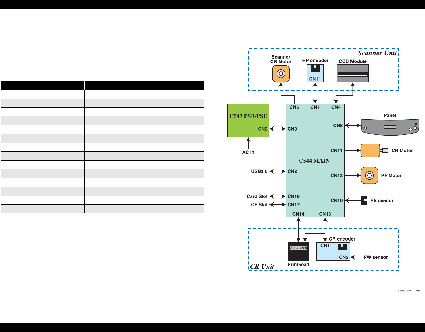
Figure below shows the connector assignments on the circuit boards of Stylus PHOTO
RX500/510.
Figure 7-1. Connector Assignments of Circuit Boards
Table 7-1.
CN No. Color Pins Connected to
CN2 - 4
USB2.0
CN3 White 14
Power Unit
CN4 (FFC) 25
CCD Module
CN5 White 5
TPU Inlet Holder
CN6 Red 4
Scanner Motor
CN7 White 3
HP sensor circuit board
CN8 (FFC) 30
Panel circuit board
CN10 White 3
DETECTOR circuit board
CN11 Black 4
CR Motor
CN12 White 4
PF Motor
CN13 (FFC) 19
Print Head
CN14 (FFC) 25
Print Head
CN16 -
Card Slot
CN17 - 50
Card Slot (CF)