EPSON COLOR INKJET PRINTER Stylus Pro XL SERVICE MANUAL EPSON 4004677
Chapter 1 Product Description Table of Contents 1.1 FEATURES 1-1 1.2 SPECIFICATIONS 1.2.1 Printing Specifications . . . . . . . . . . . . . . . . . . . . . . . . . . . . . . . . . . . . . . . . 1.2.2 Paper Handling Specifications . . . . . . . . . . . . . . . . . . . . . . . . . . . . . . . . . . 1.2.3 Paper Specifications. . . . . . . . . . . . . . . . . . . . . . . . . . . . . . . . . . . . . . . . . . 1.2.4 Ink Cartridge Specifications . . . . . . . . . . . . . . . . . . . . . . . . . . . . . . . . .
List of Figures Figure 1-1. Exterior View of the Stylus Pro XL Figure 1-2. Nozzle Configuration Figure 1-3. Printable Area for Cut Sheet Figure 1-4. Printable Area for Envelope Figure 1-5. Adjustment Lever Setting Figure 1-6. Temperature/Humidity Range Figure 1-7. Data Transmission Timing Figure 1-8. Control Panel Appearance Figure 1-9. C162 MAIN Board Component Layout Figure 1-10. C137 PSB/PSE Board Component Layout Figure 1-11. Printer Mechanism (M-4A60) List of Tables Table 1-1.
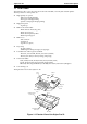
Stylus Pro XL Product Description 1.1 FEATURES The Stylus Pro XL is a 64 + 48-nozzle (monochrome and CMY) color ink jet dot matrix printer.
Product Description Stylus Pro XL Table 1-1. Interface Cards Interface Card Model Number Serial interface card C823051/C823061 32KB serial interface card C823071/C823081 32KB parallel interface card C82310✽ 32KB IEEE-488 interface card C82313✽ LocalTalk® interface card C82312✽ Twinax interface card C82315✽ Coax interface card C82314✽ ✽ The asterisk represents the last digit, which varies by country. 1-2 Rev.
Stylus Pro XL Product Description 1.2 SPECIFICATIONS This section provides statistics and other detailed information for the printer. 1.2.
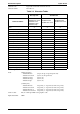
Product Description Stylus Pro XL Character sets: Legal and 14 international character sets. Character tables: See Table 1-3. Table 1-3. Character Tables Bit map font Character Tables EPSON Roman EPSON Sans Serif EPSON Courier EPSON Prestige EPSON Script EPSON Roman EPSON Sans Serif EPSON Roman EPSON Sans Serif H ❍ ❍ m ❍ ❍ ❍ ❍ m m ❍ ❍ ❍ ❍ m m ❍ ❍ ❍ ❍ ❍ m m m m ❍ ❍ ❍ ❍ ❍ m m m ❍ m m ❍ ❍ m m × × ❍ ❍ m m × × ❍ ❍ ❍ ❍ m m m m × × × × Italic PC437 (U.S.
Stylus Pro XL Product Description 1.2.2 Paper Handling Specifications Feeding method: Notes: Friction feed paper is fed from the built-in auto sheet feeder (ASF). The following operations are not allowed. 1. Reverse feeding within 3 mm (0.12 in.) from the top edge of the paper or 16 mm (0.63 in.) from the bottom edge of the paper. 2. Reverse feeding beyond 7.9 mm (0.3 in.). Line spacing: 1/6 inch feed, 1/8 inch feed, or programmable with a 1/360 inch minimum increment.
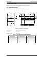
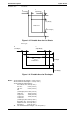
Product Description Printable area: Stylus Pro XL Cut sheets B (Left Margin) C (Right Margin) A (Top Margin) Printable Area D (Bottom Margin) Figure 1-3. Printable Area for Cut Sheets Envelopes B (Left Margin) C (Right Margin) Printable Area A (Top Margin) D (Bottom Margin) Figure 1-4. Printable Area for Envelopes Notes: 1-6 A: The minimum top margin = 3 mm (0.12 in.) B: The minimum left margin = 3 mm (0.12 in.) C: The minimum right margin is: A3+/US B+ size: 3mm (0.12 in.) A3 size: 3 mm (0.
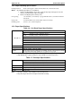
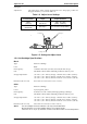
Stylus Pro XL Product Description Setting the adjust lever: The adjust lever on the carriage unit must be set to the proper position for the paper thickness, as shown in Table 1-6. Table 1-6. Adjust Lever Settings Lever Position Paper Paper Thickness LEFT (Vertical) Cut Sheets 0.08 ∼ 0.11 mm (0.003 ∼ 0.004 in.) RIGHT (Horizontal) Envelopes Less than 0.5 mm (0.020 in.) Cut Sheets Envelopes Carriage Unit Figure 1-5. Setting the Adjust Lever 1.2.
Product Description Stylus Pro XL 1.2.5 Electrical Specifications Table 1-7. Rated Electrical Ranges Specification 120 V Version 220 - 240 V Version 120 VAC 220 - 240 VAC 103.5 ∼ 132 V 198 ∼ 264 V Rated frequency range 50 ∼ 60 Hz 50 ∼ 60 Hz Input frequency range 49.5 ∼ 60.5 Hz 49.5 ∼ 60.5 Hz 0.6 A 0.4 A Rated voltage Input voltage range Rated current Approx. 20 W Approx.
Stylus Pro XL Product Description 1.2.7 Reliability Total print volume: 75,000 pages (A4, letter) Printhead life: 1,000 million dots/nozzle 1.2.8 Safety Approvals Safety standards: 120 V version: 220-240 V version: Radio frequency interference (RFI): 120 V version: 220-240 V version: UL1950 with D3, CSA22.2 #950 with D3 EN 60950 (TÜV, SEMKO, DEMKO, NEMKO, SETI) FCC Part 15 Subpart B Class B Vfg.243 (VDE0878 part 3, part 30) EN55022 (CISPR PUB. 22) class B 1.2.
Product Description Stylus Pro XL 1.3 INTERFACE SPECIFICATIONS The Stylus Pro XL is standard-equipped with an 8-bit parallel and serial interface. 1.3.1 Parallel Interface Specifications Data format: 8-bit parallel Synchronization: By STROBE pulse synchronization Handshaking: By BUSY and ACKNLG signals Signal level: TTL compatible level Adaptable connector: 36-pin 57-30360 (Amphenol) or equivalent Data transmission timing: See Figure 1-7.
Stylus Pro XL Product Description Table 1-9 shows the connector pin assignments and signal functions of the 8-bit parallel interface. Table 1-9. Signal and Connector Pin Assignments for Parallel Interface Pin No. 1 2-9 * Signal Name STROBE DATA 1-8 I/O* Description I The STROBE pulse is used to read data from the host computer. The pulse width must be 0.5 µs or more. Normally, it is HIGH, and data is latched with the rising edge of this signal. I DATA 1-8 are parallel data bits.
Product Description Stylus Pro XL 1.3.2 Serial Interface Specifications Data format: RS-422 serial Synchronization: Asynchronous Handshaking: By DTR signal and X-ON/X-OFF protocol Table 1-10. DTR and X-ON/X-OFF Protocol State Buffer Space Busy Less than 512 bytes Off X-OFF Ready More than 1,024 bytes On X-ON DTR Word length Start bit: Data bit: Parity bit: Stop bit: 1 bit 8 bit none 1 bit Bit rate: 57.6K bps /230.
Stylus Pro XL Product Description 1.4 OPERATIONS This section describes the basic operations of the printer. 1.4.1 Control Panel The control panel for this printer has 1 lock-type, 5 non-lock-type push buttons, and 14 LED indicators for easy operation of the various printer functions. Operate Alt Fon t Econ omy/ Condensed Load/Eject Pau se Figure 1-8. Control Panel Appearance Buttons Operate Turns the printer on or off. Alt Modifies the function of other buttons.
Product Description Stylus Pro XL Indicators Operate On when the printer is on. Blinks during power on and off sequence. Data On when print data is in the input buffer. Data and Pause lights blink if an error occurs. Paper Out On when the printer is out of paper. Blinks when a paper jam occurs. No Ink Cartridge On when ink cartridge is out. Economy On when economy printing mode is selected. Condensed On when condensed printing mode is selected. Font These LEDs indicate the selected font.
Stylus Pro XL Product Description 1.4.3 Default Settings The printer can save some printer setting parameters that define its functions at initialization. You can change these parameters by using the printer’s default setting mode. 1.4.3.1 Default Setting Items You can use the default setting mode to change settings listed in the table below. Activate default-setting mode by holding down Economy/Condensed while turning on the printer. Table 1-13.
Product Description Stylus Pro XL 1.4.3.2 Changing the Default Settings To change the printer’s default settings: 1. Hold down the Economy/Condensed button and turn on the printer. The printer prints a sheet that shows the firmware version and describes how to select the language used to print messages. 2. Press the Font button until the appropriate font LED is selected. The following table shows which language corresponds to which font LED. Table 1-16.
Stylus Pro XL Product Description Table 1-18. Character Table Selection Data LED Paper Out LED Off Off Off On Off Off Blinks Off Off Italic U.K. Off On Off Italic Denmark 1 On On Off Version Settings Common Italic U.S.A.
Product Description Stylus Pro XL 1.4.4 Error Conditions The printer can detect various errors and indicate them with LEDs. Table 1-19. Error Indications Paper Out LED No Ink Cartridge LED Off On Off Off Off Off No ink cartridge Off Off On Off Off Off Paper jam Off Blinks Off Off Off Off Maintenance request Blinks Blinks Blinks Blinks Blinks Blinks Carriage error Blinks Off Off Off Off Blinks Error Data LED Paper out Economy Condensed LED LED Pause LED 1.4.
Stylus Pro XL Product Description 1.5 MAIN COMPONENTS The main components of the Stylus Pro XL are: ❏ ❏ ❏ ❏ ❏ Printer mechanism (M-4A60) Main control board (C162 MAIN Board) Power supply unit (C137 PSB/PSE Board) Control panel board (C137 PNL Board) Housing 1.5.
Product Description Stylus Pro XL 1.5.2 Power Supply Board (C137 PSB/PSE Board) The power supply board (C137 PSB/PSE Board) consists of an RCC switching regulator circuit. This board is equipped with a power switch connected to the secondary circuit. Thus, if the printer is turned off, it can continue to operate in order to eject the paper and perform the head capping operation.
Stylus Pro XL Product Description 1.5.4 Printer Mechanism (M-4A60) The M-4A60 printer mechanism is equipped with a 64-nozzle black printhead and 48-nozzle color (CMY) printhead on the carriage unit. Resolution of 720 dpi is possible with special (non-absorbent) paper. The ink system has both a black pump unit and a color pump unit. Waste ink from each printhead is made to flow into the individual caps. Power for the pump system and paper feed system is supplied from the paper feed motor. Figure 1-11.
Chapter 2 Operating Principles Table of Contents 2.1 OVERVIEW 2-1 2.2 OPERATING PRINCIPLES OF THE PRINTER MECHANISM 2-1 2.2.1 Printer Mechanism . . . . . . . . . . . . . . . . . . . . . . . . . . . . . . . . . . . . . . . . . . . 2-2 2.2.2 Carriage Drive Mechanism. . . . . . . . . . . . . . . . . . . . . . . . . . . . . . . . . . . . . 2-5 2.2.2.1 Platen Gap Adjust Lever . . . . . . . . . . . . . . . . . . . . . . . . . . . . . . . . 2-6 2.2.3 Paper Feed Mechanism . . . . . . . . . . . . . . . . . . . .
List of Figures Figure 2-1. Printer Mechanism Block . . . . . . . . . . . . . . . . . . . . . . . . . . . . . . . . . 2-1 Figure 2-2. Structure of Printhead . . . . . . . . . . . . . . . . . . . . . . . . . . . . . . . . . . . 2-2 Figure 2-3. Principles of the Printing Operation . . . . . . . . . . . . . . . . . . . . . . . . . 2-3 Figure 2-4. Carriage Drive Mechanism . . . . . . . . . . . . . . . . . . . . . . . . . . . . . . . 2-5 Figure 2-5. Platen Gap Lever Operation . . . . . . . . . . . . . . . . . .
Stylus Pro XL Operating Principles 2.1 OVERVIEW This section describes the operating principles of the printer mechanism and the electrical circuits of the Stylus Pro XL. 2.2 OPERATING PRINCIPLES OF THE PRINTER MECHANISM The Stylus Pro XL printer mechanism is composed of the printhead unit, paper feed mechanism, carriage drive mechanism, pump mechanism, and various sensors. The figure below shows a functional block diagram of the printer mechanism.
Operating Principles Stylus Pro XL 2.2.1 Printer Mechanism The printer mechanism of this printer uses a drop-on-demand ink jet system similar to the system used on all other EPSON ink jet printers. However, the printhead in this system is completely redesigned to make it more compact and ensure a high level of reliability. The figure below shows the structure of the printhead and ink supply system.
Stylus Pro XL Operating Principles Principles of the Printing Operation The printhead operates in one of two modes to eject ink from each nozzle: ❏ Normal state No electrical charge is applied to the MLP (Multi-Layer Piezoelectric) element attached to the back of the cavity, and pressure inside the cavity is kept at a constant level.
Operating Principles Stylus Pro XL Micro Dot Printing mode The Stylus Pro XL printer has a special printing mode, called “Micro Dot Printing mode”. This printing mode can be selected by a command from the host computer. Using the Micro Dot printing mode can improve the quality of output. In Micro Dot Printing mode, the ink dot size became to be smaller than the normal dot size. 2-4 REV.
Stylus Pro XL Operating Principles 2.2.2 Carriage Drive Mechanism The timing belt attached to the base of the carriage unit is driven by the carriage motor, causing the carriage unit to move along the carriage guide shaft left to right, or vice versa. The carriage drive motor on this printer is a 4-phase, 200-pole, hybrid-type stepping motor mechanism, allowing the printer to stop the carriage or change the carriage movement at any position.
Operating Principles Stylus Pro XL 2.2.2.1 Platen Gap Adjust Lever The platen gap adjust lever, which is attached to the carriage unit, needs to be set to an appropriate position for the paper thickness. To change the platen gap, put the printer in the PAUSE state; then press the Font button, while holding down the Alt button. The carriage unit moves the platen gap position automatically. Table 2-3.
Stylus Pro XL Operating Principles Table 2-5.
Operating Principles Stylus Pro XL 2.2.4 Ink System This printer’s ink system is composed of the following mechanisms: ❏ ❏ ❏ ❏ ❏ Ink cartridge Pump mechanism Cap mechanism Waste ink drain tank Wiping mechanism The figure below shows a diagram of the ink system. Color Head Black Head Cleaning Blade (for Color / Black Head) Friction Clutch Disengage Unit Air Valve Pump 1 Pump Unit PF Motor Platen Roller Pump 2 Ink Absorber Waste Ink Drain Tank Figure 2-7. Ink System Block Diagram 2-8 REV.
Stylus Pro XL Operating Principles 2.2.5 Pump Mechanism The paper feed motor drives the pump mechanism when the transmission gear is moved to the position where the paper feed motor engages the pump mechanism gear trains, when the carriage unit is at the ink system home position. The figure below shows a block diagram of the pump mechanism. Pump system operation depends on the rotational direction of the paper feed drive motor, as shown in Table 2-6.
Operating Principles Stylus Pro XL Drive: Paper Feed Mechanism Carriage Figure 2-10. Paper Feed Mechanism Block Diagram Switch Lever: Reset Carriage D/E Reset Lever D/E Lever Figure 2-11. Switch Lever Reset 2-10 REV.
Stylus Pro XL Operating Principles Table 2-6. Pump Mechanism Operation PF Motor Rotational Direction Operation Clockwise (CW) forward rotation ❏Color absorption ❏Color micro absorption ❏Color false absorption ❏Wiper reset ❏Carriage lock reset Counterclockwise (CCW) backward rotation ❏Monochrome absorption ❏Monochrome micro absorption ❏Monochrome false absorption ❏Wiper set ❏Carriage lock set The pump draws ink from the printhead nozzles and drains it to the waste ink drain tank.
Operating Principles Stylus Pro XL 2.2.6 Cap Mechanism The cap mechanism prevents the printhead nozzles from drying and keeps bubbles from forming inside the nozzle while the printer is not in use. The printer performs this operation automatically when print data is not received or when the printer power is turned off during printing or ink system operations. (The secondary circuit for the power switch allows this operation to be performed.
Stylus Pro XL Operating Principles 2.3 OPERATING PRINCIPLES OF THE ELECTRICAL CIRCUITS The Stylus Pro XL contains the following circuit board units: ❏ ❏ ❏ C162 MAIN Board (main control circuit board) C137 PSB/PSE Board (power supply circuit board) C137 PNL (control panel board) In addition to the circuit boards above, part of the printhead drive circuit is built on a separate circuit board installed in the carriage unit; the printhead is attached directly to this board.
Operating Principles Stylus Pro XL The figure below shows a block diagram of the power supply circuit (C137 PSB/PSE). The power switch is equipped with a secondary circuit that allows the CPU to remain active for a while after the printer is turned off. This allows the printhead to return to the capping position after power is off. The CPU mounted on the C137 MAIN Board always monitors the PSC (power on/off) signal.
Stylus Pro XL Operating Principles 2.3.2 Operating Principles of the Main Control Circuit The main control circuit of this printer is the C162 MAIN Board. This circuit is controlled by the 16-bit CPU H8/3003 (IC1), running at 14.7456 MHz. This CPU has a unique architecture capable of handling data on the data bus at either an 8-bit or 16-bit bus width. Because of this, a 16-bit or 8-bit data bus width-type ROM is used on this board, increasing the internal processing speed.
Operating Principles Stylus Pro XL 2.3.2.1 Reset Circuits The C162 MAIN Board contains 2 reset circuits: the +5 V monitor reset circuit and the +35 V monitor reset circuit. The +5 V monitor reset circuit monitors the voltage level of the +5 V line, using reset IC PST592D (IC12), and outputs a reset signal to the E05A96 gate array (IC2) when the voltage level drops below +4.2 V.
Stylus Pro XL Operating Principles 2.3.2.3 Carriage Motor Drive Circuit The carriage motor drive IC SLA7041MS (IC15) outputs a constant current to drive the carriage motor for the printer mechanism. Gate array E05A96EA (IC2) decides the motor phase and speed and then sends a signal to the carriage motor driver IC (SLA7041MS) using the 4-bit serial transmission line. The first bit indicates the direction of the motor rotation.
Operating Principles Stylus Pro XL The following figure shows the contents of the four-bit serial data and how this data transacts with the SLA7041MS driver. The step time of the reference voltage is determined by the interval time of the STROBE pulse.
Stylus Pro XL Operating Principles 2.3.2.4 Paper Feed Motor Drive Circuit The paper feed motor for this printer drives the following mechanisms: ❏ ❏ ❏ Paper feed mechanism Paper pickup mechanism Pump mechanism Driver IC SLA7041MS (IC14) drives the paper feed motor by a constant current. Its principle of operation is same as for the carriage motor drive circuit. But the driving method is different for paper feed and the pump. Table 2-9.
Operating Principles Stylus Pro XL 2.3.2.5 Printhead Drive Circuit The printhead drive circuit for this printer is composed of the following two parts: ❏ ❏ Common drive circuit (trapezoidal drive pulse generation) Head drive circuit (nozzle control built on the printhead) SED5620D, the 64-bit thermal head driver in the head drive circuit on the carriage, is used as a nozzle selector to drive the printhead nozzles selectively.
Stylus Pro XL Operating Principles Micro Dot Printing Mode The Stylus Pro XL printer has a special printing mode, called “Micro Dot Printing Mode.” This printing mode can be selected by command from computer. Using Micro Dot Printing Mode can improve the quality of output. In Micro Dot Printing Mode, the ink dot size becomes smaller than the normal dot size.
Operating Principles Stylus Pro XL 2.3.2.6 DMA Controller Data from the host computer is received automatically by the STB signal via the external Centronics interface. The data is input to the input buffer on the DRAM (IC5). At this time, E05A96 detects the rising edge of the external STB signal and outputs the STBDMA (strobe DMA request) signal to the CPU.
Stylus Pro XL Operating Principles 2.3.2.7 DRAM Refresh Controller The H8 CPU is equipped with a refresh controller in the internal controller. This CPU can contact the 16-bit-long IC5 DRAM, which is a 2 CAS type. The following table lists the junction method between the H8 CPU and the 2 CAS DRAM. Table 2-10. Junction Method (CPU — 2 CAS DRAM) CPU 2 CAS DRAM HWR UCAS LWR LCAS CS3 RAS RD WR The method of the DRAM refresh is used only for the CAS before RAS cycle method.
Operating Principles Stylus Pro XL 2.4 INK SYSTEM MANAGEMENT This section explains how the ink system is controlled to protect the printhead and ink supply system and to ensure high-quality output.
Stylus Pro XL Operating Principles 2.4.1 Ink Operations Various ink operations can be performed selectively by the printer. 1 Power On Operation This operation is performed when power is turned on. 2 Cleaning Selection Mode This operation cleans each nozzle to ensure that the nozzle fires and that no dots are skipped during printing. Cleaning selection is performed by pressing the cleaning switch (Alt + Load/Eject or Economy/Condensed) while the printer is in PAUSE status.
Operating Principles Stylus Pro XL 14 Disengage Off Operation This operation resets the switch lever to the position where it transmits the PF motor drive to the pump mechanism. It also moves the carriage to the flushing position, where the lever is reset to the specified position. 15 Micro Absorbing Operation When the cartridge is removed, it is possible for a small amount of air to form small air bubbles that can block the ink from the nozzle.
Stylus Pro XL Operating Principles 2.4.2 Timer and Counter EEPROM LE93C46 (IC12) on the main board stores certain counter and timer values used for controlling ink system operation. 2.4.2.1 Protect Counter Protect counter A and Ink Amount Counter R values are stored in the EEPROM on the main board, and while the printer is on, this data is saved in the RAM on the main board. ❏ Protect Counter A 1. Power On (Micro): This counter is used to manage the total amount of drained ink.
Chapter 3 Disassembly and Assembly Table of Contents 3.1 OVERVIEW 3-1 3.1.1 Precautions for Disassembling the Printer . . . . . . . . . . . . . . . . . . . . . . . . . 3-1 3.2 DISASSEMBLY AND ASSEMBLY 3-2 3.2.1 Upper Case Removal . . . . . . . . . . . . . . . . . . . . . . . . . . . . . . . . . . . . . . . . . 3-3 3.2.2 Power Supply Unit (C137 PSB/PSE Board) Removal . . . . . . . . . . . . . . . . 3-4 3.2.3 Main Controller (C162 MAIN Board) Removal . . . . . . . . . . . . . . . . . . . . . . 3-5 3.2.
List of Figures Figure 3-1. Disassembly Flowchart . . . . . . . . . . . . . . . . . . . . . . . . . . . . . . . . . . 3-2 Figure 3-2. C137 PNL Control Panel Removal . . . . . . . . . . . . . . . . . . . . . . . . . 3-3 Figure 3-3. Upper Case Removal. . . . . . . . . . . . . . . . . . . . . . . . . . . . . . . . . . . . 3-3 Figure 3-4. Power Supply Unit Removal . . . . . . . . . . . . . . . . . . . . . . . . . . . . . . 3-4 Figure 3-5. Main Controller Removal . . . . . . . . . . . . . . . . . . . . . . . . .
Stylus Pro XL Disassembly and Assmbly 3.1 OVERVIEW This section describes procedures for disassembling the main components of this printer. Unless otherwise specified, disassembled units or components can be reassembled by reversing the disassembly procedure. Therefore, no assembly procedures are included. Precautions for any disassembly or assembly procedure are described under the heading “Disassembly/Assembly Points.
Disassembly and Assembly Stylus Pro XL 3.2 DISASSEMBLY AND ASSEMBLY WARNING Follow the precautions in Section 3.1.1 when disassembling the printer. This section consists of the subheads shown in the diagram below. See the exploded view of the printer in the Appendix, if necessary. START Printhead Unit Remo va l Upper Case Remo va l 3.2.1 3.2.5.1 Page 3-8 Page 3-3 Carriage Unit Remo va l Power Supply Unit Remo va l 3.2.2 3.2.5.2 Page 3-12 Page 3-4 Pump Unit Remova l Main Controller Removal 3.2.
Stylus Pro XL Disassembly and Assmbly 3.2.1 Upper Case Removal 1. Remove the printer cover (center of top) by releasing the 2 tabs holding it to the upper case. 2. Remove the front cover (front of top) by releasing the 2 tabs holding it to the lower case. 3. Remove the paper guide by releasing the 2 tabs holding it to the printer mechanism. 4. Move the carriage to the middle of the printer while pressing the hook that fixes the carriage unit to the home position. 5. Remove the control panel.
Disassembly and Assembly Stylus Pro XL 3.2.2 Power Supply Unit (C137 PSB/PSE Board) Removal 1. Remove the upper case (see Section 3.2.1). 2. Disconnect the cables from connectors CN1 on the C137 PSB /PSE Board and CN5 on the C162 MAIN Board. 3. Remove the 2 screws, 1 CBN (M3×8) and 1 CBB (M3×12), securing the shield plate to the lower case via the C137 PSB/PSE Board. 4.
Stylus Pro XL Disassembly and Assmbly 3.2.3 Main Controller (C162 MAIN Board) Removal 1. Remove the upper case (see Section 3.2.1). 2. Remove the grounding plate from the shield plate. 3. Remove the 4 CBB (M3×12) screws securing the shield plate to the lower case. 4. Remove the 2 CBB (M3×12) screws securing the Type-B interface cover to the lower case. 5. Disconnect the cables from connectors CN5, CN6, CN7, CN8, CN9, CN10, CN11, CN12, and CN13 of the C162 MAIN Board.
Disassembly and Assembly Stylus Pro XL ASSEMBLY POINT ❏ When you replace the main board, initialize EEPROM contents as follows: 1. Reassemble the printer. 2. Turn the printer on while holding down the Alt, Font , Load/Eject , and Pause buttons on the control panel. ❏ It is possible to misconnect the cables. When reconnecting the cables from connectors CN6, CN7 and connectors CN11, CN12 of the C162 MAIN board, see the following instructions. 1.
Stylus Pro XL Disassembly and Assmbly 3.2.4 Printer Mechanism (M-4A10) Removal 1. Remove the upper case (see Section 3.2.1). 2. Remove the power supply unit (see Section 3.2.2). 3. Remove the main controller (see Section 3.2.3). 4. Remove the 4 CBN (M4×13) screws and take out the printer mechanism. DISASSEMBLY/ASSEMBLY POINT Wipe off any ink around the end of the ink drain tube when you remove the printer mechanism.
Disassembly and Assembly Stylus Pro XL 3.2.5 Printer Mechanism Disassembly The procedures described in this section explain how to remove the components within the printer mechanism. 3.2.5.1 Printhead Unit Removal 1. Remove the printer mechanism (see Section 3.2.4). 2. Move the carriage to the middle of the printer while pressing the hook that fixes the carriage unit to the home position. 3. Pull the ink cartridge clamp toward you and remove the ink cartridge.
Stylus Pro XL 6. Disassembly and Assmbly Remove the CBB (M3×11) screw (under the CR cap cover) and plain washer securing the monochrome and color printheads to the carriage base. Rubber Cap CBB (M3x11) Head Fixing Sczew CBB (M3x11) Figure 3-8. Ink Cartridge Holder Removal 7 Pull the black or color head toward you, and disconnect the head FFC cable on the head driver board (nozzle selector). Then remove the black or color head. Color Head Black Head Figure 3-9. Printhead Removal REV.
Disassembly and Assembly Stylus Pro XL CAUTION ❏ Take proper measures to protect the printhead unit from static electricity, because the driver IC is directly attached to the printhead unit. ❏ Never touch the printhead’s metallic nozzle cover surface. Handle it only by holding the edges of the printhead. ❏ When you replace the printhead or the printer mechanism, you must replace the block resistor at location RM4 (for Micro Mode - Color (R-No.)), RM5 (for Normal Mode Color (M-No.
Stylus Pro XL Disassembly and Assmbly REQUIRED ADJUSTMENT ❏ When removing or changing the black head, the following adjustments are needed. 1. Black head angle adjustment (see Section 4.1.4). 2. Black - Color head vertical adjustment (see Section 4.1.5). 3. Head gap adjustment (see Section 4.1.3). 4. Bidirectional alignment adjustment (see Section 4.1.2). ❏ When removing or changing the color head, the following adjustments are needed. 1. Color head angle adjustment (see Section 4.1.6). 2.
Disassembly and Assembly Stylus Pro XL 3.2.5.2 Carriage Unit Removal 1. Remove the printer mechanism (see Section 3.2.4). 2. Move the carriage to the left side of the printer while pressing the hook that fixes the carriage to the home position. 3. Remove the 2 CBN (O) (M3× 6) screws securing the eject frame to both side frames. CBS(O) (M3x6) CBS(O) (M30x11) Eject Frame Figure 3-11. Front Frame Removal 4. Remove the cartridge holder with ink cartridge from the carriage unit (see Section 3.2.5.1).
Disassembly and Assembly Stylus Pro Service Manual 3.2.5.3 Pump Unit Removal 1. Remove the printer mechanism. (See Section 3.2.4.) 2. Remove the carriage unit. (See Section 3.2.5.2.) 3. Remove the CBS (M3×6) screw securing the pump unit to the bottom frame. 4. Push the pump unit outward while releasing the tab at the bottom side of the pump unit, and then lift up the pump unit. CBS (M3x6) (2 ) (1 ) Bottom Frame (2) Pump Unit Figure 3-14. Pump Unit Removal 3-12 Rev.
Disassembly and Assembly Stylus Pro XL 3.2.5.4 Cleaner Head Replacement 1. Remove the printer mechanism (see Section 3.2.4). 2. Use tweezers to unhook the cleaner head from the hook on the cleaning lever. CAUTION Keeping the cleaner head clean is extremely important to keep the ink injection system working properly in the printhead, and it directly affects printing quality. Therefore, handle the cleaner head very carefully, and observe the following precautions.
Stylus Pro XL Disassembly and Assmbly 3.2.5.5 CR Motor Removal 1. Remove the printer mechanism (see Section 3.2.4). 2. Release the timing belt (see section 3.2.5.2). 3. Remove the 3 screws securing the CR motor to the upper frame, and then remove the CR motor. Screws CR Motor Figure 3-15. CR Motor Removal 3.2.5.6 PF Motor Removal 1. Remove the printer mechanism (see Section 3.2.4). 2. Remove the 2 CBN (M3×6) screws and then remove the PF motor. CBS (M3x6) PF Motor Figure 3-16.
Stylus Pro Service Manual Disassembly and Assembly 3.2.5.7 Carriage Home Position Sensor Removal 1. Remove the printer mechanism. (See Section 3.2.4.) 2. Disconnect the sensor cable from the carriage home position sensor. 3. Unhook the 3 notches securing the carriage home position sensor to the upper frame. Then remove the carriage home position sensor. Se nsor Cable Ca rriage Home Position Sensor Figure 3-18. Carriage Home Position Sensor Removal 3.2.5.8 PE Sensor Removal 1.
Stylus Pro XL Disassembly and Assmbly 3.2.5.9 Paper Feed Roller Assembly Removal 1. Remove the printer mechanism (see Section 3.2.4). 2. Remove the carriage unit (see Section 3.2.5.2). 3. Remove the pump unit (see Section 3.2.5.3). 4. Remove the tension spring holding the tension roller assembly to the sub frame. 5. Remove the tension wire on the left side frame holding the tension roller assembly to the left side frame. 6.
Disassembly and Assembly Stylus Pro XL 3.2.5.10 Upper Frame Removal 1. Remove the printer mechanism (see Section 3.2.4). 2. Remove the carriage unit (see Section 3.2.5.2). 3. Remove the E-ring securing the knob shaft to the sub frame; then remove the knob with the knob shaft from the right side frame. 4. Remove the 5 CBN (M3×5) screws securing the upper frame to both side frames or the sub frame. Then remove the upper frame with 4 PF support rollers. 5.
Chapter 4 Adjustments Table of Contents 4.1 OVERVIEW 4-1 4.1.1 Destination Data Writing Operation . . . . . . . . . . . . . . . . . . . . . . . . . . . . . . 4-2 4.1.2 Bi-D (Bidirectional Printing) Alignment Adjustment . . . . . . . . . . . . . . . . . . 4-3 4.1.3 Head Gap Adjustment (Black and Color Head) . . . . . . . . . . . . . . . . . . . . . 4-4 4.1.4 Black Head Angle Adjustment . . . . . . . . . . . . . . . . . . . . . . . . . . . . . . . . . . 4-5 4.1.5 Black-Color Head Vertical Adjustment . . . .
Stylus Pro XL Adjustments 4.1 OVERVIEW This section describes adjustments required when the printer is disassembled and assembled after repair. Since this printer has both a black and color head, it needs new adjustments not required for previous printers. Refer to the following table to perform the appropriate adjustments. WARNING ❏ Always perform the adjustments in the order indicated. ❏ After performing steps 1-5, perform a cleaning operation for the black and color printheads.
Adjustments Stylus Pro XL 4.1.1 Destination Data Writing Operation The setup value that specifies the printer destination is stored in the EEPROM on the C162 MAIN board. Therefore, this setup value must be written into the EEPROM when the MAIN board or EEPROM chip is replaced. CAUTION Before writing the destination data writing, set the interface to parallel. 1. Connect the PC to the target printer using a parallel interface cable and turn the printer on. 2.
Stylus Pro XL Adjustments 4.1.2 Bi-D (Bidirectional Printing) Alignment Adjustment The bidirectional alignment is required when the printer mechanism, main board, or printhead (board) is replaced. Performing this adjustment determines a compensation value to rectify any deviation in the print position.
Adjustments Stylus Pro XL 4.1.3 Head Gap Adjustment (Black and Color Head) The head gap adjustment is required when the printer mechanism, main board, or printhead (board) is replaced or diassembled. This adjustment calibrates the head drive timing between the black and color head. If this adjustment is not made, the vertical alignment will not be completed. 1. Connect the PC to the target printer, and turn the printer on. 2. Execute BASIC on the PC and run the program “VERxxx.BAS.” 1.
Stylus Pro XL Adjustments 4.1.4 Black Head Angle Adjustment The black head angle adjustment is required when the black head is replaced or disassembled. If this adjustment is not correct, a white banding problem may occur, or the color head timing may not match the black head timing. The following figure illustrates the black head angle adjustment. The black head angle is adjusted with linear and angular spacers.
Adjustments Stylus Pro XL 1. Connect the PC to the target printer, and turn the printer on. 2. Execute BASIC on the PC and run the program “VERxxx.BAS.” 1. Destination Setting 2. Head Angle Confirmation Pattern Printing (Black Head Spacer Selection) 3. Head Vertical Position Confirmation 4. Head Gap Adjustment 5. Bi-D Adjustment 6. Internal Timer Reset 7. END 3. When the main menu appears, choose “Head Angle Confirmation Pattern Printing” by typing 2 and ENTER.
Stylus Pro XL Adjustments 7. Turn the printer power off now. 8. Manually move the carriage to the center while pressing the carriage lock lever, and remove the two ink cartridges. 9. Remove the rubber cap covering the head screw at the side of color ink cartridge. Then loosen (but do not remove) 3 screws. (Refer to Figure 4-6.) Carriage Unit Black Head 1: Push Head Base Angular Spacer Platen Gap Adjust Lever 2: Replace Linear Spacer (Angular Spacer Replacement Position) Figure 4-6.
Adjustments Stylus Pro XL 11. After replacing the angular spacer, reassemble the ink cartridge holder and reinstall the ink cartridges. Use the BASIC program to verify the angle of the black head. Confirm the angle by performing the steps 1 to 6 again, and if the angle is wrong, perform the adjustment again until the head angle is correct. WARNING ❏ The angular spacer comes in five thicknesses. Continue performing this adjustment, by changing the black head angle is correct.
Stylus Pro XL Adjustments 4.1.5 Black - Color Head Vertical Adjustment This adjustment calibrates the vertical position between the black head and the color head. Align the top nozzles (both nozzle #1 on the black head and nozzle #1 on the color head). You can make this adjustment by using only the linear spacers for the black head. This adjustment is required when the black head or the color head is replaced or disassembled. The following figure illustrates this adjustment.
Adjustments 4. Stylus Pro XL In Figure 4-10, the vertical position is correct when both the magenta line and the black line are aligned (as shown in position OK (0)). If the vertical position is correct, turn off the printer. If the black and magenta lines are not aligned, perform the vertical adjustment as described in steps 5-10. WARNING ❏ The number shown in the sample indicates the thickness level compared to the current linear spacer. (See * .
Stylus Pro XL 8. Adjustments Change the linear spacers (2 spacers for the monochrome head only) with new ones, referring the figure below. (Replace linear spacers using tweezers to push the head base toward the rear.) Carriage Unit Black Head 1: Push He ad B ase Angu lar Spacer Platen Gap Adjust Lever Linear Spacer x 2 2: Replace (Linear Spacer Rep lacement Position) Figure 4-11. Linear Spacer Replacement Method 9.
4.1.6 Color Head Angle Adjustment The color head angle adjustment is required when the color head is replaced or disassembled. If this adjustment is not correct, a white banding problem may occur, or the black head timing may not match the color head timing. The following figure illustrates the color head angle adjustment. The color head angle is adjusted by the angular spacer. The angular spacer is attached only to the left side of the head base. 1.
Stylus Pro XL Adjustments Angular spacers for the color head come in five thicknesses, each having its own shape. The following figure shows the relationship between the shape and thickness. Since the color head is not equipped with a linear spacer, the angle adjustment is decided only by the angular spacer (specifically designed for the color head), which is placed under the left side of the head base. Angular Spacer (for Color Head) Spacer Name Thickness angular spacer YMC 0.
Adjustments Stylus Pro XL 7. Ru bber Cap Screw 1 Screw 2 Screw 3 Figure 4-16. Removing the Rubber Cap Remove the rubber cap covering the head screw at one side of color ink cartridge. Then loosen (but do not remove) 3 screws. (Refer to the figure below.) 8. Replace the angular spacer on the left side with a new one, referring the figure below. (Replace the angular spacer using tweezers to push the head base toward the rear.) 4-14 Rev.
Stylus Pro XL 9. Adjustments Rerun the BASIC program and choose “Head Angle Confirmation Pattern” again by typing 2 and ENTER. Then verify that the confirmation sample is correct. Carriage Unit Color Head 1: Push Head Base Platen Gap Adjust Lever Angular Spacer (one side only) 2: Replace Figure 4-17. YMC Angular Spacer Replacement 10.
Adjustments Stylus Pro XL 4.1.7 Platen Gap Adjustment This adjustment is required when the carriage unit is replaced or removed from the printer mechanism. Adjust the distance between the printhead nose and the paper surface to 1.1 mm. 1. Attach a thickness gauge (commercially available) to the left side adjustment position on the paper guide plate, as shown in the figure below, so that one side hooks the paper feed pinch roller unit. 2. Move the carriage unit manually onto the thickness gauge.
Stylus Pro XL 6. Adjustments Move the carriage manually to the right adjustment position and repeat steps 3 and 4, referring to Figures 4-18 and 4-19. Carriage Roller Gap 0.04 mm Thickness Gauge Eject Frame Figure 4-19. Confirming the Gap 4.1.8 Internal Timer Reset Operation This operation is required when the M-4A60 printer mechanism is replaced. There are 6 timers in this printer: 1. 2. 3. 4. 5. 6.
Chapter 5 Troubleshooting Table of Contents 5.1 OVERVIEW 5-1 5.2 UNIT LEVEL TROUBLESHOOTING 5.2.1 Printer Does Not Operate at Power on . . . . . . . . . . . . . . . . . . . . . . . . . . 5.2.2 Error is Detected. . . . . . . . . . . . . . . . . . . . . . . . . . . . . . . . . . . . . . . . . . . . 5.2.3 Failure Occurs During Printing . . . . . . . . . . . . . . . . . . . . . . . . . . . . . . . . 5.2.4 Printer Does Not Feed the Paper Correctly . . . . . . . . . . . . . . . . . . . . . . 5.2.
Rev.
Stylus Pro XL Troubleshooting 5.1 OVERVIEW The printer may exhibit different symptoms for the same problem, which makes troubleshooting more difficult. However, this section provides simple and effective ways to facilitate troubleshooting. The following flowchart illustrates the main steps of the troubleshooting process. STAR T UNIT LEVEL TROUBLESHOOTING UNIT REPAIR [C137 PSB/PSE BOARD] UNIT REPAIR [C162 MAIN BOARD] UNIT REPAIR [M -4A60 MECHANISM] ASSEM BLY AND ADJUSTMENT END Figure 5-1.
Troubleshooting Stylus Pro XL Table 5-3. Error Codes LED Error Status Data Paper out Paper No Ink Economy Condensed Pause Out Cartridge On No ink cartridge On Paper jam Carriage error 5-2 On Load paper in the tray, press Load/ Eject, and then the Pause button. On Install the new ink cartridge and press the Pause button. Load paper and press Pause and Load/Eject buttons. Blinks Maintenance Blinks Blinks request Blinks Recovery Blinks Blinks Blinks Blinks Service maintenance request.
Stylus Pro XL Troubleshooting 5.2 UNIT LEVEL TROUBLESHOOTING When a problem occurs, you can identify the defective unit based on the symptoms exhibited. The table below lists the symptoms of certain problems. Once the problem is identified, refer to the flowchart that corresponds to the problem. Table 5-4. Symptom and Problem Symptom Problem Flowchart No. Printer does not operate at power on ❏ LEDs do not light up. ❏ Printer mechanism does not operate. 5.2.
Troubleshooting Stylus Pro XL 5.2.1 Printer does not operate at power on. START Is the AC input voltage correct? NO Use the correct input voltage. YE S Has fuse (F1) on the C137 PSB/PSE blown ? YE S R epl ace the fuse and di s connec t C N 5 on t he C 162 MAIN b oard. NO NO YE S Check the output voltage of the C137 PSB/PSE at CN2. Is the output voltage correct? NO YE S Replace the C137 PSB/PSE boar d R epl ac e the C 1 62 MAIN b oard.
Stylus Pro XL Troubleshooting 5.2.2 Error is detected. START Identify the type of error indicated. (See Table 5-3.) Carriage err or YES Turn the printer off and try to move the carriage manu ally. Does the carriage move smoothly? NO No ink cartriage YES Replace the ink cartridge with a new o ne. YES NO Waste ink drain tank overflow YES NO Check CR motor and drivers. If they are OK, replace the C162 M AIN board.
Troubleshooting Stylus Pro XL 5.2.3 Failure occurs during printing. START Run the self-test . Does the selftest print? NO YES Is print quality bad? Are all cables connected to the C162 MAIN board firmly? NO Perform the color or black head cleaning. Is the problem corrected? YES NO Connect the cables correctly. Adjust the bidirectional print alignment or readjust the head arrangement adjustment . (See Chapter 4.
Stylus Pro XL Troubleshooting 5.2.4 Printer does not feed the paper correctly. START Is paper loaded in the sheet feeder correctly? NO Load the paper correctly. YES Does a paper jam occur? YES NO Verify that the paper path is clear. Also confirm that there are no foreign objects that may interfere with paper movement. Is the problem corrected? Check the PF motor and driver. If OK, replace the C162 MAIN board.
Troubleshooting Stylus Pro XL 5.2.5 Control panel operation is abnormal. START Is the control panel connected properly? NO Connect the control panel correctly. YES Is the problem corrected? YES NO Replace the control panel. Is the problem corrected? YES END NO Replace the C162 MAIN board. END 5-8 Rev.
Stylus Pro XL Troubleshooting 5.3 UNIT REPAIR - C137 PSB/PSE BOARD This section describes problems related to the power supply board (C137 PSB/PSE). The table below provides various symptoms, likely causes, and checkpoints. The checkpoints refer to waveforms, resistances, and other values to check to evaluate the operation of each component. Table 5-5. Repair of the C137 PSB/PSE Symptom Condition Cause Checkpoint Solution Transformer coilsCheck the transformer coils using a Replace T1. are open.
Troubleshooting Stylus Pro XL 5.4 UNIT REPAIR - C162 MAIN BOARD This section describes the problems related to the main controller board (C162 MAIN). The table below provides various symptoms, likely causes, and checkpoints. The checkpoints refer to waveforms, resistance, and other values to be checked to evaluate the operation of each component Table 5-6. Repair of the C162 MAIN Symptom Condition Cause Checkpoint Solution Check the waveform of the +5 V line and that of the RESET signal.
Stylus Pro XL Troubleshooting Table 5-6. Repair of the C162 MAIN (Cont.) Symptom Condition Cause Checkpoint Solution Check the output signal at pins 1, 8 or at 11, 18 of IC15. Carriage does not operate normally. The carriage does not IC15 is defective. operate at all. Replace IC15. Check the output signal at pin 13 or 14 and pin 15 or 16 of IC2. Self-test printing is abnormal. Self-test is not executed. IC2 is defective. Replace IC2. Printhead unit is defective. Replace printhead unit.
Troubleshooting Stylus Pro XL 5.5 UNIT REPAIR - PRINTER MECHANISM (M-4A60) Any problems related to the printer mechanism should be repaired according to the troubleshooting procedures in Table 5-7. Table 5-7. Repair of the Printer Mechanism Symptom The pump mechanism does not operate. Ink is not absorbed or is poorly absorbed. The carriage motor does not rotate. The carriage does not operate normally at power on (after the carriage has been manually centered prior to power on).
Stylus Pro Service Manual Troubleshooting Table 5-8. Repair of the Printer Mechanism (Continued) Symptom Printing is not performed. Condition Paper is not fed normally. Rev.A Checkpoint Solution The head cable is disconnected. Check whether the head cable is disconnected. Reconnect the head cable. The head cable is defective. Replace the head cable to see if operation is normal. Replace the head cable. The printhead is defective.
Troubleshooting Stylus Pro XL Table 5-7. Repair of the Printer Mechanism (Cont.) Symptom Condition Cause Foreign substances are lodged in the paper path. Paper is not fed normally. Paper is not fed. Paper feeding gears are defective. The paper feed motor is defective. Particles of power Paper top of residue from form position coating on glossy slips (comes paper are sticking out too narrow). to the PF roller. Checkpoint Solution Visually check the paper path. Remove any foreign substances.
Chapter 6 Maintenance Table of Contents 6.1 PREVENTIVE MAINTENANCE 6-1 6.2 SERVICE MAINTENANCE 6-2 6.2.1 Printhead Cleaning. . . . . . . . . . . . . . . . . . . . . . . . . . . . . . . . . . . . . . . . . . 6-2 6.2.2 Waste Ink Drain Tank Replacement . . . . . . . . . . . . . . . . . . . . . . . . . . . . 6-2 6.3 LUBRICATION AND ADHESIVE 6-3 LIST OF FIGURES Figure 6-1. Lubrication Points and Adhesive Points (1). . . . . . . . . . . . . . . . . 6-5 Figure 6-2. Lubrication Points and Adhesive Points (2). .
Stylus Pro Service Manual Maintenance 6.1 PREVENTIVE MAINTENANCE Although this printer is designed so that no specific maintenance is required on a regular basis, it is recommended that you clean the printer thoroughly whenever you get a chance to do so. You can clean: ❒ Outer case Use a soft, clean cloth, dampened with mild detergent, if necessary. ❒ Auto sheet feeder If the inside of the auto sheet feeder is dirty (dusty), carefully brush away all dust and dirt using a soft brush.
Maintenance Stylus Pro Service Manual 6.2 SERVICE MAINTENANCE Certain maintenance is required when the printer detects an error or when a decline in print quality is observed. 6.2.1 Printhead Cleaning If print quality deteriorates, clean the printhead using the built-in printhead cleaning function. The printer also has an automatic printhead cleaning cycle to ensure the proper nozzle operation for ink injection as well as to preserve its best condition.
Stylus Pro Service Manual Maintenance 6.3 LUBRICATION AND ADHESIVES The printer must be lubricated properly when it is disassembled for component replacement, or if mechanical noise exceeds a certain level. EPSON recommends only the lubricants listed in the table below for this printer, both of which have been tested extensively and comply with the requirements of this printer mechanism. Figure 6-1 shows the lubrication and adhesive points. Table 6-1. Recommended Lubricants Type Name Quantity Part No.
Maintenance Stylus Pro Service Manual CAUTION ❒ Do not apply too much lubricant, as it may stain the mechanism as well as a cause a mechanism malfunction. 6-4 Rev.
Stylus Pro Service Manual Maintenance 11 6 20 12 5 4 4 7 22 9 30 17 8 17 21 27 2 1 Figure 6-1. Lubrication Points and Adhesive Points (1) Rev.
Maintenance Stylus Pro Service Manual 19 16 1 1 2 2 2 2 11 3 10 (3) 28 14 18 18 14 Lubrication Point Adhesive Point Figure 6-2. Lubrication Points and Adhesive Points (2) 6-6 Rev.
Appendix Table of Contents A.1 CONNECTOR SUMMARY A-1 A.2 CIRCUIT DIAGRAM A-7 A.3 CIRCUIT BOARD COMPONENT LAYOUT A-14 A.4 EXPLODED DIAGRAM A-18 List of Figures Figure A-1. Interconnection of Major Component . . . . . . . . . . . . . . . . . . . . . . . A-1 Figure A-2. C162 MAIN Board Circuit Diagram (1) . . . . . . . . . . . . . . . . . . . . . . A-7 Figure A-3. C162 MAIN Board Circuit Diagram (2) . . . . . . . . . . . . . . . . . . . . . . A-9 Figure A-4. C137 PSB Board CircuitDiagram . . . . . . .
Stylus Pro XL Appendix A.1 CONNECTOR SUMMARY The figure below shows the interconnection between the major components of the Stylus Pro XL. CN1 AC I nput C137 PSB/PSE CN2 CN HP S en sor CN10 CN8 CN9 CN3 CN1 CN11 Printhead Unit C162 MAI N RS -4 22 Serial I/F CN CN13 CN 2 Color ASF Plunger CN2 CN1 Type B Parallel I/F Black CN12 CN5 Parallel I/F CN6 CN7 CR Senso r PF Mot or C137 PNL CR Mot or Printer Mechanism (M-4A60) Figure A-1. Interconnection of Major Components Rev.
Appendix Stylus Pro XL Table A-1.
Stylus Pro XL Appendix Table A-3.
Appendix Stylus Pro XL Table A-6. Connector Pin Assignments — CN6 Pin I/O Name Description 1 O CRA Phase A drive signal 2 O CRA Phase A drive signal 3 O CRB Phase B drive signal 4 O CRB Phase B drive signal 5 O CRCOM Carriage drive power (common voltage) Table A-7.
Stylus Pro XL Appendix Table A-11. Connector Pin Assignments — CN11 Pin I/O Name Description 1 — GND Ground 2 O BCLK Clock signal for black head 3 — GND Ground 4 O BLAT Latch signal for black head 5 — GND Ground 6 O BSI Black head serial data output 7 — GND Ground 8 O BCO Black cartridge out sensor 9 I +5 V Power supply for cartridge out sensor 10 — NC Not connected 11-16 O GP Ground 17-22 O COM Common voltage for printhead drive Table A-12.
Stylus Pro XL Appendix Table A-14. Part No. Reference Table Ref.No. Description PPL Name 100 LOWER HOUSING HOUSING, LOWER 101 FOOT FOOT 102 LOWER SHIELD PLATE SHIELD PLATE, LOWER 103 UPPER SHIELD PLATE SHIELD PLATE, UPPER 104 P/S SHIELD PLATE SHIELD PLATE, P/S 105 GROUNDING PLATE GROUNDING PLATE 106 PAPER SUPPORT COVER B COVER, PAPER SUPPORT; B 107 UPPER HOUSING HOUSING, UPPER 108 REAR PRINTER COVER COVER, PRINTER, REAR 109 PAPER SUPPORT PAPER SUPPORT, ASSY.
Appendix Stylus Pro XL Table A-14. Part No. Reference Table (Continued) Ref.No. Description PPL Name 200 MAIN BOARD (FOR USA, S.E. ASIA) BOARD ASSY., MAIN (FOR USA, S.E. ASIA) 200 MAIN BOARD (FOR EUROPE) BOARD ASSY., MAIN (FOR EUROPE) 300 POWER SUPPLY BOARD (FOR 120 V) BOARD ASSY., POWER SUPPLY (FOR 120V) 300 POWER SUPPLY BOARD (FOR 220 V / 240 V) BOARD ASSY.
Stylus Pro XL Appendix Table A-14. Part No. Reference Table (Continued) Ref.No. Description PPL Name 520 REAR PAPER GUIDE PAPER GUIDE ASSY., REAR 521 PF ROLLER SUPPORT ROLLER, PF, SUPPORT 522 PF HOLDER SUPPORT HOLDER, PF, SUPPORT 523 TORSION SPRING, 5800 TORORSION SPRING, 5800 524 PE HARNESS HARNESS, PE 525 PF STEPPING MOTOR STEPPING MOTOR, PF 526 HP DETECTOR DETECTOR, HP 527 HP HARNESS HARNESS, HP 528 PUMP B PUMP ASSY.
Appendix Stylus Pro XL Table A-14. Part No. Reference Table (Continued) Ref.No. Description PPL Name 561 BK HEAD BASE BASE, HEAD, BK 562 YMC HEAD BASE BASE, HEAD, YMC 563 UPPER HEAD CABLE HOLDER HOLDER, HEAD CABLE, UPPER 564 LOWER HEAD CABLE HOLDER HOLDER, HEAD CABLE, LOWER 565 BK CARTRIDGE LEVER LEVER ASSY., CARTRIDGE, BK 566 YMC CARTRIDGE LEVER LEVER ASSY.
Stylus Pro XL Appendix Table A-14. Part No. Reference Table (Continued) Ref.No. Description PPL Name 603 EXTENTION SPRING, 1.6 g EXTENTION SPRING, 1.
Appendix Stylus Pro XL Table A-14. Part No. Reference Table (Continued) Ref.No. Description PPL Name 650 CBB SCREW (M3×12) C.B.B. SCREW (M3×12) 652 CBS SCREW (M3×8 F/UC) C.B.S. SCREW (M3×8 F/UC) 653 CPB SCREW (3×15 F/ZN) C.P.B. SCREW, 3×15, F/ZN 654 HEAD MOUNTING PRESSURE PLATE PRESSING PLATE, MOUNTING, HEAD 655 PF ROLLER ROLLER, PF 656 SPUR GEAR, 9 mm SPUR GEAR, 9 657 SPUR GEAR, 27 mm SPUR GEAR, 27 659 SPUR GEAR, 12 mm SPUR GEAR, 12 660 PLUNGER PLUNGER ASSY.
EPSON