
User Guide


EPSON Stylus Scan 2500 Revision A
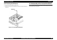
Disassembly & Assembly Disassembling the Printer Mechanism 101
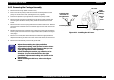
4.6.4.1 Disassembling the ASF Roller Assembly
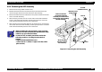
1. Remove the ASF assembly. (Refer to Section 4.6.4.)
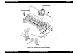
2. Remove the brake lever, releasing one leg of the torsion spring 41.2 from
the hook of the ASF frame.
3. Remove the fixing shaft bushing from the right side of the LD roller shaft
and the release hopper lever.
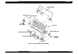
4. Move the left paper feed assembly to the center and remove the cam
fixing bushing (white plastic) attached to the left side of LD roller shaft.
5. Push the LD roller shaft to the left and remove the left shaft fixing bushing
after releasing its hook.
6. Remove the right and left sides of the hopper assembly from the
protrusions on the ASF frame.
7. Lift up the right side of paper feed roller assembly a little, move the LD
roller shaft to the right and remove it from the left side of the ASF frame.
8. Holding the hopper assembly by hand, remove the cam part of hopper
assembly from the right holes of ASF frame.
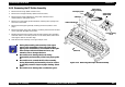
See the next section for details on disassembling the paper-feed roller
assemblies.
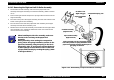
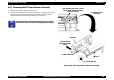
CHECK
PO INT
During disassembly and assembly of the hopper
assembly, do not let the grease on the cam parts
touch other parts. Wipe off any grease smeared on
other parts.
Be careful of the direction of the hopper lever
release when installing it.
Make sure that the right and left fixing bushings are
installed steadily and do not slip off.
During assembly, attach the cam fixing bushing
after installing the LD roller shaft to the ASF frame.
When installing the right and left paper feed roller
assemblies to the LD roller shaft, the black paper
feed roller assembly goes on the right side and the
one in the standard EPSON color goes on the left of
the shaft.