. Epson SureColor F7070 ® User’s Guide ®
Copyrights and Trademarks All rights reserved. No part of this publication may be reproduced, stored in a retrieval system, or transmitted in any form or by any means, electronic, mechanical, photocopying, recording, or otherwise, without the prior written permission of Seiko Epson Corporation. The information contained herein is designed only for use with this Epson printer. Epson is not responsible for any use of this information as applied to other printers.
Contents Chapter 1 Introduction Important Safety Instructions . . . . . . . . . . . . . . . . . . . . . . . . . . . . . . . . . . . . . . . . . . . . . . . . . . 6 When choosing a location for this product . . . . . . . . . . . . . . . . . . . . . . . . . . . . . . . . . . . . 6 When setting up this product . . . . . . . . . . . . . . . . . . . . . . . . . . . . . . . . . . . . . . . . . . . . . . 6 When using this product . . . . . . . . . . . . . . . . . . . . . . . . . . . . . . . . . . . . . . . . . . .
Before Printing . . . . . . . . . . . . . . . . . . . . . . . . . . . . . . . . . . . . . . . . . . . . . . . . . . . . . . . . . . . . Saving Optimal Settings for the Current Media (Print Media Settings) . . . . . . . . . . . . . . . . . Parameters Stored in Media Setting Banks . . . . . . . . . . . . . . . . . . . . . . . . . . . . . . . . . . Saving Settings . . . . . . . . . . . . . . . . . . . . . . . . . . . . . . . . . . . . . . . . . . . . . . . . . . . . . . .
Chapter 5 Problem Solver When a Message is Displayed . . . . . . . . . . . . . . . . . . . . . . . . . . . . . . . . . . . . . . . . . . . . . . When a Maintenance Call/Service Call Occurs . . . . . . . . . . . . . . . . . . . . . . . . . . . . . . . . . . Troubleshooting . . . . . . . . . . . . . . . . . . . . . . . . . . . . . . . . . . . . . . . . . . . . . . . . . . . . . . . . . . You cannot print (because the printer does not work) . . . . . . . . . . . . . . . . . . . . . . . . .
Chapter 1 Introduction Important Safety Instructions Read all of these instructions before using the printer. Also be sure to follow all warnings and instructions marked on the printer. When choosing a location for this product ❏ Place this product on a flat, stable surface that is larger than this product. This product will not operate properly if it is tilted or at an angle. ❏ Avoid places subject to rapid changes in temperature and humidity.
❏ If you use an extension cord with this product, make sure the total ampere rating of the devices plugged into the extension cord does not exceed the cord’s ampere rating. Also, make sure the total ampere rating of all devices plugged into the wall outlet does not exceed the wall outlet’s ampere rating. ❏ If damage occurs to the plug, replace the cord set or consult a qualified electrician. If there are fuses in the plug, make sure you replace them with fuses of the correct size and rating.
❏ If fluid enters your eyes, rinse immediately with water. Failure to observe this precaution could result in bloodshot eyes or mild inflammation. ❏ If swallowed, induce vomiting and consult a physician immediately. The lithium batteries in this product contain Perchlorate Material - special handling may apply. See www.dtsc.ca.gov/hazardouswaste/perchlorate. Warnings, Cautions, Important and Notes w Warning: Warnings must be followed to avoid serious bodily injury.
Printer Parts Front 1 Maintenance cover (left) Open this cover to clean the area around the print head. It is normally closed when the printer is in use. See “Cleaning Around the Print Head” on page 87. 2 Media output (eject) guide Media is output along this guide. 3 Roll core holder Place a used roll core for media take-up on these holders. There are two holders: one on the left and one on the right. See“Media Loading and Take-Up” on page 52.
7 Auto switch Use this switch to select the auto take-up direction. Choose Off to disable auto take-up. 8 Manual switch Use this switch to select the manual take-up direction. The selected option takes effect when the Auto switch is in the Off position. 9 Casters There are two casters on each leg. Once installation is complete, the front casters should be kept locked while the printer is in use. 10 Waste ink bottle (tank) holder Place the waste ink bottle in this holder.
23 Alert lamp This lamp lights or flashes when an error occurs. On/flashing : An error has occurred; the type of error is indicated by how the lamp lights or flashes. Check the message on the control panel’s screen. Off : No error. 24 Control panel See “Control Panel” on page 15. 25 Front cover Open when loading media, cleaning the inside of the printer, or removing jammed media. Normally closed when using the printer.
LAN port 1 RJ-45 connector Connects the LAN cable. Use a shielded twisted pair cable (category 5 or higher). 2 Data lamp (orange) Indicates the network connection status and whether the printer is receiving data. On: Connected Flashing: Receiving data 3 Status lamp (green/red) The color indicates network connection speed.
Interior Dirt on any of the following parts may reduce print quality. Regularly clean or exchange these parts as described in the chapters listed in the reference sections below. 1 Print head The print head prints by moving left and right while emitting ink. Cleaning may be required. See “Cleaning Around the Print Head” on page 87. 2 Media holding plate The media holding plates prevent the media from riding up and keep fuzz on the cut edge of the media from touching the print head.
7 Caps Except during printing, these caps cover the print head nozzles to prevent them from drying out. Cleaning may be required. See “Part Cleaning” on page 86. 8 Wiper The wiper removes ink from the print head nozzles. Cleaning or replacement may be required. See “Part Cleaning” on page 86 See “Replacing the Wiper and Wiper Cleaner” on page 95. Back 1 Drive switch The drive switch is used to feed the media during loading and to rewind the media for replacement.
7 Handle After placing media on the right roll holder, rotate the handle to press the holder and apply pressure to the roll core. Control Panel 1 P button (power button) Turns the power on and off. 2 P light (power light) The printer's operational status is indicated by a lit or flashing light. On : The power is on. Flashing : The printer is receiving data or performing head cleaning or other operations during shut-down. Off : The power is off.
3 M button (media setup button) Press this button to display the Media Setup menu, which contains such items as Media Remaining, Select Media, Customize Settings, and Print Media List. This button is disabled during printing. See “The Media Setup Menu” on page 111. 4 Display Displays the printer's status, menus, error messages, and so on. See “Understanding the Display” on page 17. 5 Menu button Press this button to display menus. See “Using the Control Panel Menu” on page 108.
12 W button (pause/cancel button) The printer enters pause status if this is pressed while printing. To release the pause status, press the W button again, or select Pause Cancel on the screen and then press the Z button. To cancel print jobs being processed, select Job Cancel on the screen and then press the Z button. Pressing this button when menus are displayed closes the menus and returns the printer to ready status.
4 Chip unit status The display changes as shown below when an error is detected in the installed chip unit. Normal Warning or error 1 Status indicators The chip unit status is indicated as follows. : No error. Ready to print. : An error occurred. Check the message on the screen, and clear the error : The chip unit could not be recognized or it is not compatible with the printer. Or, the slider is not locked. Check the on-screen message. : The chip unit requires replacement.
1 Status indicators The status of the waste ink bottle is shown as follows. : No error. The indicator changes to show the amount of space available. : The waste ink bottle is almost full. Ready a new waste ink bottle. : The waste ink bottle is full. Replace with a new waste ink bottle. Features This wide-format color ink jet printer supports roll media up to 1626 mm (64 inches) in width. The main features of this printer are described below.
Superior Ease of Use Easy Media Installation and Take up The roll and roll core holders require no spindles, eliminating the need to attach spindles before installing media. Just bring the media to the printer and install it directly. Never having to juggle long spindles makes installing media a snap even where space is limited.
Notes on Usage and Storage Installation Space Make sure that you secure the following space, clear of any other objects, so that paper ejection and consumable replacement are not obstructed. For the external dimensions of the printer, see “Specifications Table” on page 133. 100 mm (3.9 in.) 500 mm (19.7 in.) 1750 mm (68.9 in.) 1000 mm (39.4 in.) 3620 mm (142.5 in.) mm 00 in.) 10 9.4 (3 2903 mm (114.3 in.) 500 mm (19.7 in.
❏ We recommend performing maintenance on the following components as required. Failure to perform appropriate maintenance will shorten print head life. See “Maintenance Around the Print Head” on page 84. Component to be cleaned Frequency Print head When colors in the printout are faint or missing even after head has been cleaned. Wiper When the printout is smudged or not clear.
Head cleaning will be performed automatically after the printer is turned on. Head cleaning helps maintain print quality. Do not turn the printer off until cleaning is complete. Leaving the printer for too long without turning it on may result in a malfunction. Repair work for such malfunction will be charged. ❏ If you will not be using the printer for more than 2 weeks, maintenance must be performed by a service engineer before and after this period. This maintenance work will be charged.
Notes on Handling Ink Packs and Ink Tanks Note the following points when handling ink packs and ink tanks. ❏ Do not remove the ink tanks Ink tanks are calibrated when installed. Removing them can harm quality and functionality. ❏ Store ink packs at room temperature out of direct sunlight.
❏ Avoid locations that are subject to direct sunlight, excessive heat, or humidity. ❏ When not in use, media should be removed from the printer, rewound, and inserted in its original packaging for storage. Leaving media in the printer for extended periods may cause it to deteriorate. Handling Media After Printing To maintain long lasting, high quality print results, note the following points. ❏ Do not rub or scratch the printed surface. If it is rubbed or scratched, the ink may peel off.
Software Name Summary EPSON LFP Remote Panel 2 EPSON LFP Remote Panel 2 is used to update firmware from a computer and copy the media settings bank created in the printer’s setup menu to a computer. See “Starting EPSON LFP Remote Panel 2” on page 26 and “Exiting EPSON LFP Remote Panel 2” on page 26. Epson Drivers and utilities Install the Epson communications driver (EPSON SC-F7000 Series Comm Driver).
Uninstalling Software Important: ❏ Log in as an administrator. ❏ Enter the administrator password when prompted and then proceed with the remainder of the operation. ❏ Exit any other applications that may be running. This section describes how to uninstall EPSON LFP Remote Panel 2 and the Epson communications driver. 1. Turn off the printer, and unplug the interface cable. 2. Go to the Control Panel and click Uninstall a program from the Programs category. 3.
Chapter 2 Basic Operations Loading and Exchanging Media Loading Media The procedure for loading media varies depending on whether you are using the installed media feeding unit or the optional heavy roll media system. Follow the steps below when using the supplied media feeding unit. When the Heavy Roll Media Feeding Unit is installed, see “Using the Optional Heavy Roll Media Feeding Unit” on page 38. c Caution: ❏ Be careful not to trap your hands or fingers when opening or closing the front cover.
When the Standard Media Feeding Unit Is Installed This section describes how to load media when the standard media feeding unit is installed. c Caution: Because the media is heavy, it should not be carried by one person. When loading or removing the media, use at least two persons. 1. Turn on the printer by pressing the P button. 2. Loosen the roll holder fixing screws and adjust the roll holders so that the gap between the two is wider than the media. Center the roll supports between the roll holders.
3. Place media on the roll support oriented according to how it is rolled (see below) and position it as indicated by the mark on the label. Printable side out Printable side in If the label does not have a loading position, mark it on the label as instructed in the Setup Guide. Note: Be sure the option selected for Roll Type in the Customize Settings menu matches how the media is rolled. Roll Type defaults to Printable Side Out.
4. Raise the roll holder lever on the left side of the printer to lift the media into position, then firmly insert the roll holder. If the roll of media has an outer diameter which is less than 140 mm (5.5 inches), lift it up by your hands, and place it on the roll holder. The roll core will not reach the holder when raised using the roll holder lever. 5. Tighten the roll holder screw to fix the roll holder in place. 6.
If the roll of media has an outer diameter which is less than 140 mm (5.5 inches), lift it up by your hands, and place it on the roll holder as described in step 4. 7. Tighten the roll holder screw to fix the roll holder in place.
8. Rotate the handle until part A in the illustration below is fully inserted. Important: Once part A is hidden, do not turn the handle any further. Failure to observe this precaution could damage the roll holder. 9. Raise the media loading lever.
10. Pull out the edge of the media and insert it into the printer. Note: Media that is heavy and difficult to unroll can be fed by pressing the drive switch on the left roll holder. Printable side out Printable side in 11. Insert the media past the pressure rollers and lower the media loading lever to hold it in place. Confirm that the left edge of the media passes over the center of the square in the label on the loading guide.
Important: Perform steps 11 to 3 in reverse order and repeat the loading process if the left edge of the media is not within the guides. Do not attempt to reposition the roll holders while they are inserted in the media. 12. Go to the front of the printer and open the front cover. 13. Hold the center of the media and raise the media loading lever. 14. Pull the media straight forward until the edge is past the label on the bottom side of the eject guide.
Keep the right edge of the media parallel to the scale markings on the two labels on the eject guide. 15. Lower the media loading lever to hold the media in place. To print immediately, proceed to step 16. For information on loading the media into the auto take-up reel unit, see “Using the Auto Take-up Reel Unit” on page 52. Note: If you would prefer to print from the very start of the roll, press the u button in the control panel to rewind the media slightly.
16. Attach the media holding plates at either side of the media. First, position the plates so that the edges of the media are in the centers of the round holes. Next, adjust the position so that the white line is visible in the square window and push the plates down to lock them in place and keep them from lifting. Important: ❏ Do not use the media holding plates with media that is more than 0.4 mm (0.02 inch) thick. The media holding plates could touch and damage the print head.
17. Close the front cover. Using the Optional Heavy Roll Media Feeding Unit This section describes how to load media when the optional heavy roll media feeding unit is installed. We recommend using a lifter for media over 40 kg (88.2 lb). The explanation that follows assumes that a lifter is used. The following types of lifters can be used. ❏ Fork or platform thickness: 28 mm (1.10 inches) or less ❏ Fork or platform can be lowered to approx.190 mm (7.5 inches) from the floor.
1. Turn on the printer by pressing the P button. 2. Loosen the roll holder fixing screws and adjust the roll holders so that the gap between the two is wider than the media. Important: If the right holder handle shaft is not visible, rotate the handle forward until it stops. The media cannot be properly loaded if the handle shaft is not visible. 3. Place the media on a lifter oriented according to how it is rolled (see below) and move the lift to position the media as indicated by the mark on the label.
Printable side in If the label does not have the loading position, mark it on the label as instructed in the Setup Guide supplied with the optional heavy roll media system. Note: Be sure the option selected for Roll Type in the Customize Settings menu matches how the media is rolled. Roll Type defaults to Printable Side Out. Be sure to select Printable Side In after loading media rolled printable side in. For more information see “Roll Type” on page 70. 4. Align the media and the roll holders.
Raise or lower the lifter until the media roll core is level with the roll holders. 5. Fully insert the left roll holder. Next, tighten the roll holder screw to fix the roll holder in place. 6. Fully insert the right roll holder. Next, tighten the roll holder screw to fix the roll holder in place. 7. Remove the lifter.
8. Rotate the handle until part A in the illustration below is fully inserted. Important: Once part A is hidden, do not turn the handle any further. Failure to observe this precaution could damage the roll holder. If part A is not hidden even after turning the handle until it can no longer be turned, return to step 6 and fully press the right unit into the roll core. 9. Raise the media loading lever.
10. Pull out the edge of the media and insert it into the printer. Note: Media that is heavy and difficult to unroll can be fed by pressing the drive switch on the left roll holder. Printable side out Printable side in 11. Insert the media past the pressure rollers and lower the media loading lever to hold it in place. Confirm that the left edge of the media passes over the center of the square in the label on the loading guide.
Important: Perform steps 11 to 3 in reverse order and repeat the loading process if the left edge of the media is not within the guides. Do not attempt to reposition the roll holders while they are inserted in the media. 12. Go to the front of the printer and open the front cover. 13. Hold the center of the media and raise the media loading lever. 14. Pull the media straight forward until the edge has past the label on the left side of the eject guide.
Keep the right edge of the media parallel with the scale markings on the two labels on the eject guide. 15. Lower the media loading lever to hold the media in place. To print immediately, proceed to step 16. For information on loading the media into the auto take-up reel unit, see “Using the Auto Take-up Reel Unit” on page 52. Note: If you would prefer to print from the very start of the roll, press the u button in the control panel to rewind the media slightly.
16. Attach the media holding plates at either side of the media. First, position the plates so that the edges of the media are in the centers of the round holes. Next, adjust the position until the white line is visible in the square window and push the plates down to lock them in place. Important: ❏ Do not use the media holding plates with media that is more than 0.4 mm (0.02 inch) thick. The media holding plates could touch and damage the print head.
17. Close the front cover. Viewing and Changing Media Settings The control panel displays the following information once the media is loaded. This display can be used to view or change the following two options: ❏ Remaining Setup On: The printer displays the amount of media remaining. Off: The printer does not display the amount of media remaining.
XXXXXXXXXXXXXXXXXX: Media settings are based on those stored in the printer in media settings bank No. 1. Media settings banks can store a variety of settings for different media based on the options selected in the Media Suction, Head Alignment, and other menus. Up to 30 combinations of settings can be stored by assigning them to banks No. 1 to 30. Using the printer’s media settings is recommended. See “Saving Settings” on page 67. 1. Select an option.
Exchanging Media To replace the media after printing, print the amount of media remaining, cut the media, and remove the roll. Printing the Amount of Media Remaining The printer displays the amount of media remaining and any media low warnings in the control panel. This makes it possible to determine whether the media requires replacement before printing. The amount of media remaining can only be displayed if the correct length is entered when the media is loaded.
4. Press the Z button to print the amount of media remaining. Cutting Media Use a cutter (not included) to cut the media when printing is complete. This section described how to use a cutter to cut the media. c Caution: When cutting media, be careful not to cut your fingers or hands with the cutter or other blades. 1. Confirm that the printer is ready to print. 2. Press the button and the Z button. The printer will feed the trailing edge of the printed media to a position over the cutter groove.
If you have printed the amount of media remaining, press the u button to rewind the media so that this information will remain on the roll after the media is cut. 3. Remove the media holding plates. 4. Cut the media with the cutter. Pass the blade of the cutter down the cutting groove.
Important: To continue printing after cutting, do not rewind the media past the cutter groove (on the pressure roller side). If the leading edge of the media is curled, stop rewinding before the media reaches the inner side of the front cover. Note: If you are using the auto take-up reel unit, set the Auto switch on the auto take-up reel unit to Off before using the Manual switch to position the media over the cutting groove. Removing Media You can now remove the media from the roll holders.
c Caution: ❏ Be sure that your hands or hair do not get caught in the auto take-up reel unit while it is in operation. Failure to observe this precaution could result in injury. ❏ Perform the following procedure to correctly secure the roll core for the auto take-up reel unit into place. Injury may occur if the take-up roll falls. Attaching the Roll Core 1. After confirming that the media is loaded correctly, press the d button to feed the media as far as the auto take-up reel unit roll core holder. 2.
3. Align the right roll core holder with the right edge of the media and tighten the fixing screw. 4. Insert the roll core onto the right holder. 5. Insert the left holder into the roll core. Slide the holder in until part A in the illustration below is fully inserted.
Important: Stop when part A is no longer visible. The take-up reel unit may not function as expected if the holder is inserted too far. 6. Tighten the roll core holder fixing screw to fix the roll core holder in place. For information on counterclockwise take up, see the following section. For information on clockwise take up, see “Clockwise Take-Up” on page 59. Counterclockwise Take Up 1. Attach the media to the take-up roll core.
3. Flip the Auto switch to Off and press the Manual switch to around the roll core. to wrap the media once Important: Confirm that edges of media taken up on the roll core are not misaligned. If the edges are misaligned, the media that follows cannot be taken up correctly. When the edges are misaligned, press the Manual switch to the side, rewind the media, remove the tape, and then repeat from step 1.
4. Flip the Auto switch to . 5. Lower the tension bar.
6. Confirm that the media is attached without deformation. As shown in the identified sections in the illustration below, if the tensions of the left and right edges of the media are different, the media cannot be taken up correctly. If there is slack on one side, repeat from step 1. Note: As shown in the illustration below, you can confirm differences in tension by lightly tapping on both edges of the media. 7. Press the d button to feed the media until the take-up roll core begins to turn.
Clockwise Take-Up 1. Attach the media to the take-up roll core. Tape the media to the take-up roll core in the center and then at the left and right edges. Pull the media straight down when taping the left and right edges. 2. Press the d button in the control panel to feed enough media for a single wrap around the roll core.
3. Flip the Auto switch to Off and press the Manual switch to around the roll core. to wrap the media once Important: Confirm that edges of media taken up on the roll core are not misaligned. If the edges are misaligned, the media that follows cannot be taken up correctly. When the edges are misaligned, press the Manual switch to the side, rewind the media, remove the tape, and then repeat from step 1.
4. Flip the Auto switch to . 5. Lower the tension bar. 6. Confirm that the media is attached without deformation.
As shown in the identified sections in the illustration below, if the tensions of the left and right edges of the media are different, the media cannot be taken up correctly. If there is slack on one side, repeat from step 1. Note: As shown in the illustration below, you can confirm differences in tension by lightly tapping on both edges of the media. 7. Press the d button to feed the media until the take-up roll core begins to turn.
When the Standard Auto Take-up Reel Unit Is Installed This section describes how to remove media from the take-up reel. c Caution: ❏ Because the media is heavy, it should not be carried by one person. When loading or removing the media, use at least two persons. ❏ Perform the following procedure to properly remove the take-up roll. Injury may occur if the take-up roll falls. 1. Cut the media and roll the cut end onto the take-up reel. See “Cutting Media” on page 50. 2.
6. Loosen the right roll core holder fixing screw and remove the roll core holder from the roll. 7. Lower the roll onto the roll support. Using the Optional Heavy Roll Auto Take-up Reel Unit This section explains how to remove media from the take-up reel using a lifter. The following types of lifters can be used. ❏ Fork or platform thickness: 28 mm (1.1 inches) or less ❏ Fork or platform can be lowered to approx.190 mm (7.5 inches) from the floor.
1. Cut the media and roll the cut end onto the take-up reel. See “Cutting Media” on page 50. 2. Insert the lifter between the media and the auto take-up reel unit and adjust the height to support the take-up roll. 3. Loosen the left roll core holder fixing screw and remove the roll core holder from the roll. 4. Loosen the right roll core holder fixing screw and remove the roll core holder from the roll.
Before Printing To maintain print quality, perform the following inspection before starting work each day. ❏ Print a check pattern to check for clogged nozzles. ❏ Perform head cleaning if parts of the pattern are faint or missing. See “Checking for Clogged Nozzles” on page 81. See “Head Cleaning” on page 82. Saving Optimal Settings for the Current Media (Print Media Settings) A variety of media settings can be optimized for the current media and stored in the printer.
❏ Multi-Strike Printing ❏ Roll Type ❏ Tension Measurement ❏ Media Tension ❏ Feed Speed For more information on these items, see “The Media Setup Menu” on page 111. Saving Settings Follow the steps below to save media settings. Choosing a Media Setting Bank 1. After confirming that the printer is ready to print, press the Menu button. The settings menu will be displayed. 2. Select Media Setup and press the Z button. 3. Use the d/u buttons to select Customize Settings and press the Z button. 4.
Setting Name Name the media setting bank. Using distinctive names makes it easier to select banks for use. 1. Select Setting Name and press the Z button. 2. Use the d/u buttons to display letters and symbols. When the desired character is displayed, press the r button to select the next entry position. Mistakes can be erased by pressing the l button to delete the previous character and move the cursor back one spot. 3. After entering the name, press the Z button.
For more information on manual head alignment, see “Correcting Print Misalignment (Head Alignment)” on page 71. Drying Allows you to set the drying time per pass. 1. Use the d/u buttons to select Drying and press the Z button. 2. Select Drying Time Per Pass and press the Z button. 3. Use the d/u buttons to change the time in increments of 0.1 second. 4. Select the desired option and press the Z button. 5. Press the y button twice to return to the customize settings menu.
Multi-Strike Printing Choose the number of times each line is printed. 1. Use the d/u buttons to select Multi-Strike Printing and press the Z button. 2. Use the d/u buttons to choose a value. 3. Select the desired option and press the Z button. 4. Press the y button to return to the customize settings menu. Roll Type Choose Printable Side Out or Printable Side In according to how the media is rolled. 1. Use the d/u buttons to select Roll Type and press the Z button. 2.
3. Select the desired option and press the Z button. 4. Press the y button to return to the customize settings menu. Feed Speed Choose a slower feed speed if media is creased or torn or sticks together during printing. The lower the value, the slower the speed. 1. Use the d/u buttons to select Feed Speed and press the Z button. 2. Use the d/u buttons to choose a value. 3. Select the desired option and press the Z button. 4. Press the y button to return to the customize settings menu.
The settings menu will be displayed. 2. Select Media Setup and press the Z button. 3. Use the d/u buttons to select Customize Settings and press the Z button. 4. Use the d/u buttons to select a media setting bank number between 1 and 30 and then press the Z button. Note that any settings already saved in the printer will be overwritten. 5. Use the d/u buttons to select Head Alignment and press the Z button. 6. Use the d/u buttons to select Manual(Uni-D) or Manual(Bi-D) and press the Z button. 7.
9. When Check 1 is displayed in the control panel, use the d/u buttons to select the number recorded in step 8 and press the Z button. 10. Select the numbers for all colors and press the Z button. 11. The media setup menu will be displayed when you enter the pattern number for the last color. Feed Adjustment Feed Adjustment is used to correct banding (horizontal banding, lines, or strips of uneven color). Two methods are available: ❏ Visually inspect print results and enter a correction by hand.
Using a Test Pattern Primary and Secondary adjustments are required. Normally the Secondary adjustment is performed after the Primary adjustment. Primary adjustment alone may be sufficient if you only wish to accurately print the length of a design. 1. After confirming that the printer is ready to print, press the Menu button. The settings menu will be displayed. 2. Select Media Setup and press the Z button. 3. Use the d/u buttons to select Customize Settings and press the Z button. 4.
9. Using a ruler that shows millimeters, measure the distance between the “+” symbols. Record either the distance between the two center symbols or the average of the distances between the left, center, and right symbols. 10. Pattern length is displayed in the control panel. Using the d/u buttons, enter the value recorded in step 10 and press the Z button. Note: To rewind the media, press the u button. Stop rewinding before the media is past the cutter groove (on the pressure roller side).
2. An adjustment value will be displayed. Use the d/u buttons to select a value. If the feed amount is too small, black bands (dark stripes) will appear; adjust the feed amount upwards. If, in contrast, the feed amount is too large, white bands (pale stripes) will appear; adjust the feed amount downwards. 3. If you are not satisfied with the results, use the d/u buttons to enter an adjustment value. 4. Press the Z button when settings are complete.
1 (right edge of media) Varies with the option selected for Media Size Check. On selected for Media Size Check: The right edge of the media. Off selected for Media Size Check: The default right edge position (as far as the platen past the center of the label on the loading guide). 2 (left edge of media) Varies with the option selected for Media Size Check. On selected for Media Size Check: The left edge of the media. Off selected for Media Size Check: 1625 mm (64 inches) from the default right edge.
Note: The margins may not conform to the values selected in the document (or application). If the value selected for Side Margin or Print Start Position is changed, documents that fill the printable area will not be printed to the full width of the media.
Chapter 3 Maintenance Daily Maintenance To maintain print quality, perform the following inspection and cleaning before starting work each day. Cleaning the Platen, Pressure Rollers, and Media Holding Plates c Caution: Be careful not to trap your hands or fingers when opening or closing the front cover. Failure to observe this precaution could result in injury. Ink and particles of paper and lint from the media accumulate on the platen, pressure rollers, and media holding plates.
Remove particles of paper and dust from the pressure rollers using a soft-bristled brush. 6. Clean the media holding plates and platen. Dampen a soft cloth in water, wring it out thoroughly, and use it to remove lint and dust from the media holding plates on both the left and right sides and from the platen.
Checking for Clogged Nozzles We recommend that you check the nozzles for clogs each time you print to ensure quality results. Ways to Check for Clogs There are two ways to check for clogs. ❏ Print Nozzle Pattern At specified intervals, the printer prints a test pattern at the start of normal printing. When printing is complete, you can visually inspect the pattern to determine whether there may be faint or missing colors in the preceding or following printout. See “The Printer Setup Menu” on page 115.
When printing is complete, the media will automatically be fed to a position where the pattern is clearly visible. Cut the media if necessary. See “Cutting Media” on page 50. Note: To rewind the media, press u. Stop rewinding before the media is past the cutter groove (on the pressure roller side). If the leading edge of the media is curled, stop rewinding before the media reaches the inner side of the front cover. 4. Inspect the nozzle pattern. Example of clean nozzles: The pattern contains no gaps.
Head Cleaning Level Choose from three levels of head cleaning. Select Execute (Light) first. If the pattern still contains faint or missing segments after head cleaning has been performed once, try again using Execute (Medium) or Execute (Heavy). Note: If colors are faint or missing even after head cleaning, perform regular part cleaning. See “Part Cleaning” on page 86.
1. Pressing the # button when the printer is ready to print displays the Maintenance menu. Pressing the # button when printing is paused takes you to step 3. 2. Use the d/u buttons to select Cleaning and press the Z button. 3. Choose the nozzles to be cleaned. All Nozzles Choose this option if all patterns in the printed nozzle check results contain faint or missing segments. If you select All Nozzles, proceed to step 5.
Cleaning: Preparation and Notes What You’ll Need Ready the following items before beginning part cleaning. ❏ Protective eyeware (not included) Protects your eyes from ink. ❏ A maintenance kit (supplied with printer) Contains gloves, cleaning sticks, a wiper, and a wiper cleaner. Order new maintenance kits once the contents of the supplied maintenance kit are exhausted. See “Options and Consumable Products” on page 129. ❏ A clean room wipe (not included) A lint-free (non-woven) cleaning cloth.
❏ Touch a metallic object before starting work to discharge any static electricity. Part Cleaning To preserve print quality and ensure good results, clean around the print head as suggested below. ❏ When colors in the printout are faint or missing even after the head has been cleaned. ❏ When the printout is smudged. Clean the parts in the following order: (1) Print head (2) Wiper (3) Caps (4) Wiper rail Moving the Print Head This section describes how to position the print head for part cleaning.
1. Confirm that the printer is on and press #. The Maintenance menu will be displayed. 2. Use the d/u buttons to select Head Maintenance and press the Z button. 3. Press the Z button to move the print head to the part cleaning position. 4. Open the maintenance covers at each end. Cleaning Around the Print Head Inspect the area around the print head and remove any ink stains as described below. 1. Use a cleaning stick to wipe the areas of the print head shown in the illustration.
2. Ink spatters on the base of the print head can be removed using a clean room wipe (not included). Important: ❏ Be sure not to touch the nozzle surface during cleaning. Failure to observe this precaution could damage the print head. ❏ The parts shown below are sensors. Be careful not to touch this area with your hands or clean room wipes. Failure to observe this precaution could affect print quality. Cleaning the Wiper and Caps 1. Clean the front and back of the wiper with a cleaning stick.
If there is ink on the attachment points, remove the wiper for cleaning. Proceed to step 2. 2. Remove the wiper. Holding the wiper by the attachment point, tilt it to the left and lift it out.
3. Clean the front and back of the wiper with a cleaning stick. 4. Clean the bottom of the wiper with a cleaning stick. 5. Clean the attachment points with a cleaning stick. 6. Return the wiper when cleaning is complete.
Place the wiper on the attachment point and press it down until it clicks into place. 7. Clean the area around the outside of the caps with a cleaning stick. Important: Do not touch the insides of the caps. Failure to observe this precaution could deform the affected parts. Cleaning the Wiper Rail Important: Neglecting to clean the wiper rail can impair the performance of the wiper, causing product malfunction. 1.
2. Remove the wiper cleaner. Grasp the cleaner as shown and lift it from the printer. 3. Clean the area shown in the illustration. 4. Replace the wiper cleaner you removed in step 2 to its original position. 5. Close the left and right maintenance covers and press the Z button.
Disposing of Waste Ink When to Dispose of Waste Ink Be sure to replace the waste ink bottle when the following message is displayed in the control panel. ❏ Prepare empty waste ink bottle. ❏ Replace waste ink bottle and press Z. c Caution: ❏ Store waste ink in a location out of reach of children. ❏ Wear protective eyewear and gloves when replacing waste ink bottle.
Important: Only reset the counter when replacing the waste ink bottle. Resetting the counter before the waste ink bottle is replaced will result in the printer being unable to accurately track the waste ink level. Replacing the Waste Ink Bottle 1. Remove the waste ink bottle from the waste ink bottle holder. 2. Insert the waste ink tube into the mouth of the new waste ink bottle and place the waste ink bottle in the holder. Tightly seal the lid on the used waste ink bottle.
Important: ❏ Be sure to confirm that the waste ink tube is inserted in the mouth of the waste ink bottle. Ink will spill onto the surrounding area if the tube is not inserted in the bottle. ❏ You will need the lid for the waste ink bottle when disposing of waste ink. Keep the lid in a safe place; do not throw it out. 3. Press the Z button. 4. Check again to confirm that a fresh waste ink bottle is correctly placed and then press the Z button to reset the waste ink counter.
4. Open the right maintenance cover. 5. Remove the wiper cleaner. Grasp the cleaner as shown and lift it from the printer. 6. Insert a new wiper cleaner.
Place the wiper cleaner on the attachment point and press down until you hear a click. 7. Remove the wiper. Holding the wiper by the attachment point, tilt it left and lift it out. 8. Insert new wiper.
Remove the cap on the wiping part of the wiper, then place the wiper on the attachment point and press down until you hear a click. 9. Press the Z button when the replacement procedure is complete. 10. Close the maintenance cover and press the Z button. The menus will close when the print head returns to its normal position.
Important: This printer has a remaining ink warning system. Use the following procedure for replacement and ink refills to replace the chip unit and refill the ink correctly. After the service engineer attaches the ink tank, replace the chip unit and refill the ink when remaining ink is about 70 mm (2.8 inches) from the bottom of the ink tank. This system does not directly detect the amount of ink remaining in the ink tank.
Important: ❏ Epson recommends the use of genuine Epson ink packs. Epson cannot guarantee the quality or reliability of non-genuine ink. The use of non-genuine ink may cause damage that is not covered by Epson’s warranties, and under certain circumstances, may cause erratic printer behavior. Information about non-genuine chip unit status may not be displayed, and use of non-genuine ink is recorded for possible use in service support.
Important: When the remaining ink is 70 mm (2.8 inches) or more from the bottom of the ink tank and a message appears stating, Refill Ink Tank, it is time to replace the ink tank. We recommend replacing the ink tank at this time. Replacements and repairs will be provided for a fee. During replacements and repairs, the ink in the ink tank is discarded. This is necessary because fine dirt, dust, and other foreign bodies in the ink cause the ink tank to malfunction.
4. Remove the chip unit from the slider. 5. Attach the chip unit supplied with the new ink pack to the slider. Check to confirm that the color of the label on the slider matches the color of the label on the chip unit when installing.
6. Hold the slider level and insert it, then lower the lock lever. Important: Do not push the slider in with too much force. Failure to observe this precaution could damage the printer. 7. Shake the new ink pack horizontally for approximately 5 cm (2 inches) left and right for 5 seconds (approximately 15 times).
8. Open the slider ink inlet cover. 9. Remove the ink inlet cap from the ink tank. 10. Cut or tear off the ink pack spout opening. 11. Fill the ink tank with the ink from the ink pack.
Insert the spout of the ink pack into the ink tank ink inlet groove and slowly tilt to pour out the ink. Important: Get all the ink out of the ink pack so that there is none remaining. Do not use the ink in an ink pack to refill multiple ink tanks. This can prevent the proper display of messages from the remaining ink warning system.
12. Put the ink inlet cap back on the ink tank. 13. Close the slider ink inlet cover. Disposal of Used Consumables Dispose of used ink packs and chip units, as well as printed media following local laws and regulations, for example by consigning waste to industrial waste disposer.
Parts That Are Periodically Replaced The following parts require periodic replacement. The time until the following parts need to be replaced depends on the conditions of use: ❏ Print head ❏ Carriage encoder ❏ Ink holder ❏ Damper kit ❏ Pump cap ❏ Ink supply tank The part life varies with operating conditions. Base the decision to replace the print head on the quality of the print results.
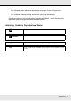
Chapter 4 Using the Control Panel Menu Menu Operations The menus are used as shown below. Menu List The following items and parameters can be set and executed in the Menu. See the reference pages for more details on each item.
Menu Item Media Setup Media Remaining See “The Media Setup Menu” on page 111. Parameter Remaining Setup On, Off Length 5.0 to 99.5 m (15 to 300 ft) Remaining Alert 1 to 15 m (4 to 50 ft) Print Remaining Length Print Select Media RIP Settings, 1 to 30 (media setting bank number) Customize Settings Current Settings Change settings for currently selected media. The options available depend on whether RIP Settings or a media setting bank is selected.
Menu Item Parameter Printer Setup Side Margin(Right) 3 to 25 mm (0.12 to 1.00 inch) See “The Printer Setup Menu” on page 115. Side Margin(Left) 3 to 25 mm (0.12 to 1.00 inch) Print Start Position 0 to 800 mm (0.00 to 32.
Menu Item Parameter Preference Date And Time MM/DD/YY HH:MM See “The Preference Menu” on page 119. Language Japanese, English, French, Italian, German, Portuguese, Spanish, Dutch, Russian, Korean, Chinese Unit: Length m, ft/in Alert Sound Setting On, Off Alert Lamp Setting On, Off Reset All Settings Yes, No See “The Reset All Settings Menu” on page 119. Details of the Menu The Media Setup Menu The Media Setup menu can be accessed directly by pressing the M button.
Select Media Parameter Explanation RIP Settings Choose the media settings used for printing. 1 to 30 (media setting bank number) If RIP Settings is selected, the media settings selected in the software RIP will be used. Select a number between 1 and 30 to use the settings in the corresponding media setting bank. Use Customize Settings to create media setting banks. Customize Settings Item Parameter Current Settings Explanation Change settings for currently selected media.
Item Parameter Explanation Tension Measurement Periodically Every page Choose Periodically or Every page to have the printer automatically monitor and adjust media tension during printing for optimal results, Off to disable automatic tension adjustment. Off Periodically is recommended in most circumstances.
Item Drying Time Per Pass Parameter Explanation 0 to 10 sec Select the time the print head pauses to allow drying after each pass. Choose from values between 0.0 and 10.0 seconds. The time needed for the ink to dry varies with ink density and the media used. If the ink blurs on the media, set a longer time for drying the ink. Increasing the drying time increases the time needed to print.
Print Media List Parameter Explanation Print Print the contents of media setting banks 1 to 30. The Printer Setup Menu indicates default settings. Item Parameter Explanation Side Margin(Right) 3 to 25 mm (0.12 to 1.00 inch) Choose the width of the right margin when media is loaded in the printer. For more information, see “Printable area” on page 76 Side Margin(Left) Print Start Position 3 to 25 mm (0.12 to 1.00 inch) Choose the width of the left margin when media is loaded in the printer.
Item Light Parameter Explanation Off/1 to 240 hours Choose the frequency—never (Off) or after 1 to 240 hours—and strength with which the printer performs head cleaning. Periodic head cleaning will not be performed while Off is selected. If a value between 1 and 240 hours is selected, auto head cleaning will be performed after the specified number of hours.
The Maintenance Menu The Maintenance menu can be accessed directly by pressing the # button. Item Parameter Explanation Nozzle Check Print A nozzle pattern will be printed. Inspect the pattern visually and perform head cleaning if you detect faint or missing colors. See “Checking for Clogged Nozzles” on page 81. All Nozzles Execute (Light)/ Execute (Medium)/ Execute (Heavy) Note the numbers of patterns that contain faint or missing colors and clean all or selected nozzles.
The Printer Status Menu These items track printer use and settings. Item Parameter Explanation Print Status Sheet Print Print a status sheet showing current printer settings, and the status of periodical replacement parts. Use this option to view a variety of information about the printer on a single sheet and help schedule the periodic replacement of parts. Firmware Version XXXXXXX,X_XX,XXXX View the printer Firmware Version. The Network Setup Menu indicates default settings.
The Preference Menu indicates default settings. Item Parameter Explanation Date And Time MM/DD/YY HH:MM Set the printer’s built-in clock. The time provided by the clock is used when printing logs and status sheets. Language Japanese Select the language used in the control panel display.
Chapter 5 Problem Solver When a Message is Displayed If one of the following messages is displayed, read and follow the instructions below. Messages What to do Prepare empty waste ink bottle. The waste ink bottle is getting full. Ready a new waste ink bottle. See “Options and Consumable Products” on page 129. Chip Unit Error Chip unit not recognized. Reattach or replace. Remove and reinsert the chip unit. If the same error still occurs, replace with a new chip unit.
Messages What to do Media Size Error Load correct size media. The media currently loaded is not the correct width. Raise the media loading lever and remove the media. The narrowest width supported by the printer is 300 mm (11.8 inches). Be sure the media is at least 300 mm (11.8 inches) wide. If this message is displayed even though the media is the correct width, the printer may print if Off is selected for Media Size Check. See “The Printer Setup Menu” on page 115.
The printer is not communicating with the computer. o Is the cable plugged in properly? Make sure the printer's interface cable is securely plugged into the correct terminal of the computer and the printer. Also, make sure the cable is not broken nor bent. If you have a spare cable, try connecting with the spare cable. o Does the interface cable specification match the specifications for the computer? Make sure the interface cable specifications match the specifications for the printer and the computer.
o Is the message Motor Self Adjustment displayed on the control panel's screen? The printer adjusts the internal motor. Wait for a while without turning off the printer. Test Pattern Does Not Print Correctly o Perform head cleaning. The nozzles may be clogged. Print a test pattern again after performing head cleaning. See “Head Cleaning” on page 82. o Has the printer been left unused for a long time? If the printer has not been used for a long time, the nozzles may have dried up and have been clogged.
o Is Data Width selected for Head Movement? Selecting Data Width for Head Movement in the setup menu increases print speed but may slightly reduce print quality. For better quality results, select Printer Full Width for Head Movement. See “The Printer Setup Menu” on page 115. o Have you compared the printing result with the image on the display monitor? Since monitors and printers produce colors differently, printed colors will not always match on-screen colors perfectly.
o Is the media creased or folded? Media that is creased or folded may rise from the platen and contact the print head, resulting in smudges or uneven colors. o Are the wiper, caps, or print head stained? Ink clots or lint around the wiper, caps, or print head may result in stains caused by a build-up of ink. Clean the affected area. See “Maintenance Around the Print Head” on page 84.
Removing Jammed Media Follow the steps below to remove jammed media. c Caution: Be careful not to trap your hands or fingers when opening or closing the front cover. Failure to observe this precaution could result in injury. 1. Open the front cover. 2. Turn off the printer. If a message is displayed and the printer will not turn off, unplug the power cable. 3. Remove the media holding plates, if installed. Important: Cease use of the printer if the media holding plates are deformed.
4. If the print head is over the media, move it away from the jam. Important: Move the print head only after removing the media holding plates. Contact with deformed media holding plates could damage the print head. 5. Raise the media loading lever. 6. Pull the media to the cutter groove and use a cutter to remove torn or creased portions. 7. Manually rewind the cut media. 8. Remove any media that remains inside the printer. 9. Turn on the power to the printer and perform a nozzle check.
Important: If the printer is left off for an extended period, the print head will be left uncapped and dry out, and will not print properly when printing resumes. Turning the printer on automatically caps the print head. Reload the media and resume printing. See “Loading Media” on page 28. Other Problems The control panel display keeps turning off. o Is the printer in sleep mode? Press the P button on the control panel to return to the normal state.
Chapter 6 Appendix Options and Consumable Products The following options and consumable products are available for use with your printer (as of September 2012). For the latest information, see the Epson website. Product Ink packs Part number Explanation Black T741100 Cyan T741200 Magenta T741300 Yellow T741400 Epson recommends the use of genuine Epson ink packs. Epson cannot guarantee the quality or reliability of non-genuine ink.
Supported Media The following media can be used with the printer. Print quality is greatly affected by the type and quality of media used. Choose a media suited to the task at hand. For information on use, refer to the documentation supplied with the media or contact the manufacturer. We recommend that you print a test run and check the results before purchasing media in large quantities. Important: Do not use media that is wrinkled, scuffed, torn, or dirty.
Moving and Transporting the Printer This section describes how to move and transport the product. Moving the Printer This section assumes that the product is being moved to another location on the same floor without traversing stairs, ramps, or lifts. See below for information on moving the printer between floors or to another building. See “Transport” on page 132. c Caution: Do not tilt the product more than 10 degrees forward or back while moving it.
Important: Use the casters on the dedicated printer stand to move the printer indoors a short distance over a level floor. They can not be used for transport. Post-Move Setup After moving the printer, follow the steps below to ready it for use. 1. Check that the new location is appropriate. See the Setup Guide. 2. Plug in the power cables and turn the printer on. See the Setup Guide. 3. Perform a nozzle check to check for clogged nozzles. See “Checking for Clogged Nozzles” on page 81. 4.
Specifications Table Printer Specifications Printing method On-demand ink jet Nozzle configuration 360 nozzles × 2 rows × 4 colors (black, cyan, magenta, yellow) Resolution (maximum) 720 × 1440 dpi Control code ESC/P raster (undisclosed command) Media feed method Friction feed Built-in memory 512 MB for Main 128 MB for Network Interface Hi-Speed USB-Compatible with the USB 2.0 Specification. 100BASE-TX/1000Base-T*1 Rated voltage AC 100 to 240V Rated frequency 50 to 60Hz Rated current 1.
Ink Specifications Type Dedicated ink pack Dye sublimation ink Black, Cyan, Magenta, Yellow Use by date See the date printed on the ink pack (at normal temperature) Print quality guarantee expiry 25 days (from the day the ink tank was refilled from the ink pack) Storage temperature Uninstalled: -20 to 40°C or -4 to 104oF (within a month at 40°C or 104oF) Installed: -20 to 35°C or -4 to 95oF (within a month at 35°C or 95oF) Transporting: -20 to 60°C or -4 to 140oF (within a month at 40°C or 104oF, w
FCC Compliance Statement For United States Users This equipment has been tested and found to comply with the limits for a Class A digital device, pursuant to Part 15 of the FCC Rules. These limits are designed to provide reasonable protection against harmful interference when the equipment is operated in a commercial environment.
Appendix A Where To Get Help New :See comments to select sections you need. The word "other" indicates products except for inkjet, SPC, Page, and SIDM. Contacting Epson Support Epson provides technical support and information on the installation, configuration, and operation of professional printing products through the Epson Preferred Limited Warranty Plan. Dial (888) 377-6611, 6 AM to 6 PM, Pacific Time, Monday through Friday. Days and hours of support are subject to change without notice.
Appendix B Software License Terms Open Source Software Licenses Bonjour This printer product includes the open source software programs which apply the Apple Public Source License Version1.2 or its latest version ("Bonjour Programs"). We provide the source code of the Bonjour Programs pursuant to the Apple Public Source License Version1.2 or its latest version until five (5) years after the discontinuation of same model of this printer product.
1.3 "Covered Code" means the Original Code, Modifications, the combination of Original Code and any Modifications, and/or any respective portions thereof. 1.
(a) You must retain and reproduce in all copies of Original Code the copyright and other proprietary notices and disclaimers of Apple as they appear in the Original Code, and keep intact all notices in the Original Code that refer to this License; and (b) You must include a copy of this License with every copy of Source Code of Covered Code and documentation You distribute or Externally Deploy, and You may not offer or impose any terms on such Source Code that alter or restrict this License or the recipient
3. Your Grants.
8. NO WARRANTY OR SUPPORT. The Covered Code may contain in whole or in part pre-release, untested, or not fully tested works. The Covered Code may contain errors that could cause failures or loss of data, and may be incomplete or contain inaccuracies. You expressly acknowledge and agree that use of the Covered Code, or any portion thereof, is at Your sole and entire risk.
11. Ownership. Subject to the licenses granted under this License, each Contributor retains all rights, title and interest in and to any Modifications made by such Contributor. Apple retains all rights, title and interest in and to the Original Code and any Modifications made by or on behalf of Apple ("Apple Modifications"), and such Apple Modifications will not be automatically subject to this License.
13.3 Independent Development. Nothing in this License will impair Apple's right to acquire, license, develop, have others develop for it, market and/or distribute technology or products that perform the same or similar functions as, or otherwise compete with, Modifications, Larger Works, technology or products that You may develop, produce, market or distribute. 13.4 Waiver; Construction.
The Original Code and all software distributed under the License are distributed on an 'AS IS' basis, WITHOUT WARRANTY OF ANY KIND, EITHER EXPRESS OR IMPLIED, AND APPLE HEREBY DISCLAIMS ALL SUCH WARRANTIES, INCLUDING WITHOUT LIMITATION, ANY WARRANTIES OF MERCHANTABILITY, FITNESS FOR A PARTICULAR PURPOSE, QUIET ENJOYMENT OR NON-INFRINGEMENT. Please see the License for the specific language governing rights and limitations under the License.
3. Altered versions--including, but not limited to, ports to new operating systems, existing ports with new graphical interfaces, versions with modified or added functionality, and dynamic, shared, or static library versions not from Info-ZIP--must be plainly marked as such and must not be misrepresented as being the original source or, if binaries, compiled from the original source.