Technical Reference Guide Product Overview Describes features and general specifications for the product. Setup Describes setup and installation of the product and peripherals. Application Development Information Describes how to control the printer and necessary information when you develop applications. Handling Describes how to handle the product.
Cautions • No part of this document may be reproduced, stored in a retrieval system, or transmitted in any form or by any means, electronic, mechanical, photocopying, recording, or otherwise, without the prior written permission of Seiko Epson Corporation. • The contents of this document are subject to change without notice. Please contact us for the latest information.
For Safety Key to Symbols The symbols in this manual are identified by their level of importance, as defined below. Read the following carefully before handling the product. You must follow warnings carefully to avoid serious bodily injury. WARNING CAUTION Provides information that must be observed to prevent damage to the equipment or loss of data. • Possibility of sustaining physical injuries. • Possibility of causing physical damage. • Possibility of causing information loss.
Warnings WARNING • To avoid risk of electric shock, do not set up this product or handle cables during a thunderstorm • Be sure to use the power cable complied with safety standards with a PE (power earth) terminal on the plug, and make sure to ground the product before use. Ignoring this may result in severe shock. • Never insert or disconnect the power plug with wet hands. Doing so may result in severe shock. • Handle the power cable with care. Improper handling may lead to fire or electric shock.
Cautions CAUTION • Do not connect cables in ways other than those mentioned in this manual. Different connections may cause equipment damage or fire. • Do not connect cables in ways other than those mentioned in this manual. Different connections may cause equipment damage or fire. • Be sure to set this equipment on a firm, stable, horizontal surface. The product may break or cause injury if it falls. • Do not use this product in locations subject to high humidity or dust levels.
About this Manual Aim of the Manual This manual was created to provide information on development, design, and installation of POS systems and development and design of printer applications for developers.
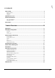
Contents ■ For Safety .............................................................................................................................. 4 Key to Symbols ........................................................................................................................................4 Warnings ..................................................................................................................................................5 Cautions ..........................................
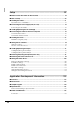
Setup .............................................................................................59 ■ When You Use This Printer for the First Time...................................................................... 59 ■ Flow of Setup ...................................................................................................................... 60 ■ Installing the Printer............................................................................................................
■ Printer Driver and Utility Function List .............................................................................. 131 Network Setting of the Printer ...........................................................................................................132 Setting the Printer ...............................................................................................................................136 Acquiring Printer Status.....................................................................
Maintenance of the TM-C3400.................................................199 ■ Necessary Information for an Administrator of the Printer ...........................................200 Printer Driver Functions ...................................................................................................................... 200 Destination for the Printer Driver Setting.......................................................................................... 201 Printer Setting ........................
Chapter 1 Product Overview Product Overview This chapter describes features and specifications of the product. Features The TM-C3400 is a 3-color ink jet printer that offers high speed easy operability and high reliability required for on-demand label printing.
Reliability • Pigment ink for excellent light-fastness and water-resistance. • High reliability system to prevent missing dots with auto nozzle check system installed. Software • Windows® printer driver is available. • The printer driver has the built-in barcode font, and available from .NET application. • Reprint function allows printing to the page that was not printed after solving paper jam error or an error of paper out. • The printer status can be obtained in network environment by EpsonNet SDK.
Chapter 1 Product Overview Product Configuration Interface • USB interface model (USB 2.0 high speed) • Ethernet interface model (100 Base-TX/10 Base-T) Color White (ENN8.
Parts Name and Function Front Control panel Release lever Paper ejection guide Paper ejection table Ink cartridge cover Paper ejection guide lock Paper ejection tray Power switch Roll paper cover Control panel Power LED Error LED Ink LED CUT button 16 Paper LED FEED button Power switch cover
Chapter 1 Product Overview Back F a n fo l d p a p e r Pa per feed 1 F a n fo l d p a p e r Connector (lower rear) USB Interface Model USB connector Power connector Cable hook Inlet (AC Adapter) AC Adapter Ethernet Interface Model Status sheet button Power connector Ethernet Connector Cable hook Inlet (AC Adapter) AC Adapter Connector cover 17
Power Switch Before turning on the printer, be sure to check that the AC adapter is connected to the power supply. CAUTION • When DIP switch 1 is OFF, the power is turned on after the POWER button has been pressed for 3 seconds. • When DIP switch 1 is ON, the printer settings are reset after POWER button has been pressed for 3 seconds. See "Setting the DIP Switches" on page 74 for DIP switch setting. Power Switch Cover Attaching the power switch cover prevents accidental pressing of the power switch.
Chapter 1 Product Overview Button FEED button • Feeds the paper continuously when media position detection is set to “No Detection”. ∗ The paper is fed by 15 mm if FEED button is pressed once. ∗ If the FEED button is held down, the paper is continuously fed until the button is released. (6 seconds at a maximum) • Feeds the paper to the print starting position when media position detection is set to “Detects Black Marks” or “Detects Margins Between Labels”.
INK (ink) LED: Red • Flashes when the ink is low or waste ink in the ink cartridge is nearly full. • Lights when it is time to replace the ink cartridge, when the ink cartridge is not installed or is not correctly installed, and when waste ink in the ink cartridge is full. • Lights off when ink in the ink cartridge is adequate. PAPER (paper out) LED: Red • Lights when the paper is not installed or is not correctly installed. • Lights off when the paper is correctly installed.
Chapter 1 Product Overview Status/Error Indications The printer status is displayed with combination of lighting and flashing of LED’s. When an error occurs, you can find out the cause and the remedy from the LED indication for the error. / : Lights / : Flashes : Off —: LED Power Error Ink Paper — — — No change Status Remedy Power on — Powering off — — — Charging ink 1 — Closing roll paper cover Saving or printing data Maintenance requirement The printer needs repair. 1.
/ : Lights / : Flashes : Off LED Power Error — Ink —: No change Status Paper Paper type error — Ink end Waste ink cartridge is full — 22 — — — Ink cartridge is not loaded Remedy Set specified papers. (See "Loading/Replacing the Paper" on page 76.) Replace the ink cartridge with a new one. (See "Replacing the Ink Cartridge" on page 141.) Ink cartridge is not loaded correctly Load the ink cartridge correctly. (See "Replacing the Ink Cartridge" on page 141.
Chapter 1 Product Overview Print without Missing Dots The printer has an auto nozzle checking system that detects missing dots, and performs the auto head cleaning if any dots are missing. Select from 4 modes that are available for different levels of requirements for print quality and movement. Sets this function from [Missing Dot Operation] on [Maintenance And Utilities] of the printer driver.
• Anti-missing Color Mode Does not perform missing dots check after printing each page, but checks missing dots while not printing. Prevents missing colors due to missing dots on the condition with adjoining 2 dots in above and below or 3 dots in all nozzles. Does not perform head cleaning to missing dots with less than 2 dots that are not adjoining. In the High Reliability Mode, printing takes more time since the missing dots check is performed after printing each page.
Chapter 1 Product Overview Software Various utilities are provided to system administrators and application developers. For details on how to get the software, see "Download" on page 130. Purpose Installing the printer driver Monitoring the printer Name Specifications Printer Driver Installs printer driver and executes port setting. Easy setup Installs printer driver, executes port setting and network setting of the printer.
Purpose Name Specifications EpsonNet SDK The software development kit for monitoring the printer via network. Sample Program This is the sample programs for using TM-C3400. (VB.NET, C++ is prepared for all programs. VB 6.0, C# is prepared for some programs.
Chapter 1 Product Overview Barcode/ two-dimensional code printing Barcode UPC-A, UPC-E, JAN 8 (EAN 8), JAN 13 (EAN 13), Code 39, ITF, Codabar, Code 93, Code 128, GS1-128, Barcode identification rate GS1 DataBar Omnidirectional, GS1 DataBar Truncated, GS1 DataBar Limited, GS1 DataBar Expanded ANSI rank D (based on Seiko Epson Corporation standard) Two-dimensional code printing Power supply Temperatures/ humidity PDF417, QR code, Maxi Code, S1 DataBar Stacked, GS1 DataBar Stacked Omnidirectional, GS1 Da
Hardware Requirements OS Microsoft Windows 2000 SP4 Microsoft Windows XP SP3 Microsoft Windows 2003 R2 SP2 Microsoft Windows Vista SP1 32-bit editions of those above only Computer Must support the following computers that run the above operating systems. • PC/AT compatible CPU Computers with a processor of 1 GHz or better are recommended. Intel Pentium/Celeron series, AMD Athlon/Duron family, or processors that are compatible with these are recommended.
Chapter 1 Product Overview Paper Specifications The following is the type and the size of paper specified for this printer. When using paper other than specified paper, paper feed accuracy, barcode detection accuracy, printing quality may be degraded or frequent paper jam may occur. Paper type Category Form Width Receipt Plain Media (Continuous paper) Fine Media {1.18 to 4.
Receipt This is continuous paper. Paper type Plain Media, Fine Media, PET Film Form Roll paper Paper width 30 to 108 mm Paper thickness 0.085 to 0.151 mm Roll paper core Outside diameter: 44.1 mm External diameter Maximum 101.6 mm Winding direction Printing face must be facing outside. Do not use the paper with a hole or cutout.
Chapter 1 Product Overview Black Mark Receipt Center of black marks Center of paper width Black mark length Interval of black marks Paper feeding direction Center of paper width Paper feeding direction Perforation position 0.
Paper type Plain Media, Fine Media, PET Film Form Fanfold paper Paper width 50 to 108 mm Black mark width 13 mm or more Black mark length 9 mm or more Black mark centering position 8.5 ± 1 mm Black mark interval 15 mm or more Paper thickness 0.119 to 0.151 mm Pitch of perforated line: 203.2 to 304.8 mm Form of perforated line Plain media : 1 mm uncut, 5 mm cut Number of folds Fine media : 1 mm uncut, 5 mm cut PET film : 0.6 mm uncut, 8.
Chapter 1 Product Overview Full-page Label Backing paper width 1 Edge cutoff Label width Backing paper Label area Edge cutoff Paper type Plain Media Label, Fine Media Label, Synthetic Media Label Form Roll paper Backing paper width 30 to 112 mm Label width 25.4 to 108 mm Edge cutoff on left/right side 2 ± 0.5 mm Paper thickness 0.128 to 0.195 mm Roll paper core Outside diameter: 44.1 mm External diameter Maximum 101.6 mm Winding direction Printing face must be facing outside.
Die-cut Label When removing right and left fringes only (Black Mark Die-cut Label) When removing all the fringes Backing paper width Edge R Edge cutoff Label width Edge cutoff Gap between labels Gap between labels Edge R Label length Label length Backing paper width Label Backing paper Label area Label chaff Label width Edge cutoff (edge) Edge cutoff (edge) Paper type Plain Media Label Form Roll paper Backing paper width 30 to 112 mm Label width 25.4 to 108 mm Label length 25.
Chapter 1 Product Overview Paper type Fine Media Form Roll paper Backing paper width 30 to 112 mm Label width 25.4 to 108 mm Label length 25.4 to 1117.6 mm When it is less than 15 {0.59”} to 25.4 {1”} mm, use the label of “When removing right and left fringes only” in the illustration. Gap between labels 3 to 5 mm Edge cutoff on left/right side 2 ± 0.5 mm Label edge R 2 mm or less Paper thickness 0.145 mm Roll paper core Outside diameter: 56.8 mm External diameter Maximum 101.
Paper type Synthetic Media Label Form Roll paper Backing paper width 30 to 112 mm Label width 25.4 to 108 mm Label length 50.8 to 1117.6 mm When it is less than 15 {0.59”} to 50.8 {2”} mm, use the label of “When removing right and left fringes only” in the illustration. Gap between labels 3 to 5 mm Edge cutoff on left/right side 2 ± 0.5 mm Label edge R 2 mm or less Paper thickness 0.195 mm Roll paper core Outside diameter: 44.1 mm External diameter Maximum 101.
Chapter 1 Product Overview Black Mark Die-cut Label Black mark length Center of black marks Center of paper width Interval of black marks Paper feeding direction Center of paper width Paper feeding direction Perforation position 5 mm or more ( W h e n u s i n g fa n fold paper) 1 Backing paper Label area Black mark width When removing all the fringes When removing right and left fringes only (Black Mark Die-cut Label) Paper width Paper width Label width Edge cutoff
Paper type Plain Media Form Roll paper Backing paper width 30 to 112 mm Label width 25.4 to 108 mm Label length 25.4 to 1117.6 mm When it is less than 15 {0.59”} to 25.4 {1”} mm, use the label of “When removing right and left fringes only” in the illustration. Gap between labels 3 to 5 mm Edge cutoff on left/right side 2 ± 0.5 mm Label edge R 2 mm or less Black mark width 13 mm or more Black mark length 9 mm or more Black mark centering position 8.
Chapter 1 Product Overview Paper type Fine Media Label Form Roll paper Backing paper width 30 to 112 mm Label width 25.4 to 108 mm Label length 25.4 to 1117.6 mm When it is less than 15 {0.59”} to 25.4 {1”} mm, use the label of “When removing right and left fringes only” in the illustration. Gap between labels 3 to 5 mm (5 mm for fanfold paper) Edge cutoff on left/right side 2 ± 0.
Paper type Synthetic Media Label Form Roll paper Backing paper width 30 to 112 mm Label width 25.4 to 108 mm Label length 50.8 to 1117.6 mm When it is less than 15 {0.59”} to 50.8 {2”} mm, use the label of “When removing right and left fringes only” in the illustration. Gap between labels 3 to 5 mm Edge cutoff on left/right side 2 ± 0.5 mm Label edge R 2 mm or less Black mark width 13 mm or more Black mark length 9 mm or more Black mark centering position 8.
Chapter 1 Product Overview Paper type Plain Media Label, Fine Media Label Form Fanfold paper Backing paper width 50 to 112 mm Label width 46 to 108 mm Label length 15 to 1117.6 mm Gap between labels 5 mm or more Edge cutoff on left/right side 2 ± 0.5 mm Label edge R 2 mm or less Black mark width 13 mm or more Black mark length 9 mm or more Black mark centering position 8.5 ± 1 mm Black mark interval 15 mm or more Paper thickness 0.145 to 0.161 mm Perforated line pitch: 203.
Wrist band This is under development. Paper type Wrist Band Form Roll paper Backing paper width 30 mm Black mark width 13 mm or more Black mark length 9 mm or more Black mark centering position 8.5 ± 1 mm Black mark interval Paper thickness Roll paper core Outside diameter: 44.1 mm External diameter Maximum 101.6 mm Winding direction Printing face must be facing outside.
Chapter 1 Product Overview Print Area and Cutting Position Receipt / Roll paper Top margin: 2.0 mm (typical value) Left and right margin: 2.0 mm (typical value) Bottom margin: 2.0 mm (typical value) 2.0 mm Paper width Center of paper width Paper feeding direction 1 2.0 mm 2.0 mm Auto-cut position 15.0 mm or more (When auto-cutting) 11.0 mm or more Auto-cut position Print area width 2.
Full-page Label / Roll paper Top margin (inside the label): 2.0 mm (typical value) Left and right margin (inside the label): 2.0 mm (typical value) Bottom margin (inside the label): 2.0 mm (typical value) 2.0 mm Paper width Center of paper width Paper feeding direction 15.0 mm or more (When auto-cutting) 11.0 mm or more Auto-cut position 2.0 mm Auto-cut position 2.0 mm 2.0 mm Print area width 2.0 mm Print area 2.
Chapter 1 Product Overview Die-cut Label / Roll paper 2.0 mm (typical value) Left and right margin (inside the label): 2.0 mm (typical value) Bottom margin (inside the label): 2.0 mm (typical value) Paper width Center of paper width 2.0 mm 1.5 mm Top margin (inside the label): Paper feeding direction 3.0 mm 11.0 mm or more 18.0 mm or more (When auto-cutting) Auto-cut position 1 2.0 mm 1.5 mm Auto-cut position 2.0 mm 2.0 mm Print area width 2.0 mm Print area 2.
Top margin: 2.0 mm (typical value) Left and right margin: 2.0 mm (typical value) Bottom margin: 2.0 mm (typical value) Paper width Center of paper width 2.0 mm Black Mark Receipt / Roll paper Paper feeding direction 11.0 mm or more 15.0 mm or more (When auto-cutting) Auto-cut position 2.0 mm 2.0 mm Auto-cut position Print area width 2.
Chapter 1 Product Overview Bottom margin: 2.0 mm (typical value) Center of paper width Paper width 11.0 mm or more Perforated line Auto-cut position 2.0 mm 2.0 mm Auto-cut position Paper feeding direction 1 Interval of perforated lines: 203.2 mm to 304.8 mm 2.0 mm (typical value) Issuing pitch: 15.0 mm or more (When auto-cutting) Left and right margin: 2.0 mm 2.0 mm (typical value) 0.5 to 1.0 mm Top margin: 2.0 mm Black Mark Receipt / Fanfold paper Perforated line Auto-cut position 2.
Black Mark Die-cut Label / Roll paper 2.0 mm (typical value) Left and right margin (inside the label): 2.0 mm (typical value) Bottom margin (inside the label): 2.0 mm (typical value) Center of paper width 2.0 mm Paper width 1.5 mm Top margin (inside the label): Paper feeding direction 18.0 mm or more (When auto-cutting) 2.0 mm Auto-cut position 1.5 mm 11.0 mm or more Auto-cut position 2.0 mm 1.5 mm 2.0 mm Auto-cut position 2.0 mm 2.
Chapter 1 Product Overview Black Mark Die-cut Label / Fanfold paper Bottom margin (inside the label): 2.0 mm (typical value) Paper width 11.0 mm or more 2.0 mm 5.0 mm or more Perforated line Auto-cut position 2.0 mm 3.0 to 3.5 mm 2.0 mm 3.0 to 3.5 mm Auto-cut position Paper feeding direction Issuing pitch: 18.0 mm or more (When auto-cutting) Center of paper width 1 Interval of perforated lines: 203.2 mm to 304.8 mm 2.0 mm (typical value) 1.5 to 2.
Paper Ejection Tray Black Mark Receipt Black Mark Die-cut Label Paper type Plain Media, Fine Media, PET Film Paper form Fanfold paper Paper size Width 76 to 105 mm × length 54 to 148 mm Paper thickness 0.119 to 0.151 mm Paper type Plain Media, Fine Media Paper form Fanfold paper Paper size Width 76 to 105 mm × length 54 to 148 mm Paper thickness 0.145 to 0.161 mm • The paper ejection tray cannot store multiple sheets of roll paper.
Chapter 1 Product Overview Electrical Characteristics Power supply Power supplied by AC adapter accessory (PS-180) Input voltage (rated) North America / Japan: AC 100 to 125V Other countries: Frequency (rated) 50 Hz to 60 Hz Power consumption Operating Approximately 26W Stand-by Approximately 5W When power is OFF Approximately 0.5W AC 100 to 240V 1 • Use the dedicated AC adapter included in the product package. • Use CAT5e or FTP cable for the Ethernet cable.
Reliability Life Print head 6,000 million shots/nozzle Paper feed mechanism 1,500,000 pages or the number of pages that reaches the following paper length fed.
Chapter 1 Product Overview Environmental Conditions Item Temperatures/ humidity Specification Printing 10 to 35°C, 20 to 80%RH (no condensation) Humidity (%) Temperatures (°C) 1 Barcode printing 15 to 35°C, 20 to 80%RH (no condensation) Storage When packed (ink not loaded): -20 to 60°C, 5 to 85%RH (no condensation) -20°C or 60°C: up to 120 hours Ink loaded: -20 to 40°C -20°C: up to 120 hours 0 to 30°C: up to 6 months 40°C: up to a month Pressure (elevation) Acoustic noise Op
External Dimensions • Height: 261 mm • Width: 255 mm • Depth: 275 mm 300 255 275 261 457 (when the paper ejection tray is extended) 388 (when the paper ejection tray is shortend) 300 [Unit: mm] 54
Chapter 1 Product Overview Power Supply Unit (PS-180) 136 68 32 [Unit: mm] Electric characteristics Input conditions Input voltage (rated): 90 to 264VAC (100VAC -10% to 230VAC +15%) Frequency (rated): 50/60 Hz ± 3 Hz Power consumption (rated): 100VA Output conditions Output voltage (rated): 24VDC ± 5% Output current (rated): 2.0A Output electric power (rated): 48VA Output peak current: 4.5A Case specifications Dimensions 68 × 136 × 32 mm {2.68 × 5.35 × 1.
Restrictions Printer environment • Drivers for TM printers (APD, OPS/JavaPOS) of Seiko Epson Corporation cannot be used for this printer. The TM-C3400 printer driver can be installed and used on a computer with the APD and OPS/JavaPOS installed. Installation environment for the printer driver • The printer driver for Ethernet interface model cannot be installed with a USB interface model printer connected.
Chapter 1 Product Overview Paper • When using a full-page label, remove the ejected label each time the printing is finished. Otherwise, a part of printed label may be cut, or a cutter error may occur. (See "Status/Error Indications" on page 21.) • When cutting the full-page label, adhesive from labels may stick to the fixed blade of the autocutter, which may prevent the autocutter from cutting paper cleanly. If this happens, clean the cutter blade. For details, see "Cleaning the Autocutter" on page 191.
Chapter 2 Setup Setup This chapter describes setup and installation of the product and peripherals. When You Use This Printer for the First Time Ink charging and media position detection setting are necessary before you use this printer for the first time. Follow the steps below. 1 Load the roll paper. 2 Turn on the printer. 3 Load a new ink cartridge. For details, see Loading/Replacing the Roll Paper on page 76. 2 For details, see Loading/Replacing the Ink Cartridge on page 63.
Flow of Setup This chapter consists of the following sections along with the setup flow of the product and peripherals. 1. Installing the Printer (page 61) 2. Connecting the Power Supply Unit (PS-180) (page 62) 3. Loading/Replacing the Ink Cartridge (page 63) 4. Connecting the Printer to the Host Computer (page 65) 5. Installing the Driver (page 67) 6. Setting the DIP Switches (page 74) 7. Loading/Replacing the Paper (page 76) 8. Attaching/Adjusting the Paper Ejection Tray (page 96) 9.
Chapter 2 Setup Installing the Printer Install the printer in an appropriate location with sufficient space around it. Important Notes on Installation 261 2 100 275 255 [Unit: mm] • The printer must be installed horizontally. • Leave enough space in front of the printer for the ink cartridge cover and the roll paper cover to be fully opened. • Do not place the printer in a dusty location. • Protect the printer from heavy impacts. They may cause defective print.
Connecting the Power Supply Unit (PS-180) Use the PS-180 or an equivalent product as the power supply unit. WARNING • Always use the EPSON PS-180 or an equivalent product as the power supply unit. Using a nonstandard power supply can result in electric shock or fire. • Should a fault ever occur in the EPSON PS-180 or equivalent product, immediately turn off the power to the printer and remove the power supply cable from the wall socket. Use the AC cable that meets safety standards of each country.
Chapter 2 Setup Loading/Replacing the Ink Cartridge • When the ink cartridge is installed for the first time, be sure to install the roll paper first, and turn on the printer, and then install the ink cartridge. See Loading/Replacing the Roll Paper on page 76 for how to load the roll paper. • Always use the EPSON SJIC15P as the ink cartridge. • Do not open the package of the ink cartridge until you are ready to load it in the printer. 1 Load the roll paper included in the product package.
6 Close the ink cartridge cover. When the ink cartridge is loaded for the first time, it takes approximately 8 minutes for ink charging. Do not open the roll cover or the ink cartridge cover of the printer, or press the Power switch or the FEED button. The INK LED (red) turns off. The POWER LED (green) starts flashing when the ink charge starts. Charging is finished when the POWER LED flashing becomes lighting.
Chapter 2 Setup Connecting the Printer to the Host Computer For USB Interface Model Connect the printer to the host computer by the USB cable. • Do not turn the power on until the printer driver is installed. • Make sure to use the USB cable included with the printer. Insert the USB cable to the USB connector on the lower rear of the printer and arrange it as shown below. Make sure to put the USB cable through the cable hook as shown in the figure below to prevent the cable from coming unplugged.
For Ethernet Interface Model Connect the printer to a network by a LAN cable via a hub. CAUTION 1 2 • When LAN cables are installed outdoors, make sure devices without proper surge protection are cushioned by being connected through devices that do have surge protection. Otherwise, the devices can be damaged by lightning. • Never attempt to connect the standard telephone line cable to the 10/100BASE-T LAN connector. Open the connector cover on the rear of the printer.
Chapter 2 Setup Installing the Driver The following two methods can be selected when installing the printer driver. • Installation using Easy setup: Described in this manual. • Installation from the printer driver file: Not described in this manual. Execute the installer of the printer driver, and follow the instructions on the screen to install the printer driver.
2 3 4 5 Click [Local] for USB interface model. Click [Install]. Make sure of the connection to the computer when the following window appears, then turn the power on. Click [Exit]. This is the end of driver installation.
Chapter 2 Setup For Ethernet Interface Model When the network setting such as IP address setting on TM-C3400 was already made, the setting is applied. The setting can not be changed. Follow the steps below to install the printer driver and execute the network setting. 1 Turn the printer on. 2 Double-click the icon for Easy Setup “EPSetup.exe”. 3 Click [Network] for Ethernet Interface Model. 2 4 Click [Install].
5 The printers available are displayed. Select the printer to install, and click [Next]. When the IP address was already set in the printer, go to step 9. 6 The method for acquiring IP address is displayed. Select the method you want to take, and click [Next]. When you select “Manual”, enter the IP address.
Chapter 2 Setup 7 8 Checking the settings is displayed. If the settings are correct, click [Next]. If you want to change IP address setting, click [Back]. Completed notice of the communication setting is displayed. Click [Next].
9 Enter the Printer Name and click [Next]. Do not check the box of [Print test page]. 10 Select which installed printer driver to use as a default printer, and click [Next]. The printer driver will be installed after clicking [Next].
Chapter 2 Setup [Finish]. 11 Click It terminates “EpsonNet EasyInstall”. 2 12 Click [Exit]. This is the end of driver installation and network setting.
Setting the DIP Switches Change the DIP switch settings in the following cases. • When attaching the power switch cover to prevent the power switch from being pressed • When switching the paper type between roll paper and fanfold paper (The default setting is roll paper) • When changing the volume of the buzzer Setting Procedure Follow the steps below to change the DIP switch settings. Turn the power off before removing the DIP switch cover. Otherwise, a short-circuit may cause the printer to malfunction.
Chapter 2 Setup Function of the DIP Switches SW Function 1 Operation of the power switch 2 Internal use 3 Paper selection 7 Internal use 8 Buzzer volume ON OFF Factory settings Reset Power ON/OFF OFF Fixed to OFF (Do not change) Fanfold paper Roll paper Fixed to OFF (Do not change) High Low OFF OFF OFF OFF When attaching the power switch cover to prevent the power switch to be pressed, set DIP switch 1 to ON.
Loading/Replacing the Paper Follow the steps below to load the paper for the first time, change classification or type of the paper (roll paper or fanfold paper) or replace the paper. Loading the paper is different depending of the type of the paper to use roll paper or fanfold paper. • For roll paper, see Loading/Replacing the Roll Paper on page 76. • For fanfold paper, see Loading/Replacing Fanfold Paper on page 86. • Use paper that meets the printer specification.
Chapter 2 Setup 1. Removing the paper This procedure is not required when the paper is initially loaded to the printer. For roll paper 1 Press down the release lever, and pull it to the front to open the roll paper cover. Remove the roll paper or the roll paper core if any. 2 2 Close the roll paper cover.
For fanfold paper 78 1 Open the fanfold paper cover. 2 Remove the remaining paper.
Chapter 2 Setup 2. Setting for media position detection This procedure is not required when media position detection is not changed. When paper remains in the printer, media position detection cannot be set. Be sure to remove the paper before turning on the printer. 1 Turn the power on. 2 Remove the paper in the printer. 3 4 Display the printer driver window. (See How to Use the Printer Driver on page 152 for how to display the driver window.
3. Removing the paper feed guide This procedure is not required when the paper is initially loaded to the printer or the paper type is not changed (roll paper/fanfold paper). Attach the paper feed guide to the printer only when using the fanfold paper. Be sure to remove the paper feed guide when using the roll paper. 1 2 3 80 Press down the release lever, and pull it to the front to open the roll paper cover.
Chapter 2 Setup 4. Adjusting roll paper guide/paper ejection guide This procedure is not required when paper width is not changed. 1 2 3 Press down the release lever, and pull it to the front to open the roll paper cover. 2 Unlock the roll paper guide. Push the paper guide on the left in the direction of the arrow, and load the roll paper with the printing side up.
4 Lock the roll paper guide. 5 Release the lock of the paper ejection guide with a fine-tipped object. 6 Align the paper ejection guide with the roll paper width.
Chapter 2 Setup 7 Lock the paper ejection guide. 8 Close the roll paper cover.
5. Loading the paper and turning on the printer Steps 1 to 3 below are not necessary after performing Step 4. Adjusting roll paper guide/paper ejection guide on page 81. 1 2 84 Press down the release lever, and pull it to the front to open the roll paper cover. Load the roll paper with the printing side up.
Chapter 2 Setup 3 4 Close the roll paper cover while aligning the roll paper with the paper ejection guide. Turn the power on. The roll paper is automatically fed. When paper set operation at the paper cover close is set as “Media Loading Method (with Cutting)” of [Media Loading Settings] on [Maintenance And Utilities] tab on the printer driver, paper is automatically cut after the paper is fed. This is the end of loading of the roll paper.
Loading/Replacing Fanfold Paper Follow the steps below to load the fanfold paper. • Loading the paper for the first time: 2 to 5 • Using the paper completely (loads same type of paper): 1, 5 • Changing paper type or classification: 1 to 5 1. Removing the paper (page 87) 2. Setting for media position detection (page 89) 3. Attaching the paper feed guide (page 90) 4. Adjusting paper ejection guide/fanfold paper guide (page 92) 5.
Chapter 2 Setup 1. Removing the paper This procedure is not required when the paper is initially loaded to the printer. For roll paper 1 Press down the release lever, and pull it to the front to open the roll paper cover. Remove the roll paper or the roll paper core if any. 2 2 Close the roll paper cover.
For fanfold paper 88 1 Open the fanfold paper cover. 2 Remove the paper left.
Chapter 2 Setup 2. Setting for media position detection This procedure is not required when media position detection is not changed. • When paper remains in the printer, media position detection cannot be set. Be sure to remove the paper before turning on the printer. • The changed setting of the media position detection is saved in the NV memory of the printer when the printer is turned off. Be sure to turn off the printer to enable the setting. 1 Turn the power on. 2 Remove the paper in the printer.
3. Attaching the paper feed guide This procedure is not required when paper type (roll paper/fanfold paper) is not changed. Make sure to attach the paper feed guide when using fanfold paper. 1 2 90 Open the fanfold paper cover and take out the paper feed guide. Press down the release lever, and pull it to the front to open the roll paper cover.
Chapter 2 Setup 3 4 Insert the paper feed guide into the grooves inside of the roll paper cover to attach it. Close the roll paper cover.
4. Adjusting paper ejection guide/fanfold paper guide This procedure is not required when paper type (roll paper/fanfold paper) is not changed. 92 1 Release the lock of the paper ejection guide with a fine-tipped object. 2 Slide the paper ejection guide as wide as possible. 3 Lock the paper ejection guide.
Chapter 2 Setup 4 5 Open the fanfold paper cover and release the lock of the fanfold paper guide. Align the fanfold paper guide with the fanfold paper width. 2 6 Lock the fanfold paper guide.
5. Loading the fanfold paper and turning on the printer 1 2 Turn the power on. After the Power LED stops flashing and lights, insert the paper into the paper slot with the print surface facing upward until it is pulled into inside the printer (approximately 100 mm). The paper is automatically fed.
Chapter 2 Setup 4 Close the fanfold paper cover. This is the end of loading of the fanfold paper.
Attaching/Adjusting the Paper Ejection Tray If you attach the paper ejection tray, you can temporarily store the printed paper in the tray. Follow the steps below to install/adjust the ejection tray. • Paper may not stay in the paper ejection tray depending on the paper curl and length. • When the fanfold paper is used, the several printed papers can be stored in the ejection tray. See Paper Ejection Tray on page 50 for the numbers of the fanfold paper that can be stored in the ejection tray.
Chapter 2 Setup 3 Slide the bottom tray to align it with the paper length. 4 Lock the paper ejection tray.
Attaching the Power Switch Cover Attaching the power switch cover prevents accidental pressing of the power switch. Before attaching the power switch cover, set DIP switch 1 to ON. (For details, see “Setting the DIP switches”Function of the DIP Switches on page 75.) The printer power can then be switched by turning the AC supply on and off, and you can also control the printer power with a device such as a distribution board In this case, the power switch is used to reset the printer.
Chapter 2 Setup To switch the power switch by inserting a long, thin object into a hole Attach the power switch cover after punching the hole in it. The hole cannot be punched in the power switch cover after it is attached to the printer. 1 2 Punch a hole in the power switch cover by pushing the middle of it with a hard, fine-tipped object. Push the power switch cover onto the power switch of the printer.
Setting the Printer Driver The following functions can be set on the printer driver. Printer setting • Missing Dot Operation Settings • Notification Settings • Media Loading Settings • Media Position Detection • Panel Button Settings Driver setting • Setting for EPSON Status Monitor 3 • Settings For Handling Media After Print Missing Dot Operation Settings The following are the modes when dots are missing. ([Anti-missing Read Mode] is set as a default setting.
Chapter 2 Setup 4 5 The [Missing Dot Operation Settings] window is displayed. Select [Missing Dot Operation Settings] and click [Next]. Select the setting mode. See Print without Missing Dots on page 23 for which mode to select. After selecting the mode, click [OK]. Click [Cancel] to terminate without performing the [Missing Dot Operation Settings]. 6 Setting is completed. Click [OK] to finish.
Void image registration Specifies the print image on High Reliability Mode (Void Image Print) when dots are missing. The default void printing is all-in-black printing with height of 25.4 mm and user can change this to another image file. 1 Turn the printer on. 2 Display the printer driver window. 3 4 102 (See How to Use the Printer Driver on page 152 for how to display the driver window.) Select the [Maintenance And Utilities] tab and click [Missing Dot Operation].
Chapter 2 Setup 5 Click [Browse] to select the image to print. Click [Register] to register the image to print. Click [Cancel] to terminate without performing the [Void Image Registration]. A bitmap image of 737 pixel width and 78 pixel to 180 pixel height can be registered as a void image. 6 2 The void image registration is completed. Click [OK].
Void image test print Perform a test print of the image to print when dot missing occurs in the High Reliability Mode (Void Image Print). 1 Turn the printer on. 2 Display the printer driver window. 3 (See How to Use the Printer Driver on page 152 for how to display the driver window.) Select the [Maintenance And Utilities] tab and click [Missing Dot Operation]. 4 Select [Void Image Test Print] and click [Next]. 5 Click [Test Print] to start test print.
Chapter 2 Setup 6 Click [OK] to finish the test print.
Notification Settings Sets following notification setting. • Beep Notification Setting at an Error Selects beep notification (sounds buzzer or not) when error occurs. (Default setting is [Beep]. The user does not need to change when using with default setting.) • LED Notification Setting at Ink Low Selects LED notification (lights LED or not) when ink level is low. (Default setting is [LED On]. The user does not need to change when using with default setting.
Chapter 2 Setup 5 Select notification setting, and click [OK]. Click [Cancel] to terminate without performing the [Notification Settings]. Beep Notification Setting an Error 6 LED Notification Setting at Ink Low Notification Setting at a Paper Size/Type Error Setting is completed. Click [OK] to finish.
Media Loading Settings Sets paper feed movement to the print starting position when turning the printer power on or the roll paper cover is closed. The following is the movements to feed the paper to the print starting position when turning the printer power on or the roll paper cover is closed. (Default setting is [Media Loading Method (with Cutting)]. The user does not need to set when using with default setting.
Chapter 2 Setup 4 5 The [Media Loading Method Settings] window is displayed. Select your choice and click [Next]. Sets paper feed to the print starting position and click [OK]. Click [Cancel] to terminate without performing the [Media Loading Method Settings]. Paper Set Operation at the Start up 6 2 Paper Set Operation at the Paper Cover close Setting is completed. Click [OK] to finish.
Media Position Detection The following 3 types of media position detection is set on this printer. This is set from [Media Position Detection] on [Maintenance And Utilities] tab. • No Detection Detects paper presence only, and does not adjust the paper position. • Detect Blackmarks on Die-cut Labels When using Black Mark Die-cut Label, adjusts printing position and autocutting position to the top of the black mark.
Chapter 2 Setup No Detection Detect Blackmarks on Die-cut Labels Detect Blackmarks on Continuous Paper Detect Margins Between Labels Black Mark Receipt — - √ — Black Mark Die-cut Label — √ — √ — — √ — Paper type to use Fan-fold Media Black Mark Receipt (Wrist Band) √: Used, —: Not Used 2 111
Panel Button Settings Enable/disable the panel buttons of this printer. The setting can be made for the following buttons. • Feed Button • Cut Button Follow the steps below to make the setting. 1 Turn the printer on. 2 Display the printer driver window. 3 Select [Maintenance And Utilities] tab, and click [Panel Button Settings]. 4 112 (See How to Use the Printer Driver on page 152 for how to display the driver window.) The [Panel Button Settings] window is displayed.
Chapter 2 Setup 5 Select Enable/Disable the panel button, and click [OK]. Click [Cancel] to terminate without performing the [Panel Button Settings]. Feed Button 6 Cut Button Setting is completed. Click [OK] to finish.
Setting EPSON Status Monitor 3 The following is available when EPSON Status Monitor 3 is enabled. • The printer window is automatically displayed during printing to check printing status. • Error information is displayed when an error occurs during printing. The EPSON Status Monitor 3 will not be activated if an error occurs when not printing. • Keeps icon on the task tray so that user can check when needed.
Chapter 2 Setup Enable or disable setting of EPSON Status Monitor 3 EPSON Status Monitor 3 is disabled by default. Follow the steps below to enable EPSON Status Monitor 3. 1 Turn the printer on. 2 Display the printer driver window. 3 Select [Driver Utilities] tab and click [Driver Preferences]. 4 (See How to Use the Printer Driver on page 152 for how to display the driver window.) The [Driver Preferences] window is displayed. Check the box of [Use EPSON Status Monitor 3] and click [OK].
Error display setting for EPSON Status Monitor 3 Follow the steps below to make setting of error display for EPSON Status Monitor 3. 1 Turn the printer on. 2 Display the printer driver window. 3 Select [Driver Utilities] tab and click [Monitoring Preferences]. 4 (See How to Use the Printer Driver on page 152 for how to display the driver window.) The [Monitoring Preferences] window is displayed. Click on the box of your choice, , and click [OK].
Chapter 2 Setup Displaying the icon Keeps icon on the task tray so that user can check as needed. The icon is not displayed when default setting. Follow the steps below to display the icon. 1 Turn the printer on. 2 Display the printer driver window. 3 Select [Driver Utilities] tab and click [Monitoring Preferences]. 4 (See How to Use the Printer Driver on page 152 for how to display the driver window.) The [Monitoring Preferences] window is displayed.
Setting the Post-Printing Movements The following post-printing movement can be set on this printer. Sets from [Settings For Handing Paper After Print] on [General] of the printer driver. • Auto Cut: After Every Page/Only After Last Page/After Specified Number of Pages After printing, the paper is fed to the position where autocutting is possible and feeding stops after autocutting. When resuming printing, the paper is fed in the reverse direction to the printing position and then printing resumes.
Chapter 2 Setup Setting [Settings For Handing Paper After Print] depending on the paper type and paper cutting Sets “post-printing movements” depending on the type of the paper and how the paper is cut.
Printer Diver Settings Printer Operating No Auto Cut Paper type to use Auto Cut Stop at the Print End Position Feed To Cut Position Feed To Peel Off Position Cuts automatically √ — — — Cuts automatically √ — — — Peels the label by user Backing paper is not cut — — — √ Cuts the backing paper by pressing CUT button — √ √ — Tears along perforated line manually — — — √ Cuts automatically √ — — — Paper cutting method Black Mark Receipt Fan-fold Media Black Mark Die-cut Lab
Chapter 2 Setup For Ethernet Interface Model and shared printer For Ethernet Interface Model and shared printer, the printing is performed from another application before user cuts the paper and paper jam may occur by drawing the paper into the printer. Set [Auto Cut] or cut manually by pressing CUT button to prevent paper jam.
Printer Diver Settings Printer Operating No Auto Cut Paper type to use Auto Cut Stop at the Print End Position Feed To Cut Position Feed To Peel Off Position Cuts automatically √ — — — Cut by pressing CUT button — √ √ — Tears along perforated line manually* — — — √ Cuts automatically √ — — — Peels the label by user Backing paper is not cut* — — — √ Cuts the backing paper by pressing CUT button — √ √ — Tears along perforated line manually* — — — √ Cuts automatically
Chapter 3 Application Development Information Application Development Information This chapter describes how to control the printer and gives information useful for printer application development. Overview The following is provided to use this printer. ❏ The dedicated printer driver for Windows is available. The reprint function is implemented in the printer driver.
Sample Program Refer to TM-C3400 sample program to develop the application using this printer. ❏ Conditions to using TM-C3400 sample program • Use Die-cut Label (108 × 174.8 mm). • Change settings to [Detect Margin Between Labels] on [Media position detection Setting] of the printer driver. • Some sample programs use SNMP TRAP. The Trap function of the printer is set with EpsonNet SDK when installing. Therefore, enable the Trap function before installing the EpsonNet SDK.
Chapter 3 Application Development Information Printer Model C++ C# VB.NET VB6.0 Application Specification Ethernet Basic Program name USB Level Language Step 5 Notifying the printer status from the printer to the application When the condition of the p r i n t e r i s c ha n g e d , eve n t i s caused by SNMP from the application and executes error handling. — √ √ — √ — Complete basic features The program combined from Step 1 to 5.
EpsonNet SDK EpsonNet SDK is the API for the Epson network printer, and also supported by this printer. The network setting is checked but setting can not be executed on this printer. This is to use for developing the application to monitor the printer on the network of this printer. The EpsonNet SDK operates under Win32. It can operate also under .NET, but not is not supported officially. EpsonNet SDK is used for Simple Viewer for the tool to monitor the printer on the network.
Chapter 3 Application Development Information Setting Procedure When the EpsonNet SDK has already been installed, uninstall it first. Follow the steps below to make the setting for the EpsonNet SDK, and then install it again. 1 Edit “setting.ini” in the Install Disk of the EpsonNet SDK. 2 Install the EpsonNet SDK.
Utilities and Manuals The several kinds of utilities and manuals other than the printer driver are available for this printer. Name Package file name Manual Printer Driver c34d32_xxxx.exe TM-C3400 Technical Reference Guide Easy Setup EPSetup.exe None Install Assistant c34ia_xxxe.exe TM-C3400 Install Assistant User's Manual Printer Setting c34ps_xx.exe TM-C3400 Printer Setting Guide EpsonNet Simple Viewer ensvxx.exe EpsonNet Simple Viewer User's Manual EpsonNet Config encwxxx.
Chapter 3 Application Development Information Printer Setting This is to change settings at one time for several printer drivers in the network. For USB interface model, the USB serial number can also be edit. For using this utility, the printer driver is needed to be installed. • Only the driver settings saved in NV memory in the printer can be copied. The driver settings saved in the computer can not be copied. See "Printer Driver and Utility Function List" on page 131 for the settable items.
Download Drivers, utilities, and manuals can be downloaded from one of the following URLs. For customers in North America, go to the following web site: http://www.epsonexpert.com/ and follow the on-screen instructions. For customers in other countries, go to the following web site: http://www.epson-pos.
Chapter 3 Application Development Information Printer Driver and Utility Function List Printer Driver Utility Easy setup [Driver Utilities] tab [Maintenance And Utilities] tab EPSON Status Monitor 3 Install Package Install Assistant EpsonNet Config EpsonNet Web Config Printer Setting EpsonNet Simple Viewer EpsonNet SDK Driver Printer (1: 1 pc, m: two or more) 1 — 1 1 — — m 1 m m m Computer (1: 1 pc, m: two or more) 1 1 — 1 m m 1 1 1 1 1 Driver installation √ — — —
Network Setting of the Printer Referring the setting value Driver Utility 132 [Maintenance And Utilities] tab EPSON Status Monitor 3 Install Package Install Assistant EpsonNet Config EpsonNet Web Config Printer Setting EpsonNet Simple Viewer EpsonNet SDK Admi ni stration i n fo r ma tion [Driver Utilities] tab Basic Easy setup Driver IP Address √ X X X √ √ √ √ √ √ √ MAC Address √ X X X X √ √ √ √ √ √ Hardware Version X X X X X X √ √ X X X Software Version
Chapter 3 Application Development Information Setting value Acquiring Basic Setting TCP/IP Basic (wired) Acquiring Network Setting EpsonNet Config EpsonNet Web Config EpsonNet Web Config can not be used for the printer with default condition since IP address is not available.
Basic IP Trap 1/2 EpsonNet Web Config Use Bonjour X X √ √ Bonjour Name X X √ √ Bonjour Printer Name X X √ √ Enable universal plug and play function √ √ √ √ Device name √ √ √ √ Location √ √ X X Read Only √ √ √ √ Read/Write √ √ √ √ Enable IP Trap 1/2/3/4 √ √ √ √ Address √ √ √ √ Community √ √ √ √ Port Number √ √ √ √ Time Basic Date/time/time zone and etc.
Password Restores to the factory default setting Acquiring User recognition Setting Administrator setting Basic Acquiring Timeout Setting EpsonNet Config EpsonNet Web Config Chapter 3 Application Development Information LPR √ √ √ √ RAW (Port9100) √ √ √ √ User recognition function (administrator name) X X √ √ Installation place (location) X X √ √ Administrator Password √ √ √ √ (The printer is restored to the factory default setting also by turning on the printer while pre
Acquiring Setting Acquiring Bi-directional printing position adjustment √ X X X Paper feed adjustment √ X X X Print Start Position Adjustment (Roll Paper) √ X X X Print Start Position Adjustment (Margins between labels/ black marks/autocutter) √ X X X Auto Cut Position Adjustment √ X √ √ Print Start Position Adjustment √ X √ √ Media Loading Method at Start up √ X √ √ Media Loading Method at Media Cover close √ X √ √ Beep Notification Setting at an Error √ X √ √
Chapter 3 Application Development Information Printer status EpsonNet SDK Self printing EpsonNet Simple Viewer Error EpsonNet Web Config Ink Status EPSON Status Monitor 3 Acquiring Printer Status Ink color √ √ √ √ Ink Levels √ √ √ √ Communication error X X √ √ Autocutter error X X √ √ Fatal error X X √ √ Cover open X X √ √ Paper jam X X √ √ It is the time to replace the ink cartridge.
EpsonNet Web Config EpsonNet Simple Viewer X X √ Maintenance requirement is near. X X √ Disposal ink overflow is near. X X √ Cleaning X X √ Factory default setting X X √ Shutting down X X √ 138 EpsonNet SDK EPSON Status Monitor 3 It is the time to replace the ink cartridge.
Chapter 3 Application Development Information Application Specification to Develop This section describes specifications to develop printing application of this printer. Character Size to Print Make sure to set the font size with 2 dots in vertical direction (example: 8 pt or more for Arial) to use on the user’s application to avoid mistakes of the printed characters.
Chapter 4 Handling Handling This chapter describes basic handling of the printer. Replacing the Ink Cartridge Printing can not be made if any of the three color inks ends. When the ink ends, the INK LED lights. Follow the steps below to replace the ink cartridge. • Always use the EPSON SJIC15P as the ink cartridge. • Do not open the package of the ink cartridge until you are ready to load it in the printer.
3 Pull out the empty ink cartridge to remove it. Do not leave the printer without ink cartridge. Otherwise, the print head may dry and clog. CAUTION 4 Shake new ink cartridge package 4 or 5 times before opening it and take out the ink cartridge from the package. 5 Push the ink cartridge gently into the cartridge holder as shown below. 6 Close the ink cartridge cover. 142 Insert it with arrowed side up. The INK LED (red) turns off.
Chapter 4 Handling Replacing the Paper Replaces the paper. The method to replace the paper is different depending on the type of the paper. Do not open the roll paper cover or touch the paper during printing. Otherwise, the printer may be damaged. WARNING • Use paper that meets the printer specification. For details about the paper specification, see "Paper Specifications" on page 29.
2 3 4 Load the roll paper with the printing side up while pulling it a little. Close the roll paper cover while aligning the roll paper with the paper ejection guide. Turn the power on. The roll paper is automatically fed. When paper set operation at the paper cover close is set as “Media Loading Method (with Cutting)” of [Media Loading Settings] on [Maintenance And Utilities] tab on the printer driver, paper is automatically cut after the paper is fed. This is the end of replacing the roll paper.
Chapter 4 Handling Replacing the Fanfold Paper 1 Open the fanfold paper cover. 2 Remove the remaining paper. 4 3 Turn the power on.
4 Insert the paper with the printing side up until it is automatically drawn in (approximately 100 mm). The fanfold paper is automatically fed. When paper set operation at the paper cover close is set as “Media Loading Method (with Cutting)” of [Media Loading Settings] on [Maintenance And Utilities] tab on the printer driver, paper is automatically cut after the paper is fed. 5 Place the paper straight and at least 40 mm away from the printer.
Chapter 4 Handling 6 Close the fanfold paper cover. This is the end of replacing the fanfold paper.
Ejection Angle of Printed Paper Make sure paper is ejected straight from the paper ejection guides, as shown in the illustration. If paper is not ejected straight due to such causes as an obstruction, the print result may be distorted.
Chapter 4 Handling Removing Jammed Paper Follow the steps below to remove the jammed paper when a paper jam error occurs. For Roll Paper 1 2 Turn the power off. Press down the release lever, and pull it to the front to open the roll paper cover. 3 Remove the jammed paper. 4 Load the paper.
For Fanfold Paper 1 2 3 150 Turn the power off. Press down the release lever, and pull it to the front to open the roll paper cover. Remove the jammed paper.
Chapter 4 Handling 4 Open the fanfold paper cover. 5 Remove the fanfold paper. 4 6 Close the roll paper cover, and then load the paper.
How to Use the Printer Driver The printer driver allows you to change the print settings and also provides some utilities such as checking the printer status and cleaning the print head. How to Display the Printer Driver 1 Click [Printers and Faxes] (or [Printers]). • For Windows Vista: Click [Printers] of [Control Panel] on [Start] menu. • For Windows XP Professional: Click [Printers and Faxes] on [Start] menu.
Chapter 4 Handling Registering User Defined Media If the paper size to use is not in Media Layout, register the user defined media. The registered layout will be stored in [Favorite Setting] to use from application of users. Registering User Defined Media 1 Click [Add/Del] of [Media Layout] on [Main] tab to display [User Defined Media Layout]. 2 Select Media Type. 3 Enter the size of the paper. 4 Enter Media Layout Name. This is User Defined Media. 5 Click [Add].
Favorite Setting [Favorite Setting] is the function to administer print setting of the printer driver into one. The setting from [Main] and [Page Layout] tab such as Media Type, Media Layout (including User Defined Media) are included.
Chapter 4 Handling Features • When printing from application, the print setting registered on [Favorite Setting] can be selected as default setting. It is recommended to register the setting in favorite setting after executing print setting by clicking [Save As Favorite Setting]. • A number of setting can be registered on [Favorite Setting].
Registering print setting on [Favorite Setting] 1 Set the printer driver depending on paper to print. 2 Click [Save As Favorite Setting] to display [Save/Delete Favorite Setting]. 3 Enter print name. 4 Click [Add]. Set settings on [Main] and [Page Layout] tab. Select from Media Layout when using User Defined Media. The current setting will be displayed on the list of the right side. Print setting will be registered on [Favorite Setting].
Chapter 4 Handling • Default Settings: The default setting when installing the printer driver. • Current Settings: The contents set on [Main] and [Page Layout] tab. These contents are displayed in the current settings on [Current Setting] and [Save/Delete Favorite Setting] window. • User Defined Setting: The print setting defined by the user. Information for User Definition The user definition includes the following. • User Defined Media • Registering barcode font • Replacing font on .
Barcode Printing The printer driver has the built-in barcode font. Barcode printing is available if the barcode is not created on the application side. Setting the barcode font Barcode print settings can be changed on [Barcode and 2D Symbol] on [Driver Utilities] tab. 1 Change settings of the following. • Display: Select [Barcodes]. • Font Name: Input an arbitrary character string. ASCII characters only.
Chapter 4 Handling • Type: Select a barcode type from the following. The displayed items are changed accordingly. UPC-A UPC-E JAN13(EAN) JAN8(EAN) Code39 ITF Codabar Code93 Code128 GS1-128M GS1-128 GS1 DataBar Omnidirectional GS1 DataBar Truncated GS1 DataBar ExpandedM GS1 DataBar Expanded GS1 DataBar Limited • Rotation Settings: Select a setting when printing the barcode rotated by the specified rate.
• Module: Symbol Sets the thin element width in dots.
Chapter 4 Handling *1 : * 2: The values for the Rotation Settings in the table are those when [Orientation] in [Page Layout] tab is se to “Portrait.” When it is set to “Landscape,” the description is changed as below. "Normal, Rotate 180 Degrees" ➔ “Rotate 90 Degrees, Rotate 270 Degrees" "Rotate 90 Degrees, Rotate 270 Degrees" ➔ "Normal, Rotate 180 Degrees" By the combination of the specific paper type and the Symbol, the following conditions are available.
Specifying the barcode data Specify the barcode data by referring to the following descriptions. About the composite symbol: The composite component type is selected automatically depending on the digit number of the data. (CC-C is selected only when GS1-128 is set.
Chapter 4 Handling ❏ Composite (differences from Normal) • For data of 8 digits, the 8th digit is ignored, and a check digit is automatically added. • For data of 12 digits, the 12th digit is ignored, and a check digit is automatically added. JAN13(EAN) ❏ Normal • Specify the data of 11 to 12 digits. • For data of 12 digits, a check digit is automatically added. • For data of 13 digits, the 13th digit is regarded as a check digit, but not proved.
Code93 ❏ Specify the data of 1 to 255 digits. ❏ A start code, 2 check digits, stop code is automatically added. ❏ A character () that indicates a start code is printed for the head of the HRI character. ❏ A character () that indicates a stop code is printed for the end of the HRI character. ❏ HRI characters of the control characters (00h ~1Fh, 7Fh) are printed combining ‘■’ and an alphabetical character.
Chapter 4 Handling ❏ The HRI characters of the special character are described as below. Control Character HRI Character SHIFT Not printed CODE A/B/C Not printed FNC1~ 4 Space is printed Control character (00h ~1Fh, 7Fh) Space is printed GS1-128 ❏ Specify the data of 2 to 255 digits. ❏ ‘()’ is the delimiter for the application identifiers. (printed as the HRI character, but not encoded.) ❏ The start codes (CODE A, CODE B, CODE C) and the stop code are added automatically.
GS1-128M ❏ Specify the data of 38 to 66 digits. ❏ ‘()’ is the delimiter for the application identifiers. (printed as the HRI character, but not encoded.) ❏ The start codes (CODE A, CODE B, CODE C) and the stop code are added automatically. ❏ A symbol character FNC1, which is described after the start code, is automatically added. ❏ When FNC1 is not at the end of the data followed by the application identifier ‘(30)’, FNC1 is automatically added.
Chapter 4 Handling GS1 DataBar Omnidirectional/GS1 DataBar Truncated/GS1 DataBar Limited ❏ The first application identifier ‘01’ is not included in the data. ❏ When printing the HRI characters, the first application identifier ‘01’ is printed as ‘(01)’ before the packing identification code. ❏ A check digit need not to be attached to the barcode data. ❏ When printing the HRI character, a check digit is printed after a product code. ❏ For GS1 Databar Limited, specify ‘0’ or ‘1’ for the first digit.
GS1 DataBar Expanded ❏ Specify the data of 2 to 255 digits. ❏ ‘()’ is the delimiter for the application identifiers. (printed as the HRI character, but not encoded.) ❏ Be sure to include all the application identifiers in the data. ❏ When the first data is ‘01’ after deleting application identifiers, left and right parenthesis, and ‘*’ from the specified data, the 14th digit from the next of ‘01’ is checked as a check digit. When it is not correct, an error occurs.
Chapter 4 Handling Printing the barcode in cyan only When the printed barcode is difficult to read, make settings to print it in cyan only. The barcode may not be read depending on your environment. Check it before using. 1 Select [Advanced] in [Print Settings]-[Color Corrections] in [General] tab. 2 Click the [Advanced] button. 3 “Advanced” screen is displayed. 4 Select [Disable Color Correction]. 5 Check [Print barcodes and 2D symbols in cyan only]. 6 Click the Close] button.
2D Symbol Font Settings The printer driver has the built-in 2D symbol font. 2D symbol printing is available if the 2D symbol is not created on the application side. Setting the 2D Symbol font 2D symbol printing settings can be changed on [Barcode and 2D Symbol] on [Driver Utilities] tab. 1 Change settings of the following. • Display: Select [2D Symbols]. • Font Name: Input an arbitrary character string. ASCII characters only. • Type: Select a 2D symbol type.
Chapter 4 Handling • Composite: Turn on the check box to print the 2D symbol with a composite symbol. Separate the data specified to a composite symbol and a 2D symbol with “\ |” or “| \”. Describe the data in the order of the composite symbol and the 2D symbol. Example: 1234567890\ |012345678905 • Use a Quiet Zone: Leaves a blank margin around 2D symbols. The 2D symbol printing position is moved based on the amount of margin. 2 Make settings of the following items according to the selected [Type].
• AztecCode ∗Type: ∗Number of Layers: ∗Cell Size: ∗Error Correction Area: Select a mode for AztecCode. Select the number of layers for AztecCode. [Minimize]: Optimize the minimum number of layers automatically. [Specify the Size]: Change the number of layers specified by the value in the input box. Sets the cell (module) size for AztecCode. Specify the error correction area of AztecCode using of either the following.
Chapter 4 Handling ❏ The following table shows the recommended value for the 2D symbol module.
• Recommended value for setting the barcode/2D symbol font (2D symbol of matrix type) Minimum Cell Size [by 360 dpi] Symbol Category Print Quality AztecCode QRCode ANSI Grade C or higher ANSI Grade B or higher No Paper feed 6 dot - - With Paper feed 8 dot - - No Paper feed 6 dot - - With Paper feed 8 dot - - No Paper feed 5 dot With Paper feed 6 dot No Paper feed 5 dot With Paper feed 6 dot Quality Fine Media, 6 dot (*2) Speed Fine Media Label, Synthetic Media Label, ANSI
Chapter 4 Handling Specifying the 2D symbol data See the following description to specify the 2D symbol data. For the composite symbol and the HRI character, see "Specifying the barcode data" on page 162. PDF417 ❏ Calculated automatically when the digit number and the line number are 0. ❏ To specify other number than 0, make sure the multiplication of the digit number and the line number is under 928. QRCode ❏ Size is determined by the specified version.
AztecCode ❏ Supports the full range mode and the compact mode. DataMatrix ❏ Supports the square of the ECC200 version. Printing method Specify the selected 2D symbol font, specified point and language to the printing data, and print it. The font size of the 2D symbol can not be changed by [Specified Point] value. The 2D symbol is not printed when other values are selected. Printing the 2D symbol in cyan only When the printed 2D symbol is difficult to read, make settings to print it in cyan only.
Chapter 4 Handling Barcode and 2D Symbol Font Printing on .NET Environment Since .NET Framework supports only True Type font and Open Type font, the barcode and 2D symbol font which are registered in the printer driver can not be printed from the application. Therefore, True Type font is replaced with barcode and 2D symbol font by using font replacement function of the printer driver. Barcode and 2D symbol fonts can be printed from the application under .
Printing barcode and 2D symbol Sets specified number of point, language of the replaced True Type font by barcode and 2D symbol font to the print data. • The number of point for barcode and 2D symbol is specified, check it from [Barcode and 2D Symbol] on [Driver Utilities]. The barcode and 2D symbol can not be printed if a value other than those specified is set.
Chapter 4 Handling Functions of the Printer Driver The printer driver has “Main”, “Page Layout”, “Driver Utilities” and “Maintenance And Utilities” tabs to change various settings and for adjustments. [Main] tab Favorite Selects one of the registered print settings from the list. This is the default setting when printing. Changes to setting when installing the printer driver if [Initial setting] is selected. Print Settings Makes setting of Media Type, Media Layout, Print Quality and Color Crrection.
[Page Layout] tab Favorite Selects one of the registered print settings from the list. This is the default setting when printing. Changes to setting when installing the printer driver if [Initial setting] is selected. Orientation Changes settings of the printing direction (Portrait, Landscape, Rotate 180, Horizontal Flip). Copies Sets the number of prints. Layout Adjusts the printing position.
Chapter 4 Handling [Driver Utilities] tab EPSON Status Monitor 3 The EPSON Status Monitor 3 window is displayed and the current printer status, ink level and error status can be checked. This button is grayed out when [Use EPSON Status Monitor 3] on [Driver Preferences] is not selected. Monitoring Settings Displays EPSON Status Monitor 3 when an error occurs. This button is grayed out when [Use EPSON Status Monitor 3] on [Driver Preferences] is not selected.
[Maintenance And Utilities] tab Make the following settings to the printer. Missing Dot Operation Changes settings of operation, registration of invalid images to the documents, test printing of invalid images at missing dots. Following are the modes for operation setting when dot missing occurs. • Anti-missing Color Mode: Executes cleaning when two or more dots are missing side by side in the paper feed direction, or three or more dots are missing arbitrarily.
Chapter 4 Handling Media position detection Changes the media position detection setting based on the type of paper. The paper error occurs when the printer setting is not matched with the paper type and printing can not be performed. See "Loading/Replacing the Paper" on page 76 for details about this adjustment. Media Loading Settings Changes settings of the paper set operation and auto-cut function when powering on and closing the cover. Manual Head Cleaning Head cleaning can be performed.
Uninstalling the Printer Driver Follow the steps below to uninstall the printer driver. 1 2 Finish other operations on the computer. Open [Uninstall a program] (or [Add or Remove Programs][Add/Remove Programs]) • For Windows Vista: Click [Uninstall a program] in [Control Panel] from the [Start] menu. • For Windows XP Professional: Click [Add or Remove Programs] in [Control Panel] from the [Start] menu. • For Windows XP Home Edition: Click [Add or Remove Programs] in [Control Panel] from the [Start] menu.
Chapter 4 Handling 5 Check [EPSON Network Utility] in the [Utilities] tab. [EPSON Network Utility] may be used on other EPSON printers. In that case, uncheck it. 6 Click [OK]. (5) (6) 7 8 The uninstallation confirmation screen is displayed. Click [Yes]. The confirmation screen to delete the personal setting information is displayed. Click [Yes] to delete it, or click [No] to leave it.
9 If you have set the TM-C3400 as the usual printer, another printer becomes the usual printer and is displayed after uninstalltion. Click [OK]. 10 “Uninstallation complete.” is displayed. Click [OK].
Chapter 4 Handling Setting Check Modes Besides the ordinary print mode, the printer has the self-test mode and allows you to print the status sheet (Ethernet interface model only) to check the various settings of the printer. Self-test Mode Printing errors such as dot missing can be checked on self-test mode. Follow the steps below to run the self-test. 1 2 Set the paper. Turn the power on while pressing the paper feed button. (Keep pressing the Power switch until the POWER LED is on.
Status Sheet Printing (Ethernet interface model only) Network setting can be checked by printing the status sheet for the Ethernet interface model. Following status sheet is printed when pressing the status sheet button on the rear of the printer. The network setting can be reset to the default value by turning on the printer while pressing the status sheet button and holding the button down for 20 seconds or more. EPSON Network Status Sheet 1. MAC Address XX : XX : XX : XX : XX : XX 2.
Chapter 4 Handling Head Cleaning The auto nozzle check function is installed to the printer, and the head is automatically cleaned in the normal operation. However, when dot missing occurs, the print result may not be clear or print in the abnormal colors depending on some settings due to the clogging of the print head. Clean the head in that case. Use [maintenance and utilities] function on the printer driver to run head cleaning.
Nozzle Check The pattern is printed to check the nozzle status and evaluate the pattern for clogging. Follow the steps below to check nozzles. 1 2 3 4 Turn the power on. Set the die-cut label, receipt or continuous label which length is 60 mm or more. Display the window on the printer driver. (See "How to Use the Printer Driver" on page 152 for how to display the driver window.
Chapter 4 Handling Cleaning the Autocutter Adhesive from labels may stick to the fixed blade of the autocutter, which may prevent the autocutter from cutting paper cleanly. If this happens, follow the steps below to clean the autocutter. 1 Turn off the printer, and unplug the AC cable from the inlet. 2 Open the roll paper cover and remove the paper. 3 Remove the adhesive on the autocutter blade on the side of the roll paper cover with an implement such as a cotton swab.
Changing the Interface for Ethernet Model For the Ethernet interface model, the Ethernet interface can be changed to the USB interface. For the USB interface model, the interface cannot be changed. • Keep the removed parts so that they will not be lost. • Use the USB cable included in the product package. Follow the steps below to change the interface. 1 Turn off the printer. 2 Open the connector cover, and remove the LAN cable.
Chapter 4 Handling 4 Remove the short USB cable attached to the printer. 5 Connect the printer and the host computer with the USB cable. When changing the interface from USB to Ethernet, reverse the steps above.
Removing the AC Adapter The AC adapter installed in the printer can be removed. CAUTION When removing the AC adapter, turn the printer power on and make sure that the POWER LED is off. Ink may leak if powered off without using the power switch. Removing the AC Adapter 1 Disconnect the AC cable from the printer. 2 Place the printer with the bottom up. 3 Disconnect the connector of the AC adapter from the printer.
Chapter 4 Handling Installing the AC Adapter 1 2 3 4 Place the printer with the bottom up. Connect the connector of the AC adapter to the printer, and store the cable to the bottom of the printer. Insert the plug side of the AC adapter to the printer. Push in the cable side of the AC adapter to the printer and make sure that the hooks (x2) of the printer are locked. 5 Place the printer with the bottom down. 6 Connect the AC cable.
Preparing for Transport Follow the steps below to transport the printer. CAUTION • Do not take the ink cartridge out of the printer when transporting it. • Do not leave the printer without ink cartridge. Doing so may result in drying print head and clogging. 1 Turn the power off. 2 Confirm that 3 Remove the paper. 4 Pack the printer upright. 196 POWER LED is off.
Chapter 4 Handling Troubleshooting Lighting and Flashing the Error LED Recover from the error as follows when Error LED is lightening and flashing. ( For LED lighting/flashing patterns, see "Status/Error Indications" on page 21.) • Make sure that the roll paper cover and ink cartridge cover is closed. Close the cover when it is opened. • Make sure that the Paper LED is not lightning.
Chapter 5 Maintenance of the TM-C3400 Maintenance of the TM-C3400 This chapter describes the necessary information for an administrator of the TM-C3400, such as how to distribute the printer driver and add/replace the printer, to manage the printer in the system.
Necessary Information for an Administrator of the Printer This section describes the necessary information for the administrator of the printer. Printer Driver Functions The TM-C3400 printer driver has the following functions.
Chapter 5 Maintenance of the TM-C3400 Destination for the Printer Driver Setting Following printer driver settings can be saved in a file.
Printer Setting Make a printer setting in the following cases. • When a new printer is installed • When the paper type is changed The media position detection setting is necessary. (See "2. Setting for media position detection" on page 79.) • When printer maintenance, such as Head Cleaning or Print Head Alignment, is necessary The printer setting is made by the printer driver and the Printer Setting.
Chapter 5 Maintenance of the TM-C3400 Setting items of the printer driver and the Printer Setting Items that can be set by both the printer driver and the Printer Setting Items that can be set only by the printer driver 5 203
Installing Multiple Printer Drivers in One Client Computer When installing multiple printer drivers in one client computer, there are separate setting items for each printer driver, and also common items for all the TM-C3400 printer drivers. When a common setting item is changed in one printer driver, the same setting is applied to other TM-C3400 printer drivers.
Chapter 5 Maintenance of the TM-C3400 Adding a printer driver using the install package When adding a printer driver using the install package created with the Install Assistant, the setting list of [Favorite Setting] and [User defined Media] settings is changed. The following description shows what happens to the print setting of the printer driver and the setting list of [Favorite Setting]. Client Computer 1. Install the printer driver.
3. Install the install package for printer driver B. The “Favorite Setting“list in the install package is for User Definition B; therefore, the setting list is overwritten and User Definition A is deleted. “Current Settings” for printer driver A is not changed from User Definition A. Client Computer Driver A Driver B Package Favorite User Definition B Current Settings User Definition A Favorite User Definition B Driver B Current Settings User Definition B 4.
Chapter 5 Maintenance of the TM-C3400 Creating the install package The following steps are recommended to create the install package. 1 Register all the print settings of the printer driver on the client computer to the “Favorite Setting” list, and create the BSF files. Create a file for each printer driver. Place the printer driver setting at the top of the setting list. 2 Create the install package for each printer driver.
Using One Network Printer with Multiple Client Computers To use one network printer with multiple client computers, create an Install Package for the printer, and install it to the client computers.
Chapter 5 Maintenance of the TM-C3400 Distributing the Printer Driver and Setting the Printer This section describes how to distribute the printer driver and make the printer settings. Utility Use the following utilities to distribute the install package for the client computer and make the settings to the printer. ❏ Install Assistant (For details, see the Install Assistant User’s Manual.
Preparation for the Administrator Administrator’s Computer Install Assistant Driver Driver Setting Ethernet Model BSF File Favorite User Definition A Printer IP address information Install Package Printer setting Printer setting file Printer Things to be prepared Printer Setting The following things must be prepared by an administrator. ❏ TM-C3400 Printer Driver • Necessary to create the install package/BSF file. ❏ BSF file • This is the setting file for the printer driver.
Chapter 5 Maintenance of the TM-C3400 Distribution Method for USB Interface Model The general flow of the distribution method is described below. Client Computer 1. Install the driver. Auto-install Double-click Install Package Driver Favorite User Definition A 2. Make the printer setting. Printer Printer setting file Printer Setting Setting is made.
Distribution Method for the Ethernet Interface Model The general flow of the distribution method is described below. 1. Make the printer network setting. Administrator’s Computer EpsonNet Config Unnecessary for each client computer, since setting can be made for multiple printers at one time. Ethernet interface printer IP Address 2. Install the driver. 3. Make the printer setting.
Chapter 5 Maintenance of the TM-C3400 Distribution Method for the Shared Printer The general flow of the distribution method is described below. 1. Install the driver. Print Server TM-C3400 Printer Driver Driver Favorite 2.Make the setting from BSF file. BSF File User Definition A Printer setting file Printer 3. Make the printer setting. Printer Setting Client Computer Setting is made Client Computer For a shared printer, install to the print server using the TM-C3400 printer driver.
Setup Procedure The setup procedure from the printer installation to ready-to-print status is described below. 1 Install the printer. (page 61) 2 Connect the power supply unit. (page 62) 3 Load the roll paper included in the package in the printer. (page 81) 4 5 6 7 For Ethernet interface model, connect the printer to the network. (page 66) Load the ink cartridge. (page 63) Turn on the printer before loading the ink cartridge. It takes about 8 minutes for ink charging.
Chapter 5 Maintenance of the TM-C3400 Examples of Usage This section describes some examples of how to distribute the printer driver and set the printer The steps of preparation for an administrator and of distribution are described for each case. ❏ USB interface model • Case 1: Connect one printer to one client computer. • Case 2: Connect two printers to one client computer, and print on different media. ❏ Ethernet Interface model • Case 3: Connect one Ethernet model printer to two client computers.
USB interface model Case 1: Connect one printer to one client computer. Printer-1 Install Package Favorite Client Computer-1 Driver User Definition A Printer setting A Media Favorite User Definition A Printer setting file Printer setting A Preparation : Install the Install Assistant, the Printer Setting, and the printer driver to the administrator’s computer, and follow the steps below. ➀ Make the printer driver setting. (Set Media in the “Favorite Setting” list.) ➁ Create the BSF file.
Chapter 5 Maintenance of the TM-C3400 Case 2: Connect two printers to one client computer and print on different media.
Distribution : ➀ Prepare the client computer and the printers. ➁ Copy the install package MediaA, and double click its icon. The printer driver for Printer-1 is automatically installed and set. “Current Settings” in the “Favorite Setting” list is User Defenition A. ➂ Connect Printer-1, and turn it on. ➃ Install the Printer Setting on the client computer. ➄ Make the settings to Printer-1 with the Printer Setting using the printer setting file A. ➅ Copy the install package MediaB, and double click its icon.
Chapter 5 Maintenance of the TM-C3400 Ethernet Interface Model Case 3: Connect one printer to two client computers.
Case 4: Connect two Ethernet model printers to two client computers and print on the same media.
Chapter 5 Maintenance of the TM-C3400 Distribution : ➀ Prepare the client computers, the printers, and the administrator’s computer for the network connection (possible to use also as a client computer). ➁ Connect Printer-1 and Printer-2 to the network. ➂ Set IP Address-1 to Printer-1, and IP Address-2 to Printer-2, using the EpsonNet Config on the administrator’s computer. ➃ Copy the Install Package-1 on Client Computer-1, and double click its icon.
Case 5: Connect two Ethernet models to two client computers and print on different media.
Chapter 5 Maintenance of the TM-C3400 Distribution : ➀ Prepare the client computers, the printers, and the administrator’s computer for network communication (possible to use also as a client computer). ➁ Connect Printer-1 and Printer-2 to the network. ➂ Set IP Address-1 to Printer-1, and IP Address-2 to Printer-2, using the EpsonNet Config on the administrator’s computer. ➃ Copy the Install Package-1 on Client Computer-1, and double click its icon.
Maintenance This section describes the following contents. ❏ Adding a client computer (for the Ethernet interface model) (page 224) ❏ Adding a printer (page 225) ❏ Adding a paper type/changing the print setting (page 226) ❏ Replacing the printer (page 227) Adding a Client Computer (for the Ethernet Interface Model) Add a client computer, install the printer driver, and make the settings by following the steps below. ❏ Item to be prepared by the administrator • The install package for the existing printer.
Chapter 5 Maintenance of the TM-C3400 Adding a Printer Follow the steps below to add a printer to print on the same media as the existing printer. USB interface model ❏ Preparation • The install package for the existing printer • The printer setting file for the existing printer ❏ What to do on the client computer after distribution ➀ Double-click the icon of the install package on the client computer to install the printer driver. ➁ Connect the printer and turn it on.
Adding a paper type/changing the print setting Follow the steps below to add a paper type or change the print setting of the printer driver on each client computer. ❏ Item to be prepared by the administrator • The BSF file for the existing printer driver Follow the steps below to create the BSF file ➀ Set the new paper type in the print setting for the existing printer driver, and register it to the “Favorite Setting.” Make sure the print setting for the existing paper type has also been registered.
Chapter 5 Maintenance of the TM-C3400 Replacing the Printer When replacing the printer due to such causes as malfunction, follow the steps below. USB interface model In a system in which the USB model printers are connected to multiple client computers, you do not need to set the client computer when replacing if you have set the same USB serial number to the printer. You cannot connect more than one printer that has the same USB serial number to one client computer.
Ethernet interface model Set the new printer the network settings such as the IP address of the existing printer. The printer driver setting is not necessary. ❏ Preparation • The network setting information of the existing printer (IP address and so on) Print the status sheet with the existing printer. (See "Status Sheet Printing (Ethernet interface model only)" on page 188.) • The printer setting file of the existing printer • Turn off the existing printer.
Chapter 5 Maintenance of the TM-C3400 Managing the Printer Monitoring the Network Printer The EpsonNet Simple Viewer is an application for managing the network printer. You can monitor the status of the network printer from the administrator’s computer with this. (For details, see the EpsonNet Simple Viewer User’s Manual.) Acquirable information • Model name/IP address/Location/MAC address/Administrator name/Status details is included in the information.
For Inquiries If you have any technical questions about this printer, or if any problems occur, please contact us with the following information. • Contents of technical questions must be about our printers only. For those about products of Microsoft Corporation or other companies, please contact them. • If any problems occur, check whether there is any physical cause (such as connection or power problems) before contacting us.