Technical Reference Guide Product Overview Describes features and general specifications for the product. Setup Describes setup and instrallation of the product. Application Development Information Describes how to control the scanner and necessary information when you develop applications. Handling Describes how to handle the product. For North/South America 411259105 Rev.
Cautions • No part of this document may be reproduced, stored in a retrieval system, or transmitted in any form or by any means, electronic, mechanical, photocopying, recording, or otherwise, without the prior written permission of Seiko Epson Corporation. • The contents of this document are subject to change without notice. Please contact us for the latest information.
For Safety Key to Symbols The symbols in this manual are identified by their level of importance, as defined below. Read the following carefully before handling the product. You must follow warnings carefully to avoid serious bodily injury. WARNING CAUTION Provides information that must be observed to prevent damage to the equipment or loss of data. • Possibility of sustaining physical injuries. • Possibility of causing physical damage. • Possibility of causing information loss.
WARNING • Shut down your equipment immediately if it produces smoke, a strange odor, or unusual noise. Continued use may lead to fire. Immediately unplug the equipment and contact your dealer or a Seiko Epson service center for advice. • Never attempt to repair this product yourself. Improper repair work can be dangerous. • Never disassemble or modify this product. Tampering with this product may result in injury or fire. • Do not allow foreign matter to fall into the equipment.
Restriction of Use When this product is used for applications requiring high reliability/safety such as transportation devices related to aviation, rail, marine, automotive etc.; disaster prevention devices; various safety devices etc; or functional/precision devices etc, you should use this product only after giving consideration to including fail-safes and redundancies into your design to maintain safety and total system reliability.
Contents ■ For Safety .............................................................................................................................. 3 Key to Symbols........................................................................................................................................3 Warnings ..................................................................................................................................................3 Cautions ...........................................
■ Product Specifications .......................................................................................................30 Scanner Specifications........................................................................................................................ 32 Paper Specifications............................................................................................................................ 33 Scannable Area ........................................................................
■ Processing Documents ...................................................................................................... 51 Flow of Single Pass Processing.............................................................................................................51 Important Notes on Processing Documents .....................................................................................51 Inserting Checks ................................................................................................
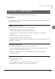
Chapter 1 Product Overview Product Overview This chapter describes features and specifications of the product. Features The TM-S1000 is a compact document scanner that integrates functions for processing business documents such as checks.
Franking Cartridge • Can stamp on documents for electronic settlement • Franking depending on reading results is selectable.
Chapter 1 Product Overview Product Configuration There are multi feed models and single feed models depending on the document feeding methods. For the multi feed models, a 30 dpm model, a 60 dpm model, and a 90 dpm model are available depending on the document processing speeds. For the single feed models, a one pocket model and a two pocket model are available depending on the number of pockets they have, into which documents are ejected.
Accessories Attachments • External power supply (Model: AC adapter. C) • Power switch cover • USB cable (length: 170 cm [66.
Chapter 1 Product Overview Part Names and Functions For Multi Feed Models Auto sheet feeder (ASF) Main pocket Document scanner Sub pocket 1 Scanner cover Scanner cover open lever Pocket guide ASF guide For Single Feed Models Sheet feeder (SF) Main pocket Document scanner Sub pocket* Scanner cover Scanner cover open lever Pocket guide SF guide * The one pocket model does not have a Sub pocket.
For All Models LED indicators Franker cover Franker cover open lever Power switch cover Power switch Power Switch Turns the scanner on or off. Before turning on the scanner, be sure to check that the AC adapter is connected to the power supply. CAUTION Power Switch Cover Install the power switch cover that comes with the TM-S1000 onto the scanner to prevent inadvertent changing of the power switch, to prevent tampering, and to improve the appearance of the scanner.
Chapter 1 Product Overview LED Indicators POWER LED ERROR LED DOCUMENT LED 1 POWER LED (Green) • Lights when the power supply is on. • Goes out when the power supply is turned off. ERROR LED (Orange) Lights or flashes when the scanner is offline. • Lights after the power is turned on or after a reset (offline). Automatically goes out when the scanner is ready. • Flashes when an error occurs or when waiting for document removal. (For details about the flash codes, see "Error Status" on page 27.
DOCUMENT LED (Green) • Lights when the scanner is ready to process documents in the ASF/SF or while the scanner is processing documents. • Flashes when the scanner is waiting for document insertion. When waiting for document removal, the ERROR LED flashes as shown below. Approx.160 ms Approx.160 ms • Out except for the cases above. Connectors All cables are connected to the connector panel on the lower rear of the scanner.
Chapter 1 Product Overview Processing Modes The TM-S1000 has multiple processing modes that are selectable in accordance with how you want to use the scanner. For detailed information about processing modes, see the TM-S1000 API Reference Guide. Multi feed models Processing mode Description High-speed mode The scanner processes a document without stopping from feeding a document until ejecting it.
Processing speed The processing speed (dpm: the number of documents that can be processed in 1 minute) for the multi feed models when using the driver differ depending on the following conditions.
Chapter 1 Product Overview For 60 Dpm Model Paper size Personal check High-speed mode Business check Confirmation mode with overlap Any check Confirmation mode w/o overlap Any check Driver/Application settings*1 Franking/Eject process setting All disabled Regardless One or more enabled Both disabled Processing speed 60 dpm Either or both enabled 32 dpm All disabled Regardless 60 dpm One or more enabled Both disabled Either or both enabled 32 dpm All disabled Regardless 40 dpm*2 One
For 90 Dpm Model Paper size Personal check High-speed mode Business check Confirmation mode with overlap Any check Confirmation mode w/o overlap Any check Driver/Application settings*1 Franking/Eject process setting All disabled Regardless One or more enabled Both disabled Processing speed 90 dpm Either or both enabled 32 dpm All disabled Regardless 75 dpm One or more enabled Both disabled Either or both enabled 32 dpm All disabled Regardless 40 dpm*2 One or more enabled Regardless
Chapter 1 Product Overview Reading Operation The reading operation for the single feed models when using the driver differs depending on the following conditions.
Selectable processes The following processes can be set with the application for both the multi feed models and single feed models.
Chapter 1 Product Overview Sensors There are 7 paper sensors, 2 cover open sensors, and 5 other sensors. Some scanners are not equipped with some of them depending on the model. F I L KJ E D G M N C B A 1 H Paper feed direction Note: The illustration shows the multi feed model. Paper Sensors ASF/SF sensor (A) This sensor is located in the feeder paper path. It detects when a document is in the ASF/SF. When the sensor detects a document, the DOCUMENT LED lights if scanning is possible.
Eject sensor (E) This sensor is located in the feeder paper path. It detects whether a document is properly ejected and stored in a pocket. Main pocket nearly full sensor (F) This sensor is located in the Main pocket. It detects whether documents stored in the pocket need to be removed. • The sensor detects the nearly full status when the thickness of the documents in the Main pocket exceeds the specified value (80 or more of documents whose thickness is 0.13 mm without folds, wrinkles, or roughness).
Chapter 1 Product Overview Other Sensors Franking cartridge sensor (J) This sensor detects whether the franking cartridge is installed or not. Franking cartridge position sensor (K) The franking cartridge is installed in the franking cartridge holder, and the franking operation is achieved by a motor driving the cartridge holder. The scanner has a franking cartridge sensor for detecting the position of the cartridge holder.
Maintenance Counter The TM-S1000 has the maintenance counter to get the following counts.
Chapter 1 Product Overview Error Status There are two possible error types: recoverable errors and unrecoverable errors. Recoverable Errors Processing is no longer possible when recoverable errors occur. They can be recovered easily by turning the power off and then on again or sending an error recovery command from the driver after eliminating the cause of the error. Error LED flash code Error Error description Approx.320 ms Recovery measure Approx.
Error LED flash code Error Error description Approx.320 ms Recovery measure Approx.5120ms Paper jam error • After initialization, paper detected before the CIS. Remove the paper and call BiCancelError of the TM-S1000 API or turn off/on the power. • Paper jam. (Paper length sensor, middle sensor, franking sensor, or ejection sensors detected paper feed error.) Remove the jammed paper and call BiCancelError of the TM-S1000 API or turn off/on the power. • ASF/SF failed in feeding paper.
Chapter 1 Product Overview Unrecoverable Errors Processing is no longer possible when unrecoverable errors occur. The scanner must be repaired. Turn off the power immediately when unrecoverable errors occur. CAUTION Error LED flash code Error Error description Approx.320 ms Approx.5120ms Memory R/W error After R/W checking, the scanner does not work correctly. High voltage error The power supply voltage is extremely high. Low voltage error The power supply voltage is extremely low.
Product Specifications Processing speed (only for the multi feed models) 30 dpm, 60 dpm, or 90 dpm depending on the model. Operating environment CPU 30/60 dpm models without using IQA or single feed models: At least a Pentium 4, 1.2 GHz or the equivalent Multi feed models using IQA or 90 dpm model without using IQA: At least a Pentium 4, 2.
Chapter 1 Product Overview Pocket storage Main pocket 100 sheets or fewer (when the paper thickness is 0.13 mm or less). However, the total thickness must be 13 mm or less including warps. Sub pocket 50 sheets or fewer (when the paper thickness is 0.13 mm or less). However, the total thickness must be 6.5 mm or less including warps.
Scanner Specifications Image Scanner CIS (Contact Image Sensor) Resolution 200 × 200 dpi, 120 × 120 dpi, 100 × 100 dpi Graduation 256-level gray scale, 2 values (Black and White) Data compression format Gray scale JPEG Black and White CCITT/group 4 Data format Gray scale TIFF, JPEG, BMP, Raster Black and White*1 TIFF*2, BMP Scanning area (W × H) 100* (*fixed) × max. 235 mm {3.94* (*fixed) × max. 9.
Chapter 1 Product Overview Paper Specifications Type Normal paper (single-ply only) Size (H × L) 68 ∼ 120 mm {2.68 ~ 4.72 in} × 120 ∼ 235 mm {4.72 ~ 9.25 in} Thickness 0.075 ∼ 0.2 mm {0.003 ∼ 0.008 in} (single-ply only) Weight 60 ∼ 120 g/m2 {16 ∼ 32 lb} • Make sure that the paper has no curl, folds (especially at the top edges), warps, or wrinkles. Otherwise a paper jam may occur.
• The paper sensors ignore the range indicated in the figure below for the guide holes in fan-folded paper. Diameter: 6 mm or less Scannable Area Image scanning may not be possible in the area a, b, and c in the figures below. Image length: Max.269.5 No. 12345 pay to the order of $ Image height: Max.102.6 Dollars c=3.0 MICR character Paper inserting direction b=10.0 a=10.0 Image length: Max.269.5 Image height: Max.102.6 c=3.0 Paper inserting direction b=10.0 34 a=10.
Chapter 1 Product Overview MICR Readable Area MICR readable paper length: Max.235 (10.0) MICR readable length: Max.225 (222.25 [maximum length of check paper] + 2.75) Max. 8.0 Max. 12.25 [Units: mm] 1 Area for Electric Endorsement 120 ~ 235 68~ 100 [Units: mm] Area for Franking 76 25 7.7 25.
Electrical Characteristics Power supply AC adapter, C Operating voltage 24 V ± 10% Current consumption Operating Mean: Approximately 1.0A Standby Mean: Approximately 0.2A Environmental Conditions Temperature/ humidity Operating 10 ~ 40°C {50 ~ 104°F}, 20 ~ 80% RH without condensation (See the operating temperature and humidity range below.
Chapter 1 Product Overview External Dimensions and Mass Height Approximately 176 mm {6.93 in} Width Approximately 355 mm {13.98 in} Depth Approximately 160 mm {6.30 in} 1 Mass Multi feed models: Approximately 4.0 kg {8.82 lb} Single feed models: Approximately 3.9 kg {8.60 lb} 176 160 355 [Unit: mm] Note: The illustrations show the multi feed model.
Chapter 2 Setup Setup This chapter describes setup and installation of the product. Flow of Setup This chapter consists of the following sections along with the setup flow of the product. 1. Installing the Scanner (page 39) 2. Connecting the Scanner to the Host Computer (page 40) 2 3. Connecting the Power Supply Unit (page 41) Do not change the settings of the DIP switch under the bottom cover. Installing the Scanner You can install this scanner only horizontally.
Connecting the Scanner to the Host Computer Connect the scanner to a host computer via a USB port. 1 Start the TM-S1000 Utility included on the Utility & Documents CD. Starting the TM-S1000 Utility causes the USB driver to be installed. Be sure to start the TM-S1000 Utility before connecting the scanner to a host computer. If the scanner is connected to a host computer before installing the USB driver, the Found New Hardware Wizard will be displayed.
Chapter 2 Setup Connecting the Power Supply Unit Use the AC adapter. C as the power supply unit. WARNING 1 2 • Always use the AC adapter. C as the power supply unit. Using a nonstandard power supply can result in electric shock and fire. • Should a fault ever occur in the Epson AC adapter. C, immediately turn off the power to the scanner and remove the power supply cable from the wall socket.
Chapter 3 Application Development Information Application Development Information This chapter gives information useful for scanner application development. Software and Manuals The following software and manuals are provided for application development. Software TM-S1000 API TM-S1000 Utility Description Manual This API controls various functions of the TM-S1000. Log files of API used by applications are helpful for troubleshooting. A silent installation is also available.
TM-S1000 Utility The TM-S1000 Utility is provided for analyzing the scanner and troubleshooting. With the TM-S1000 Utility, you can check the operation of the scanner, confirm the scanner status, and perform MICR cleaning. For more information about the TM-S1000 Utility, see the TM-S1000 Utility User’s manual. Functions of the Utility You can use the following functions by running the TM-S1000 Utility.
Chapter 1 Handling Handling This chapter describes basic handling of the scanner. Turning On/Off Press the power switch to turn the scanner on or off. Power switch 4 Power switch cover If the power switch cover is attached over the power switch, insert a pointed object into one of the holes of the cover to press the switch.
Opening the Covers Do not open the covers during processing. Otherwise a scanning error, a MICR error, or a paper jam may result. Opening the Scanner Cover Pull the scanner cover open lever to open the scanner cover. Open the scanner cover when you clean the glass of the scanner (See "Cleaning the Image Scanner" on page 55.) or remove jammed paper. (See "Removing a Paper Jam" on page 57.) Do not touch the glass areas of the scanner inside the scanner cover with your bare hands.
Chapter 1 Handling Opening the Franker Cover Pull the franker cover open lever to open the franker lever. Open the franker cover when you replace the franking cartridge with new one (See "Installing and Replacing the Franking Cartridge" on page 48.) or remove jammed paper. (See "Removing a Paper Jam" on page 57.
Franking Cartridge Important Notes on the Franking Cartridge • Keep the franking cartridges out of the reach of children. • Do not disassemble franking cartridges. • Be careful during handling because the ink can permanently stain clothing. • Seiko Epson recommends using genuine Epson cartridges for your scanner. Products of other manufacturers may adversely affect the scanner and printing quality, and may result in the scanner not being able to achieve the specified performance levels.
Chapter 1 Handling 3 4 Carefully insert a new franking cartridge from the top, and push it firmly but gently until it clicks in place. Close the franker cover firmly until it clicks in place.
Pulling Out the Guides Pocket guide ASF/SF guide Pocket Guide Be sure to pull out the pocket guide far enough to accommodate the documents stored in the guide before using the scanner. Otherwise a paper jam may occur. ASF/SF Guide Feeding paper using the ASF/SF guide allows you to insert documents straight. Pull out the ASF/SF guide if necessary.
Chapter 1 Handling Processing Documents The TM-S1000 is capable of performing the following four actions on a document in a single pass: scanning the image of both the face and the back, reading magnetic characters, and franking. Flow of Single Pass Processing 4 2 5 3 1 1 Insert a document into the feeder section. (See "Inserting Checks" on page 52.) 2 The scanner scans the images of the face and back. 3 The scanner reads the magnetic characters on the document.
Inserting Checks For the multi feed models, you can put up to 100 documents in the ASF to be fed automatically. For the single feed models, put documents in the SF one by one to be fed automatically. For multi feed models 1 Align the documents neatly on the bottom-right corner as shown in the picture below so that they will be fed one by one. If the documents are inserted without being aligned, they may not be fed at all, or a paper jam or incorrect feeding of multiple documents may result.
Chapter 1 Handling For single feed models 1 Insert a document straight with its face (the side on which magnetic characters are printed) facing outside into the SF, as shown in the picture below. • Do not put more than one document in the SF. Otherwise, a paper jam or incorrect feeding of multiple documents may result. • Be sure to let go of the document before the scanner starts feeding. Otherwise, there may be a paper skew, paper jam, or MICR reading error.
Ejecting Checks When the documents are ejected, remove the documents. Do not leave more than the specified number of documents in the pockets while processing documents (Main pocket: 100 sheets, sub pocket: 50 sheets). Otherwise, a paper jam may occur. Sub pocket Main pocket • Some documents may be ejected into the sub pocket depending on your application. (Except for the one pocket model) • Buzzer may sound to notify errors depending on your application.
Chapter 1 Handling Cleaning Cleaning the Image Scanner If the glass of the scanner gets soiled from ink or paper dust, the quality of the image data may deteriorate. Clean the glass every 6 months or every 100,000 passes. Follow these steps to clean the glass. 1 2 Open the scanner cover. (See "Opening the Scanner Cover" on page 46.) Lightly wipe the glass areas shown in the picture below with a soft, dry cloth.
Cleaning the MICR Unit Dirt on the MICR unit may cause frequent magnetic character reading errors. Clean the MICR unit every 6 months or every 100,000 passes. Use the self-test tool in the CD-ROM included with the scanner or your application to clean the MICR unit. Use KIC Products "Waffletechnology cleaning card (Part No. KW2663-CS1B15WS EPSON CAPTURE ONE WAFFLE WS CLEANING CARDS 15/BOX)." CAUTION • Do not use sticky cleaning sheets. They may cause a paper jam or machine failure.
Chapter 1 Handling Removing a Paper Jam Open the scanner cover or franker cover to remove the jammed paper. (See "Opening the Scanner Cover" on page 46 and "Opening the Franker Cover" on page 47.) Preparing for Transport Follow the steps below to transport the scanner. 1 Turn off the scanner. 2 Confirm that 3 Remove the power supply connector. 4 Store the pocket guide and the ASF/SF guide inside the scanner. 5 Pack the scanner upright. POWER LED is off.