THERMAL LINE PRINTER TM-T60/T60P TM-T80/T80P Operator’s Manual 400206500
All rights reserved. No part of this publication may be reproduced, stored in a retrieval system, or transmitted in any form or by any means, mechanical, photocopying, recording, or otherwise. without the prior written permission of Seiko Epson Corporation. No patent liability is assumed with respect to the use of the information contained herein. While every precaution has been taken in the preparation of this book, Seiko Epson Corporation assumes no responsibility for errors or omissions.
FCC-CLASS A FCC COMPLIANCE STATEMENT FOR AMERICAN USERS This equipment has been tested and found to comply with the limits for a Class A digital device, pursuant to Part 15 of the FCC Rules. These limits are designed to provide reasonable protection against harmful interference when the equipment is operated in a commercial environment.
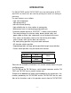
INTRODUCTION The TM-T6O/T6OP and the TM-T8O/T8OP are a one-station printer for ECR and POS use which can be used for printing the results of scaling or measuring. The main features are as follows: . Light and ultracompact . High-speed printing . low-noise thermal printing . High reliability due to a low number of moving parts . Maintenance such as head cleaning performed easily Command protocol based on ESC/POSTM, a widely used standard .
About this manual I . SETTING UP] * Chapter 1 contains information on unpacking the printer, choosing the place for the printer, and names and functions of parts. * Chapter 2 and Chapter 3 contain information on connecting and setting up the printer. * Chapter 4 contains information on testing the printer. II . REFERENCE1 * Chapter 5 contains information on using the printer. * Chapter 6 contains information on software control including printer command descriptions.
II. REFERENCE1 Chapter 5 Cautions while Using the Printer Panel Switches and Commands ............................................. 5 - 2 Printable Area ..................................................................... 5 - 3 Miscellaneous Notes ............................................................ 5-4 Error Correction .................................................................. 5-5 Cleaning the Head ...............................................................
I.
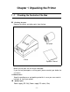
Chapter 1 Unpacking the Printer 1-1 n Checking the Contents of the Box Checking the parts Remove the printer and other parts from the box. l l Roll paper l Operator’s Manual Printer Make sure no parts are missing or damaged. If you find any damaged or missing parts, please contact your dealer for assistance. H Maintenance Keep the packing case and packing materials in case you ever need to transport or store your printer. n Optional parts Power supply (PS-130)) Power supply DC cable (1.
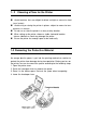
1 - 2 Choosing a Place for the Printer n n n n n Avoid locations that are subject to direct sunlight or excessive heat (near heaters). Avoid using or storing the printer in places subject to excessive temperatures or moisture. Do not use or store the printer in a dusty or dirty location. When setting up the printer, choose a stable, horizontal location. Intense vibration or shock may damage the printer. Ensure the printer has enough space to be used easily.
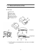
1 - 4 Names and Functions of Parts n Part names Printer cover Operation panel Power connector Interface connector Drawer-kick connector DIP switches (*1) TM-T60/T80 TM-T60P/T8OP * 1: The DIP switches are located behind the small cover on the bottom of the printer.
Operation panel Panel switches POWER Press the POWER button to turn the printer ON and OFF. When the button is pushed down, the power is on. When pressed again, the button returns to its original position, turning the power off. Do not turn the power off during printing. l PAPER FEED l Press the PAPER FEED button to feed roll paper. You cannot feed paper when the printer cover is open. Panel lights (LED) POWER (green) The POWER light is on when power is turned on.
Chapter 2 Before Setting Up 2- 1 Connecting the Power Supply to the Printer n Plugging in AC adapter The printer must be connected to an external power supply. Be sure to use a power cable that matches the specifications of both the printer and the power supply unit. --------------------------------------------------------------------CAUTIONS: Before connecting the printer to the power supply, make sure that the voltage (24 VDC) and power specifications match the printer’s requirements.
2-2 Connecting the Host Computer to the Printer n Connecting the interface cable Connect the printer to a host ECR (host computer) using an interface cable matching the specifications of the printer and the host ECR (host computer). TM-T6O/T80 Connect the interface cable according to the following procedure. Turn off the printer, power unit, and host computer.
TM-T60P/T80P Connect the interface cable according to the following procedure. Turn off the printer, power unit, and host computer. Plug the interface cable connector into the interface connector on the printer. Squeeze the wire clips together until they lock in place on both sides of the connector. Attack the ground wire to the ground connector on the right side of the interface connector.
Chapter 3 Installing the Parts 3-l Installing the Roll Paper Installing the roll paper Be sure to use roll paper that matches the printers specifications. Using scissors, cut the leading edge of the roll paper perpendicular to the paper feed direction. Open the printer cover and raise the release-lever toward you. Release lever Load the roll paper while Iightiy pressing the right roll paper holder outward. Release the holder after fitting the paper core onto the holder.
Chapter 3 Installing the Parts 3-l Installing the Roll Paper Installing the roll paper Be sure to use roll paper that matches the printers specifications. Using scissors, cut the leading edge of the roll paper perpendicular to the paper feed direction. Open the printer cover and raise the release-lever toward you. Release lever Load the roll paper while Iightly pressing the right roll paper holder outward. Release the holder after fitting the paper core onto the holder.
Insert the edge of the roll paper into the paper slot and turn the paper-feed knob in the direction of the arrow to feed the paper 5 cm beyond the tear-off edge. Don’t turn the paper-feed knob when the release lever is down. l Paper-feed knob Raise the head-open lever, unroll the paper a little and pull lightly from the roll paper side to eliminate twist or misalignment. Retighten the roll paper to remove any slack. Roth edges of the paper should be aligned parallel to the paper roll.
n Removing jammed paper Removing jammed paper according to the following steps. Open the printer cover and raise the head-open lever. r I _ _ _ - - - _ _ _ - - _ _ _ - - - - - - - - - - - - - - - - - - - - - - - - - - - - - - - - - - - - - - - - - - - - - - - - - - - - - - - - - - - - . CAUTION: * The print head is very hot immediately after printing. Always remove jammed paper after the print head has cooled. I I I I Head-open lever r Remove any jammed paper.
3 -2 Adjusting the Paper-End Detector n The paper-end detector The paper-end detector senses when the paper is nearing its end and turns on the PAPER lamp. The paper-end detector can be adjusted according the thickness of the Paper. n How to adjust the paper-end detector Roll paper may differ in spool size, so it may be necessary to adjust the paper-end detector. Use the specified paper roll with a cure inside diameter (d1) of 12mm and an outside diameter (d2) of 18 mm.
Loosen the adjusting screw that holds the paper-end detector. Then set the top of the positioning plate to the appropriate adjustment position, and tighten the adjusting screw. NOTES: 1 . The T dimensions corresponding to the adjustment values in II the table are caluculated from standard measurements; some II variations in the actual mechanism. I 2. After adjusting, ensure that the detector operates smoothly.
3 -3 Setting the DIP Switches n Locating the DIP switches On the underside of your printer are a number of DIP switches that can be set to perform a number of different functions. - You can change the function of your printer by turning DIP switches on or off. - Current DIP-switch settings are printed out during the self test. - The switches numbered from left to right are SW1-1 through SW1-10 (TM-T6O/T80) or SW1-1 through SW1-5 (TM-T6O/T80P).
n TM-T60/T60 DIP-Switch Functions Table 3-2 DIP-Switch Functions (On the bottom of the case) DIP SW1 SW- 1 ON OFF Ignores data reception errors Prints “?” for data reception errors - - - - - - - - - - - - - - - - - - ---------------------.
n TM-T60P/T80P DIP-Switch Functions Table 3-5.
Chapter 4 The Self Test 4 - 1 The Open-Cover Detector n The open-cover detector This unit has an open-cover detector located inside the printer cover. - Data is not printed when the printer cover is open. - Opening the cover sets the printer OFF LINE; data cannot be received when the printer is OFF LINE. - Paper cannot be fed with the paper-feed switch when the printer cover is open. n Returning the printer ON LINE - Closing the cover sets the printer ON LINE automatically.
4 -2 Checking Operation with the Self Test n The purpose of the self test The self test checks whether the printer has any problems. When the printer does not function properly, please contact the dealer. n The self test checks the following - Control circuit functions - Printer mechanism - Print quality n - Control ROM version .
II.
Chapter 5 Cautions while Using the Printer 5-l Panel Switches and Commands n switches J (1) Power switch Function t I I Note Turns the power supply on/off. The RAM is initialized after turning off the circuit power supply. Don’t touch the power supply switch during printing. (2) Paper-Feed switch Function If this switch is pressed, paper is fed one line based on the currently specified line spacing.
5-2 Printable Area n Printable Area The print area must be within the range indicated below.
5 -3 Miscellaneous Notes n Notes on printing and paper feeding (1) Because the TM-T60/T8OP and TM-T8O/T8OP are a line printer, they automatically feed paper after printing the data. When the line spacing is set to a small value, the paper may be fed mare than the set amount to print all the data.
(2) When the printer goes to the standby (data-waiting) state during printing, the printer stops printing and feeding paper temporarily. When the printer restarts, the paper may shift 1 to 3 dots at the start of printing. Graphics printing is particularly affected by this. n Notes on the power supply • Turn the external power supply on after connecting it to the power supply connector. • Be sure you don’t connect the external power supply with the wrong polarity.
n Handling thermal paper (1) Notes on using thermal paper Chemicals and oil that come into contact with the thermal paper may cause paper discoloration, and can also cause the ‘printing to fade. Therefore, pay attention to the following: a) Use water-based paste, starch paste, polyvinyl paste, or MC paste when gluing thermal paper. b) Volatile organic solvents such as alcohol, ester, and ketone can cause discoloration.
5-4 n Error Correction ERROR LED (red) Lights: On when the printer cover is not closed completely, or when the paper roll is near the end. Blinking: Blinks during the error states shown in Table 5-3. Blinks during the print-waiting state (macro executing command) shown in Table 5-4. Table 5-3.
Table 5-3. Error Display (Continued) Error Print head thermistor error Internal data processing error 150 ms 150 ms Print head overheating error 900 ms 300 ms Impossible to recover 150 ms 150 ms 150 ms Print head paper out error Recovery ON/OFF Timing Pattern Recovered by turning the power off and on 1950 ms 150 ms 150 ms --150 ms 150 ms Recovered by closing the cover after inserting paper 1650 ms Recovers automatically when the print head temperature drops back down 1350 mS Table 54.
5-5 Cleaning the Head n Cleaning the head Cleaning the head according to the following procedure. I I CAUTION: Do not clean the head immediately after printing; the head may be hot. I ---------------------------------------------------------------------------Œ Open the printer cover and raise the head-open lever. If roll paper is loaded, remove it from the head area. • Clean the heating element of the head with a cotton swab containing an alcohol solvent (ethanol, methanol, or IPA).
Chapter 6 Software Control 6 - 1 Printer Control n Controlling the printer with commands The printer is controlled by “commands” that can change the size of the characters, and perform other functions. See APPENDIX E Character Code Tables and APPENDIX F command Summary. There are two types of commands.
6 - 2 Command Descriptions n Command descriptions *XXX * N a m e * F o r m a t Command The name of the command The code sequence In this description, < >H denotes hexadecimal numbers, < > denotes decimal numbers and < >B denotes binary numbers. [ ]k indicates the contents of the [ ] should be repeated times.
6 - 3 Commands HT Horizontal tab < 09 > H Moves the print position to the next horizontal tab position. . This command is ignored unless the next horizontal tab position has been set. - Horizontal tab positions are set using ESC D. - The default horizontal tab positions are at intervals of 8 characters (9th column, 17th, 25th. . .) for Font A. ESC D LF Print and line feed Prints the data in the print buffer and performs 1 line feed based on the current line spacing.
ESC SP n Set character right-side spacing < 1B > H < 20 > H < n > Sets the character right-side spacing in dot units ( l/180inch units). • The character right-side spacing for double-width mode is twice the set value. n=O ESC ! n Set print mode < 1B >H < 21 >H < n > Sets a print mode. • Each bit of n is used as follows: Value Bit Function 1 0 Font A Font B 0 Character font ----~-------------------------------..
Sets or cancels the user-defined character set. • Only the lowest bit of n is valid. When n = < * * * * * * * 1 > B , the userdefined character set is set. W h e n n = < * * * * * * * O >B , the u s e r d e f i n e d c h a r a c t e r set is canceled (and the internal character set is set). n = 0 ESC & ESC & s n m [a[p]sXa]m-n+1 Define user-defined characters < 1 B >H < 2 6 >H < s > < n > < m > [ < a > < p 1 > < p2 >---< psXa >] m-n+1 s=3 Defines user-defined characters for ANK character codes.
executed, until GS * is executed, or until the printer is turned off. .
ESC * m n1 n2 [d]k Set bit image mode < 1B >H < 2A >H < m >< n1 >< n2 >[< d >]k k = n1 + 256 X n2 (m= 0, 1) k = (n1 + 256 x n2) X 3 (m = 32, 33) Sets the bit image mode using m and the number of dots using n1 and n2. Divide the number of dots to be printed by 256. The integer answer is n2 and the remainder is n1. Therefore, the number of dots in the horizontal direction is: n1+256Xn2. . If the bit image data input exceeds the number of dots to be printed on a line, the excess data is ignored. .
. The relationship between the image data and dots to be printed is as follows: - 8-dot bit image - 24-dot bit image -35-
ESC 2 Set 1/6 inch line spacing < 1B >H < 32 >H Sets the line spacing to 1/6 of an inch. ESC 3 n Set line spacing using minimum units < 1B >H < 33 >H < n > Sets the line spacing to n/360 of an inch. n = 60 (1/6 inch) 5-3 Miscellaneous Notes ESC @ Initialize printer < 1B >H < 40 >H Clears the data in the print buffer and resets the printer mode (to the same state as when the power is turned on). - The DIP switches are not read again. The data in the receive buffer is not cleared.
- A horizontal tab position is stored as the absolute value of (character width X n) measured from the beginning of the line. The character width includes the character rightside spacing, and double-width characters should be set with twice the width of normal characters. - Up to 32 tab positions can be set. Data which exceeds 32 tab positions will be ignored. - Set k in ascending order and place a NUL code <00>H at the end. - ESC D NUL clears all tabs.
ESC R n Select international character set n selects an international character set from the following table. n 0 1 2 3 4 5 Country U.S.A. France Germany U.K. Denmark I Sweden Country n 6 7 8 9 10 Italy Spain Japan Norway Denmark II n = 0 APPENDIX E Character Code Tables ESC c3 n Select paper detectors to output signals < 1B >H < 63 >H < 33 >H < n > This function is available only for the TM-T60P/T80P. Select the paper detectors to output signals on the “paperend status line”.
- In the TM-T60P/T80P, only the journal near-end detector can be detected and only the lowest of n is valid. n = 1 ESC c4 n Select paper detectors to stop printing < 1B >H < 63 >H < 34 >H < n> Selects the paper detectors used to stop printing.
When n = < * * * * * * * 0 > 8 , the paper feed switch is enabled. When n = < * * * * * * * 1 > 8 , the paper feed switch is disabled. - If the panel switches are disabled by this command, the paper feed switch is disabled. Therefore, paper cannot be fed with the paper feed switch. n = 0 ESC d n Print and feed paper n lines < 1B >H < 64 >H < n > Prints the data in the print buffer and performs n line feeds. - Sets the print starting position to the beginning of the line.
ESC t n Select character code table < 1B >H < 74 >H < n > Selects page n from the character code table. n = 0 APPENDIX E Character Code Tables ESC v Transmit printer status < 1B >H < 76 >H This function is available only for the TM-T60/T80. The current printer status is transmitted to the host computer. - The transmitted status is only one byte and the data is as shown in the following table. .
ESC u n Transmit peripheral device status < 1B >H < 75 >H < n > n = 0 This function is available only for the TM-T60/T80. Transmits the status current of connector pin 3. - n is specified as follows: n Connector Pin 0 Drawer-kick connector Pin 3 . The transmitted status is only one byte and the data is as shown in the following table. - lf nothing is connected, bit 0 of n is always "1". .
Sets or cancels upside-down character printing. - Only the lowest bit of n is valid. When n = <*******1> B , upside-down character printing is set. When n = <*******0> B , upside-down character printing is canceled. - The upside-down character specification rotates normal characters on the line by 180° and prints them. - Valid only when input at the beginning of a line. n = 0 When upside-down character printing is canceled. When upsidedown character printing is set.
Sets the print starting position to the specified number of dots (1/180 inch units) from the beginning of the line. - Divide the number of dots by 256. The integer answer is n2 and the remainder is n1. Therefore, the print starting position becomes n1+n2X256 from the beginning of the line. - Any specification that exceeds the end of the line is ignored. Not defined.
- “d” indicates the characters to be printed and “k" indicates the number of characters to be printed. n 0 1 2 3 4 5 6 Bar code system UPC-A IPC-E JAN13(EAN) JAN8(EAN) CODE39 ITF CODABAR . When data is present in the print buffer, this command is ignored. - Performs the paper feeding required for printing the bar code, regardless of the current line spacing. .
GS h n Select height of bar code < 1D >H < 68 >H < n > Selects the height of the bar code. - n specifies the number of dots in the vertical direction. n = 162 GS H n Select printing position of HRI characters < 1D >H < 48 >H < n > Selects the printing position of HRI characters when printing abarcode. - n selects the printing position from the following table.
- n selects the font from the following table. n Font 0 Font A 1 Font B . HRI means Human Readable Interpretation. - HRI characters are printed at the position specified by GS H. n = 0 GS H GS * n1 n2 [d]n1Xn2X8 Define down-loaded bit image < 1D >H < 2A >H < n1 >< n2 >[< d >]n1Xn2X8 Defines a down-loaded bit image with the number of dots specified by n1 and n2. - The number of dots in the horizontal direction is n1X8, and in the vertical direction is n2X8. - “d" specifies the bit image data.
GS / m Print down-loaded bit image < 1D >H < 2F >H < m > Prints a down-loaded bit image using the mode specified by m. - m selects the print mode from the following table. Vertical Direction Dot Density 0 Normal mode 180 DPI 1 Double-width mode 180 DPI 2 Double-height mode 90 DPI Mode m 3 90 DPI Quadruple mode Horizontal Direction Dot Density 180 DPI 90 DPI 180 DPI 90 DPI If any data is present in the print buffer, this command is ignored.
GS : Set starting/ending, position of macro definition < 1D >H < 3A >H Specifies the starting or ending position of the macro definition. - If this command is received while defining the macro, it ends the definition. - If the macro range exceeds 2048 bytes, the excess data is not defined. - Even if the ESC @ command (initialize the printer) is performed, the macro definition is not cleared. Therefore, it possible to include ESC @ in the macro definition.
waits for the paper feed switch to be pressed. After the paper feed switch is pressed, the printer executes the macro once. The printer repeats this operation n1 times. • If this command is received while defining the macro, the macro definition is aborted, and the definition is cleared. • If the macro is not defined or if n1 is 0, nothing is executed. • Paper cannot be fed with the paper feed switch while executing the macro when n3 is 1. Not defined.
ESC a n Name Format Range Description Align positions < 1B > 0 n H < 61 > H < n > 2 Aligns all the data in one line to the specified position. n specifies the alignment as follows: • Notes Default Example Align left ABC ABCD ABCDE • Valid only when input at the beginning of a line.
6 - 4 Program Descriptions TM-T60/T80 1. Introduction The TM-T6O/T80 is connected to the host computer by an RS-232C interface. The TM-T60/T80 is easily controlled by sending data and commands from the host computer. The following examples use the main commands from MS-DOS BASIC. 2. Before Printing Connect TM-T60/T80m to the host computer, power supply, and the drawer while referring to Chapter 2. Check that the RS-232C cable is connected properly, and the host computer DIP-switches are set properly.
In order to execute ESC @ (Initialize the printer) send “@" following the ESC code. Always write ” ; ” at the end of the commands or BASIC will send a CR and LF code. Sending Print Data 120 PRINT #1, “ABCDEF” ;CHR$(1O); Always send a LF code (CHR$ (10)) after print data. To execute printing, send a LF code or ensure the line is filled.
Selecting character Font A and Double-width 150 PRINT #1, CHR$(27); ”!” ;CHR$(48); 160 PRINT #1, ”ABCDEFGHIJK” ;CHR$(10); TM-T60 Font A (normal) Font A (double-width) : 32 characters per line. : 16 characters per line. Resetting the style to Normal. 170 PRINT #1, CHR$(27); ”!” ;CHR$(O); 180 PRINT #l, ”ABCDEFGHIJK” ;CHR$(10); 170 sets Font A to Normal. 180 sets the characters for printing.
Selecting international character codes 280 PRINT #1, CHR$(91);CHR$(92);CHR$(93);CHR$(94);CHR$(l0); 290 PRINT #1, CHR$(27); "R" ;CHR$(1); 300 PRINT #1, CHR$(91);CHR$(92);CHR$(93);CHR$(94);CHR$(l0); 280 prints 4 U. S. A characters. (default) 300 prints 4 French characters. Refer to ESC R n Resetting Printer functions 310 PRINT #1, CHR$(27); "@"; Initialize printer again.
Using the drawer kick 350 PRINT #1, CHR$(27);"p";CHR$(O);CHR$(10);CHR$(100); The “p” generates a specified pulse; Refer to ESC p m n1 n2. In line 350, the module terminal of the drawer kick outputs a 20-ms pulse followed by a 200-ms wait. How to read the status of the drawer kick 360 370 380 390 PRINT #1, CHR$(27);"u";CHR$(O); A$=INPUT$(1, #1) IF A$=CHR$(0) THEN PRINT "DRW:L" IF A$=CHR$(1) THEN PRINT "DRW:H" The “u” command in line 360 transmits the status of the drawer kick to printer.
* * * * * * * * Program List ******** in MS-DOS BASIC HOST COMPUTER:EPSON PC-286 100 OPEN "COM1:N81NN" AS #1 110 PRINT #1,CHR$(27);"@"; 120 PRINT #1,"ABCDEF";CHR$(10); 130 PRINT #1,CHR$(27);"!";CHR$(1); 140 PRINT #1,"ABCDEF";CHR$(10); 150 PRINT #1,CHR$(27);"!";CHR$(48); 160 PRINT #1,"ABCDEFGHIJK";CHR$(10); 170 PRINT #1,CHR$(27);"!";CHR$(O); 180 PRINT #1,"ABCDEFGHIJK";CHR$(10); 190 FOR I=240 TO 255 200 PRINT #1,CHR$(I); 210 NEXT I 220' 230 PRINT #1,CHR$(27);"t";CHR$(1); 240' 250 FOR I=240 TO 255 260 PRINT
n TM-T60P/T80P Except for the different interface connectors accommodated by the two types of the printer TM-T60/T80 and TM-T60/T80P, the description for the TM -T60P/T80P printer is same with the TM-T60/T80’s which are mentioned be fore. However, omit step 12, because the TM-T60P/T80P can know the status of the drawer-kick through pin 34 of the parallel interface connector.
APPENDIX APPENDIX A General Specifications 1. Printing specifications (1) Print method: (2) Dot density: (3) Printing direction: Thermal line printing 180 dpi Unidirectional with friction feed (Manual reverse feeding is impossible) (4) Print width (TM-T60/T60P): 54mm, 384 dot positions (TM-T80/T80P): 72mm,512 dot positions (5) Characters per line(TM-T60/T60P): 32 (Font A) : 42 (Font B) (TM-T80/T80P): 42 (Font A) : 56 (Font B) (6) Character spacing: 0.28 mm (Font A) 0.
(8) Paper feeding speed (TM-T60/T60P): Approx. 2.0 inches/second (Approx. 50.0 mm/second) (TM-T80/T80P): Approx. 1.5 inches/second (Approx. 38.0 mm/second) (9) Line spacing: 1/6 inch (4.23 mm) default Programmable by control command. (Minimum 1/360 inch) 2.
3. Near-end detector (1) Detection method: (2) Roll paper core diameter: (3) Adjustment mechanism: (4) Adjustment units: Microswitch Inside diameter: 12 mm Outside diameter: 18 mm Adjusting screw The near-end detection processing is programmable by control command. Approx. 2 mm/scale division 4. Paper Specified thermal paper (2) Paper thickness: 65±5 µm (3) Form: Roll paper (4) Paper width (TM-T60/T60P):60±° 1 mm (TM-T80/T80P):80±° 1 mm (5) Roll size: Roll diameter: Max.
Standby: Peak: Approx. 6.0 A (Print duty: 100%) Approx . 100mA 7. EMI (by using Epson PS-130) (1) FCC: -Class A (2) FTZ: Class B 8. Reliability MCBF: 3,500,000 lines (Printing Font A characters) 9. Environmental conditions (1) Temperature Operating: Storage: (2) Humidity Operating : Storage: 5 to 40°C -10 to 50°C (except for paper) 30 to 85°C (non-condensing) 30 to 90% (non-condensing, except for paper) 10.
APPENDIX B Connectors 1. Connectors TM-T60/T80 TM-T60P/T80P 2. Interface connectors Refer to APPENDIX C Interfaces 3. Power supply connector This connector is used to connect an external power source. (1) Pin assignment: Pin 1: +24 VDC 2 Pin 2: GND Pin 3: Unconnected SHELL SHELL: Connected to the frame ground (FG) at the printer side.
4. Drawer-kick connector (Modular connector) NOTE: If the drawer-kick connector is covered, the drawer-kick function is not available. (1) Pin assignment: Printer side connector: TM5RJ3-66 (HIROSE) or 1 . . . 6 equivalent User-side plug: Standard 6-pin modular jack (RJ11 Telephone jack) Table B-l. Drawer-kick out Connector Pin Assignment Pin Number Signal Name Sender Connected to: Function 1 FG Frame ground.
(3) Electrical characteristics Maximum -1 A (510 ms or less) (a) Signal output current: (b) Power ‘supply output voltage: 24 VDC (typical) (c) Power supply output current: Maximum 1A (510 ms or less) Refer to Figure B-2. (d) Output waveform: NOTE 1: These are not output during printing. 2: Drawer-kick drive signals L1 and L2 cannot be output at the same time. Drawer open/close signal SW(+) signal level: “LOW = 0 to 0.5 V “HIGH” = 3 to 5 V Printer side User side Figure El.
APPENDIX C Interfaces TM-T60/T80 1. Specifications (RS-232C compatible) Data transmission: Synchronization: Handshaking: Signal level: Baud rates: Bit length: Parity: Stop bits: Connector: Serial Asynchronous DTR/DSR or XON/XOFF control MARK = -3 to -15 VDC: Logic “1” SPACE = +3 to +15 VDC: Logic “0” 1200, 4800, 9600, 19200 bps 8 bits Invalid, even, odd 1 bit or more D-SUB 25 pin connector 2.
3. Serial interface (a) Receive data Either DTR/DSR or XON/XOFF control is selectable. Changes in DTR signal and XON/XOFF transmission are as follows: * The period from when the power is turned [DTR MARK] on to when the printer is first ready to receive data. * In an error state. * When the remanig space in the recive buffer becomes 10 bytes. * When the printer is first ready to receive data after power-on. * When the remaining space in the receive buffer becomes 20 bytes.
2. Interface connector terminal assignments and signal functions Pin Number Signal Name 1 STROBE Function Signal Direction STROBE pulse for reading data. lnput Normally, this signal is “HIGH”. just after it goes “LOW”, the printer reads the data. Pulse width must be 0.5 µs or more at the receive terminal. These signals are ths eight parallel data tits. “HIGH” indicates that the tit is "1" and "LOW" indicates that is "0".
NOTES: 1. For interface wiring, be sure to use a twisted-pair cable for each side and connect the return side to the signal GND level. To prevent noise, these cables should be shielded and con nected to the chassis of the host computer. 2. Ail of the interface conditions are based on TTL levels. The rising time and falling time of any signal should be 0.2 µs or less. 3. Never transmit data without checking ACKNLG and BUSY.
3. Parallel interface timing chart Approx. 5 µs Approx. 5 µ S BUSY ACKNLG I STROBE I I Reception of data is controlled by the ACKNLG or BUSY signal. The BUSY signal gose “HIGH” depending on whether the receive buffer is available or not as follows: • During the period from when power is turned on to when the printer initialization completes. • During the self test printing • During data entry • in the OFF-LINE state • in the receive buffer full state. • in a mechanical error state.
APPENDIX D Notes on Using the Drawer kick-out Connector 1) Usage conditions of drawer kick-out connector (Refer to APPENDIX B). Because drawer specifications differ greatly depending on the manufacture and the part No., make sure that the specifications of the drawer to be used meet the following conditions before connecting it to the drawer kickout connector of this printer. These conditions also apply to any devices that use the drawer kick-out connector.
2) Notes on using the specified pulse generation command (ESC p) When the drawer is connected to the drawer kick-out connector and driven using the specified pulse generation command (ESC P), specify the parameters n1 and n2 in this command so that they will meet the following conditions. ON time ON time + OFF time or OFF time (Formula D-1) 0.2 (Formula D-2) ON timeX4 When the drawer is driven in accordance with the conditions above, the signal waveform of the drive signal is as shown in Figure D-l .
The foIlowing shows an example program used when the drawer connected to the drawer drive signal 1 is driven using an ON time of 200 ms. PRINT #1, CHR$(&H1B);“P”;CHR$(0);CHR$ GOSUB*WAlT3OOMS ON time 200ms *WAlT3OOMS (* NOTE) 300[ms] wait routine RETURN OFF time 500ms NOTE: *This part is indicated in Formula D-3. Set this value so that it can satisfy Formula D-3 (or provides an internal processing time at least as long as the wait routine time.
n International character set -76-
APPENDIX F Command Summary T60/T80 T60P/T80P Command Name Command Horizontal tab O HT O -----------------------------------------------------------------------------------------O LF Print and line feed O ------------------------------------------------------------------------------ N.A.
-78-