TM-T70 Technical reference guide (ANK model) English 410620800 EPSON
TM-T70 Technical Reference Guide Cautions ❏ No part of this document may be reproduced, stored in a retrieval system, or transmitted in any form or by any means, electronic, mechanical, photocopying, recabling, or otherwise, without the prior written permission of Seiko Epson Corporation. ❏ The contents of this document are subject to change without notice. Please contact us for the latest information.
For Safety Key to Symbols The symbols in this manual are identified by their level of importance, as defined below. Read the following carefully before handling the product. WARNING: You must follow warnings carefully to avoid serious bodily injury. CAUTION: Provides information that must be observed to prevent damage to the equipment or loss of data. ❏ Possibility of sustaining physical injuries. ❏ Possibility of causing physical damages. ❏ Possibility of causing information loss.
TM-T70 Technical Reference Guide Warnings WARNING: ❏ Shut down your equipment immediately if it produces smoke, a strange odor, or unusual noise. Continued use may lead to fire or electric shock. Immediately unplug the equipment. ❏ Only disassemble this product as described in this manual. Do not make modifications to the unit. Tampering with this product may result in injury, fire, or electric shock.
Cautions CAUTION: ❏ Be sure to set this equipment on a firm, stable horizontal surface. Product may break or cause injury if it falls. ❏ Do not use in locations subject to high humidity or dust levels. Excessive humidity and dust may cause equipment damage, fire or shock. ❏ Do not place heavy objects on top of this equipment. Never stand or lean on this equipment. Equipment may fall or collapse, causing breakage and possible injury.
TM-T70 Technical Reference Guide Conditions of Acceptability 1. The supply source shall be SELV and non-hazardous energy level (less than 240VA). 2. When this product is installed in the product which has a total mass not exceeding 18kg, the enclosure of this product were evaluated as a fire enclosure. 3. The interface connectors except for input connector shall be described in installation or safety instruction to identify Non-LPS at end product.
About this Manual This manual describes the TM-T70, a current EPSON thermal printer product. The currently available power supply, the PS-180, works with TM-T70. Aim of the Manual This manual was created to provide all the information necessary for system planning, design, installation, and application of the printer for designers and developers of POS system.
TM-T70 Technical Reference Guide Name of document Description EPSON OPOS ADK Manual Provides information for anyone who is programming using OPOS. This is included in the EPSON OPOS ADK.* EPSON Advanced Printer Driver This is a Windows driver.* EPSON Advanced Printer Driver Manual Provides information for anyone who is programming using the APD (EPSON Advanced Printer Driver). This is included in the EPSON Advanced Printer Driver.
viii Rev.
TM-T70 Technical Reference Guide Contents Chapter 1 Product Overview Features . . . . . . . . . . . . . . . . . . . . . . . . . . . . . . . . . . . . . . . . . . . . . . . . . . . . . . . . . . . . . . . . . . . . . . . . . . . . . . . . . . . . . . Product Structure . . . . . . . . . . . . . . . . . . . . . . . . . . . . . . . . . . . . . . . . . . . . . . . . . . . . . . . . . . . . . . . . . . . . . . . . . . . . . . Model . . . . . . . . . . . . . . . . . . . . . . . . . . . . . . . . . . . . . . . . .
NVRAM (Non-volatile Memory) . . . . . . . . . . . . . . . . . . . . . . . . . . . . . . . . . . . . . . . . . . . . . . . . . . . . . . . . . . . . . . . . . 3-11 Bar Code Printing . . . . . . . . . . . . . . . . . . . . . . . . . . . . . . . . . . . . . . . . . . . . . . . . . . . . . . . . . . . . . . . . . . . . . . . . . . . . . . 3-12 Notes on Printing 2-Dimensional Code . . . . . . . . . . . . . . . . . . . . . . . . . . . . . . . . . . . . . . . . . . . . . . . . . . . . . . . . . . . .
TM-T70 Technical Reference Guide Chapter 1 Product Overview The TM-T70 thermal printer product is currently available from EPSON. In addition, the PS-170, the power supply, is obsolete and no longer available. It is described only for legacy support. The currently available power supply, the PS-180, works with TM-T70. 1.1 Features The TM-T70 printer has the following features: ❏ Printing • High-speed printing (170 mm/s {6.69"/s} maximum), which enables issuing of batch receipts.
1.2 Product Structure 1.2.1 Model ❏ Product Name TM-T70 (current product) • Print method: Thermal line printing • Interface specifications: Serial interface specifications (RS-232C) Parallel interface specifications (IEEE 1284-compliant) USB interface specifications (Full speed) Ethernet interface specifications (10/100BASE-T) Wireless LAN interface specifications (802.11b) • Paper width specifications: 80 mm {3.15"} width specifications 1.2.
TM-T70 Technical Reference Guide 1.2.5 TM-T70 Basic Specification Table Table 1-1 TM-T70 1. High-speed print mode Approx. 170 mm/s (6.99") maximum 2. High-speed power consumption mode Average : Approx. 1.8A 3. Serial interface selectable baud rates 2400, 4800, 9600, 19200, 38400, 57600, 115200 Default Setting: 115200 Settable baud rate with DIP switches 1-7/1-8: 4800, 9600, 19200 Settable baud rate with commands: 2400, 4800, 9600, 19200, 38400, 57600,115200 4.
1.3.2 Control Panel TM-T70 FEED button PAPER OUT LED ERROR LED (POWER) LED 1.3.2.1 LED (POWER) LED (green) ❏ Lights when the power supply is on. ❏ Goes out when the power supply is turned off. ERROR LED Lights or flashes when the printer is offline. ❏ Lights after the power is turned on or after a reset (offline). Automatically goes out after a while to indicate that the printer is ready. Lights when the end of the roll paper is detected, and when printing has stopped (offline).
TM-T70 Technical Reference Guide 1.3.3 Power Switch The power switch is located at the bottom right front of the printer. (Refer to “Printer part names” (page 1-3).) Turn the printer on or off. The marks on the switch ( position. / ) indicate the printer switch CAUTION: Before turning on the printer be sure to check that the AC adapter is connected to the power supply. 1.3.4 Connectors All cables are connected to the connector panel on the lower rear of the printer.
1.4.1 Installing and Replacing Roll Paper Note: Be sure to use roll paper that meets printer specifications. See Appendix B for details on the paper specifications. Do not use roll paper whose trailing end is glued to the roll paper core. 1.4.1.1 Installing Roll Paper 1. Check that printing is stopped, and press the cover open button to open the printer cover. Figure 1-3 Cover open button 2. Load the roll paper.
TM-T70 Technical Reference Guide 3. Pull out the roll paper toward you, then set it so that it fits between the left and right paper guides on top of the printer cover. Paper guides Figure 1-6 Pulling out the roll paper 4. Close the printer cover. Figure 1-7 Closing the printer cover 5. Tear off the leading edge of the roll paper. Figure 1-8 Tear off paper Rev.
1.4.1.2 Replacing Paper Follow the procedure below to replace roll paper. 1. Open the printer cover, and remove the core of the previously used roll paper. 2. Insert the new roll paper following the procedure in “Installing Roll Paper” (page 1-6). 1.4.2 Removing Jammed Paper CAUTION: Do not touch the thermal head because it can be very hot after printing. For handling the thermal head, refer to TM-T70 User’s Manual. 1. Turn the printer off and press the cover open lever. 2.
TM-T70 Technical Reference Guide 1.4.4 Shipping Procedures Do the following before shipping the printer. 1. Press the power switch to turn the power off. 2. Make sure the LED is out. 3. Remove the power supply connector. 4. Remove the roll paper. 5. Pack the printer, keeping the top and bottom correctly oriented. Rev.
1-10 Product Overview Rev.
TM-T70 Technical Reference Guide Chapter 2 Setup Before using the printer, you need to make various settings to increase the printer's functionality. Configure the printer appropriately depending on the environment. 1. Install the printer (page 2-1) Detailed setup 2. Set the DIP switches (page 2-3) Note: Detailed setup sometimes can be omitted. 3. Connect the printer to the host computer (page 2-7) 4. Connect the power supply and cash drawer (page 2-14) 5.
Fix the printer so that it does not move around when you open the printer cover and cut roll paper. A tape for fixing the printer is available as an option. As shown in the illustration below, install the printer with a maximum tilt of 3°. Installing the printer with a tilt of more than 3° may cause the following problems. • Roll paper near end cannot be detected. • The printer cover will not close after installing roll paper. • Roll paper cannot be taken out.
TM-T70 Technical Reference Guide 2.2 Setting the DIP Switches On this printer, you can make various settings with DIP switches. Note: Serial interface communication conditions must be set on serial interface model printers. 2.2.1 DIP Switch Positions and Steps for Changing DIP Switch Settings Follow the steps below to change the DIP switch settings. CAUTION: Before you remove the DIP switch cover, turn the printer off. Otherwise, a short-circuit may cause the printer to malfunction. 1.
2.2.2.1 DIP switch settings for serial interface specifications Note: * Factory setting Table 2-2 Dip Switch bank 1 settings SW Function ON OFF DEFAULT 1-1 Data receive error Ignore “?” is printed * OFF 1-2 Receive buffer size 45 bytes 4KB * OFF 1-3 Handshake XON/XOFF DTR/DSR * OFF 1-4 Bit length 7 bits 8 bits * OFF 1-5 Parity check Yes No * OFF 1-6 Parity selection Even Odd * OFF 1-7, 1-8 Baud rate selection (See the “Baud rate selection” tables below.
TM-T70 Technical Reference Guide Table 2-4 Dip Switch bank 2 settings SW Function ON OFF DEFAULT 2-1 Handshake (BUSY) conditions • • OFF Receive buffer full • Offline Receive buffer full* 2-2 Reserved (do not change setting) Fixed to OFF OFF 2-3, 2-4 Print density selection/low-power mode (See separate table.) OFF 2-5 Reserved (Always use printer with these switches to OFF.
Note: * Factory setting Table 2-6 Parallel/USB/Ethernet/Wireless LAN DIP switch bank 1 SW Function ON OFF DEFAULT 1-1 Automatic line feed Enabled at all times Disabled at all times * OFF 1-2 Receive buffer size 45 bytes 4KB * OFF 1-3 Reserved (Always use printer with these switches set to OFF.) — — OFF 1-4 Error signal output Disabled Enabled OFF 1-5 ~ 1-8 Reserved (Always use printer with these switches set to OFF.
TM-T70 Technical Reference Guide 2.3 Connecting the Printer to the Host Computer 2.3.1 Serial Interface Connection 2.3.1.1 Cross cable wiring diagrams The wiring selections for available serial cross cables are as follows: Figure 2-12 Cross cable diagrams The cable needed depends on printer control and handshake method. You can operate the TM printer with a Windows driver, OPOS, or ESC/POS commands. XON/XOFF, DTR/DSR, or RTS/CTS are available as handshake controls.
Stand alone Both the TM printer and DM-D are connected to the host computer directly via the serial port.
TM-T70 Technical Reference Guide 2.3.1.3 Connecting the serial interface (RS-232) cable WARNING: Be sure to turn off the power supply for both the printer and host computer before connecting the cables. 1. Insert the interface cable connector firmly into the interface connector on the connector panel. 2. When using connectors equipped with screws, tighten them to secure the connectors firmly. 3.
2.3.2.1 Parallel interface connection diagram Figure 2-16 Parallel interface connection 2.3.2.2 Connecting the parallel interface cable 1. Insert the interface cable connector firmly into the interface connector on the connector panel. 2. Press down the clips on either side of the connector to lock it in place. 3. When using interface cables equipped with a ground line, attach the ground line to the screw hole marked “FG” on the printer. 4.
TM-T70 Technical Reference Guide 2.3.3.1 USB Interface Connection Diagram Example: Figure 2-17 USB connection 2.3.3.2 Connecting the USB interface cable 1. Attach the locking wire saddle at the location shown in the figure below. 2. Put the USB cable through the locking wire saddle as shown in the figure below. Note: Putting the USB cable through the locking wire saddle, as shown in the figure below, prevents the cable from coming unplugged.
To use USB model TM printers, the TM printer driver (EPSON OPOS ADK or advanced printer driver) must be installed on the host computer. Get the latest driver information from one of the following URLs: For customers from North America, go to the following web site: http://pos.epson.com/ For customers from other countries, go to the following web site: http://www.epson-pos.com/ Select the product name from the “Select any product” pull-down menu.
TM-T70 Technical Reference Guide 2.3.4.2 Connecting the Ethernet Interface Cable 1. Make sure the power supplies for both the printer and host computer have been turned off. 2. For 10BASE-T/100BASE-T Ethernet, connect a 10BASE-T/100BASE-T cable to the 10BASET/100BASE-T Ethernet connector by pressing firmly until the connector clicks into place.
2.3.5 Wireless LAN Interface Connection For details on how to set up a wireless LAN interface, see the UB-R02 Technical Reference Guide. Note: To use the Wireless LAN interface, the separate IP Address Setup Utility for the UB-E02 is required. For details on the various setup methods, refer to “UB-E02 Technical Reference Guide.
TM-T70 Technical Reference Guide 3. Insert the connector of the power supply cable onto the power supply connector (labeled DC24V). DK 24V Power supply connector FG FG Figure 2-21 Connecting the power supply CAUTION: Be sure to remove the power supply unit’s cable from the wall socket whenever connecting or disconnecting the power supply unit to the printer. Failure to do so may result in damage to the power supply unit or the printer.
Connect the connector of the drawer kick-out cable to the printer. DK 24V Figure 2-22 Connecting the drawer-kick cable 2.5 Installing the Driver To use the TM printer, either the Advanced Printer Driver (APD) (Windows driver) or the EPSON OPOS ADK (OCX driver) must be installed. For an outline of each driver, refer to “Introducing the Control Methods” (page 3-1). For details on installation methods, refer to the manual for the respective driver.
TM-T70 Technical Reference Guide Chapter 3 Application Development Information This chapter describes how to control the printer and gives information useful for printer application development. 3.1 Introducing the Control Methods The TM printer can be controlled and can print using any of the following 3 methods. 1. Windows printer driver (EPSON Advanced Printer Driver or APD) 2. EPSON OPOS ADK 3.
3.1.1.2 EPSON Advanced Printer Driver contents The installer automatically evaluates the target PC environment and automatically installs the DLL and software components necessary for operation. You can select the drivers, sample programs, and manuals to be installed. ❏ Drivers You can select the driver, based on its purpose (drivers also can be installed simultaneously), including smoothing, continuous printing, cutting method options, and other functions.
TM-T70 Technical Reference Guide ❏ Supported devices Refer to the release note for the driver for details on available equipment. • EPSON receipt printer • EPSON customer display • EPSON cash drawer Note: A separate USB device driver is required for a USB model printer, and a separate IP setup utility is required for an Ethernet model printer. See the manual packed with the APD.
❏ The EPSON OPOS ADK reduces the man-hours for application development, since it handles the following functions that application developers up till now have had to consider. The functions are supported by EPSON-original Direct IO with parameters, power-on notification, offline buffer clear processing, and so on. Note: For details on the API functions, refer to the “Application Programmers Guide Specification” provided by the OLE POS Technology Association. 3.1.2.
TM-T70 Technical Reference Guide ❏ Various utilities • SetUpPOS utility Facilitates selection of equipment and connection ports and various settings (print wait time, etc.). • TM Flash logo utility Saves a bitmap file to the printer or customer display, for example. • USB device driver This driver is necessary to connect a USB model printer. • Sample programs Sample programs for VB, VC++ can be installed. 3.1.2.
3.1.3 ESC/POS Commands To directly control the TM printer using ESC/POS commands, EPSON proposes printing/ control via ESC/POS commands. The printer can be controlled directly by sending ESC/POS commands from an application to the printer. For detailed information about ESC/POS commands, please contact EPSON or your dealer. 3.1.4 Various Utilities We provide the utilities described below for developers of TM printer applications.
TM-T70 Technical Reference Guide 3.2.1 FEED Button The printer feeds paper based on the line spacing set by the control method (OPOS, Advanced Printer Driver, ESC/POS commands). However, you cannot feed paper using the FEED button under the following conditions: • When the roll paper cover is open. • When performing a self-test (Press the FEED button to stop the self-test and press it again to resume it). 3.3 Panel LEDs and Error Status 3.3.
❏ A recoverable error recovers by resetting the printer or sending a command from the driver after the cause of the error is eliminated. ❏ For unrecoverable errors, the printer or the power supply may be malfunctioning and must be repaired. Automatically recoverable errors Although normal printer operation is no longer possible when automatically recoverable errors occur, they do not represent printer failure. They can be recovered easily, as described below.
TM-T70 Technical Reference Guide Unrecoverable errors Normal printer operation is no longer possible when unrecoverable errors occur. The printer must be repaired. Table 3-14 Unrecoverable errors Error Error description Error LED flash code Recovery measure Approx. 160 ms Memory R/W error After R/W checking, the printer does not work correctly. Impossible to recover High voltage error The power supply voltage is extremely high.
3.4.1.2 Roll Paper End Sensor The roll paper end sensor detects whether there is paper in the paper path. When there is no paper (paper end status), the PAPER OUT LED and ERROR LED light to indicate an error has occurred. If the sensor detects a roll paper end, the printer stops printing, even in the process of printing. We recommend that you mainly rely on the roll paper near-end sensor and use the roll paper end sensor secondarily. 3.4.2 Printer Cover Sensor 3.4.2.
TM-T70 Technical Reference Guide Note: In either case above, the printer enters the BUSY state after power is turned on (including resetting with the interface), and when a self-test is being run. For details on how to change the DIP switch setting for receive buffer full, see “Setting the DIP Switches” on page 2-3. When using the Advanced Printer Driver, DIP SW2-1 must be ON. When using OPOS, it can be either ON or OFF.
3.6 Bar Code Printing This printer can print the following types of bar codes: UPC-A, UPC-E JAN 8 (EAN 8), JAN 13 (EAN 13) CODE 39 ITF (Interleaved 2 of 5) CODABAR (NW-7) CODE 93 CODE 128 PDF417 (2D code ) QR Code To set and print each bar code, refer to the OPOS, Advanced Printer Driver, and ESC/POS command documentation, respectively.
TM-T70 Technical Reference Guide • Printer mechanism functions • Print quality • Control software ROM version • DIP switch settings This test is independent of any other equipment or software, so it is a good idea that run it when you first set up the printer and if you have any trouble. If the self test works correctly, the problem is in the other equipment or the software, not the printer. Follow the steps below to start a self-test: 1.
2. Check the serial communication conditions of the printer and the host. Serial communication conditions • • • • Baud rate Parity Flow control Data length You can check printer settings as follows: 1. Run a self-test to check the printer’s serial communication conditions. (See page 3-12.) 2. Setting communication conditions using the DIP switches. Set the baud rate with DIP SW1-7 and SW1-8. (Refer to page 2-4.) 3.9.
TM-T70 Technical Reference Guide 3.9.3 Q: I cannot print part of Page 0 in Visual Basic. Why? Cannot print a part of Page 0 (for example: ) in Visual Basic. A: Try printing using the following procedure: When programming with Visual Basic, limitations prevent data from 81H through 9FH and from E0H through FEh from being sent as characters. However, you can use the following procedure to send this data: Dim Send_ data(0) As Byte Send_data(0) = &h81 ’1 byte of sending data MSComm1.Output = Send_data Rev.
3-16 Application Development Information Rev.
TM-T70 Technical Reference Guide Chapter 4 ESC/POS Command-related Information This chapter introduces the printer operation settings, which can be made by using ESC/POS commands, and precautions for those operation settings. 4.1 NV Memory (Non-volatile Memory) The printer’s NV memory can be roughly divided into three parts: • Firmware program area • NV memory area for product information (This area cannot be edited by the user.
Note: For details on NV graphics and NV bit images, see the “ESC/POS Application Programming Guide.” 4.2 Printer Status There are three ways to get the printer status, and each method has the following features. For details, see the “ESC/POS Application Programming Guide.” • Automatic status back (ASB): When a status request is processed as a regular command, the printer automatically returns a status message whenever the status changes. Always monitor the value returned.
TM-T70 Technical Reference Guide Chapter 5 Product Specifications 5.1 Product Specifications (TM-T70) Table 5-16 Specifications Print method Thermal line printing Print width Standard: Cut type Partial cut (left-most one point uncut) Character sets 95 alphanumeric, 48 international characters, 128 × 11 pages of extended graphics Interface (compatible) Serial (RS232/RS485)/ Parallel (IEEE1284)/ Ethernet (10/100BASE-T)/ USB (Full)/ Wireless LAN (802.
Table 5-18 Print width/characters per line Paper width (mm) Roll paper width (mm) 80 (standard) Number of print dots 512 Print width (mm) 72 {2.84"} Font A (12 × 24) number of columns 42 Font B (9 × 17) number of columns 56 Table 5-19 Print speed Print control mode Unit Setting High-speed mode (*1) mm/sec — 170mm/s {6.99"/s} lps Line space setting: 4.23 mm {1/6"} 40.2 lps mm/sec — 150mm/s {5.9"/s} lps Line space setting: 4.23 mm {1/6"} 35.
TM-T70 Technical Reference Guide Table 5-21 Character configurations and dimensions Standard Double-height Double-width Double-width / Double-height W × H (mm) W × H (mm) W × H (mm) W × H (mm) Font A (12 × 24) 1.41 × 3.39 1.41 × 6.77 2.82 × 3.39 2.82 × 6.77 Font B (9 × 17) 0.99 × 2.40 0.99 × 4.80 1.98 × 2.40 1.98 × 4.80 Notes: 1. Spaces between characters not included. 2. Characters can be scaled up to 64 times as large as the standard size. 5.
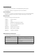
5.6 Print Position versus Cutter Position (TM-70) The following illustration shows the relationship between print position and cutter position. Manual cutter position Autocutter blade position Approx. 30 mm Approx. 13 mm Center position for the head Print direction Figure 5-24 Print position versus cutter position Note: The values in the figure are center values. The margins vary, due to paper slack or paper variations from piece to piece.
TM-T70 Technical Reference Guide 5.7 Overview of External Dimensions (TM-T70) 5.7.1 External Dimensions Approx. 114mm {4.49"} ❏ Width Approx. 125mm {4.92"} ❏ Depth Approx. 194mm {7.64"} ❏ Weight Approx. 1.8 kg {3.97 lb} (without roll paper) [Units: mm] ❏ Height Figure 5-25 Dimensions Figure 5-26 When the optional OT-CC70 is installed Rev.
5.8 Operating Specifications (TM-T70) Table 5-23 Temperature and humidity Item Temperature/ Humidity Acoustic noise Specifications Operating: 5 to 45°C (41 to 113°F), 10 to 90% RH no condensation allowed. (Refer to ambient operating ranges in the figure below.) Storage: (shipped packed state) –10 to +50°C (14 to 122°F), 10 to 90% RH (excluding paper) Operating: Approximately 55 dB (Bystander position) NOTE: The values above are measured in the Epson evaluation condition.
TM-T70 Technical Reference Guide Appendix A Interfaces and Connectors A.1 RS-232 Serial Interface A.1.
A.1.2 Functions of each Connector Pin Table A-2 Pin assignments Pin no. Signal name Signal direction 1 FG 2 TXD Output Transmission data 3 RXD Input Reception data 4 RTS Output Equivalent to DTR signal (pin 20) 6 DSR Input This signal indicates whether the host computer can receive data. SPACE indicates that the host computer can receive data. MARK indicates that the host computer cannot receive data.
TM-T70 Technical Reference Guide A.1.4 Code The hexadecimal numbers corresponding to the XON/XOFF codes are shown below. ❏ XON code: 11H ❏ XOFF code: 13H Note: When the printer goes from offline to online and the receive buffer is full, XON is not transmitted. When the printer goes from online to offline and the receive buffer is full, XOFF is not transmitted.
Reverse mode The transfer of status data from the printer to the host proceeds in the nibble or byte mode. This mode allows data transfer from an asynchronous printer under the control of the host. Data transfers in the nibble mode are made via the existing control lines in units of four bits (a nibble). In the byte mode, data transfer proceeds by making the 8-bit data lines bidirectional. Both modes fail to proceed concurrently in the compatibility mode, thereby causing half-duplex transmission.
TM-T70 Technical Reference Guide A.2.
Note: A signal name with a rule above it indicates an “L” active signal. Bidirectional communications cannot take place, unless all signal names for both sides correspond to each other. Connect all signal lines using a twisted-pair cable. Connect the return side to the signal ground level. Make sure the signals satisfy electrical characteristics. Set the leading edge and trailing edge times to 0.5 µs or less. Do not ignore Ack or BUSY signals during a data transfer.
TM-T70 Technical Reference Guide Appendix B Options and Consumables B.1 Roll Paper The table below shows the roll paper specifications. Table B-1 Paper specifications Type of paper Specified thermal paper Shape Roll Paper width Select from the following: ❐ 79.5 mm ± 0.5 mm (default) Roll core Internal diameter Outer diameter 12 mm {0.47"} 18 mm {0.71"} External dimensions Outer diameter 83 mm {3.
B.2.1.2 Case specifications ❏ Dimensions: 68 mm (D) × 136 mm (L) × 33 mm (H) (excluding projections) {2.68" × 5.35" × 1.26"} Refer to the figure below. Approx. 0.4 kg {14.11 oz} (excluding the AC cable) Durability level: V0 Black (matte) ❏ Weight: ❏ Material: ❏ Color: 136 68 33 Figure B-1 Case specifications B.2.1.3 Material No specific brominated flame retardants, such as PBBE and PBB, are used in this product. B.2.1.4 AC cable selection ❏ Select an AC cable that satisfies the following conditions.
TM-T70 Technical Reference Guide Appendix C Character Code Tables C.1 Page 0 (PC437: USA, Standard Europe) DC4 (International character set: when “America” is selected) Note: The character code tables show only character configurations. They do not show the actual print pattern. Rev.
C.2 Page 1 (Katakana) C-2 Character Code Tables Rev.
TM-T70 Technical Reference Guide C.3 Page 2 (PC850: Multilingual) Rev.
C.4 Page 3 (PC860: Portuguese) C-4 Character Code Tables Rev.
TM-T70 Technical Reference Guide C.5 Page 4 (PC863: Canadian-French) Rev.
C.6 Page 5 (PC865: Nordic) C-6 Character Code Tables Rev.
TM-T70 Technical Reference Guide C.7 Page 16 (WPC1252) Rev.
C.8 Page 17 (PC866: Cyrillic #2) C-8 Character Code Tables Rev.
TM-T70 Technical Reference Guide C.9 Page 18 (PC852: Latin2) Rev.
C.10 Page 19 (PC858: Euro) C-10 Character Code Tables Rev.
TM-T70 Technical Reference Guide C.11 Page 255 (Blank Page) UD: undefined Rev.
C.12 International Character Set C-12 Character Code Tables Rev.
EPSON SEIKO EPSON CORPORATION Printed in Japan