TM-T85/T85P Using this online operator’s guide The words on the left side of this screen are bookmarks for all the topics in this guide. Use the scroll bar next to the bookmarks to find any topic you want. Click a bookmark to instantly jump to its topic. (If you wish, you can increase the size of the bookmark area by dragging the dividing bar to the right.) Use the zoom tools to magnify or reduce the page display. Click the Find button if you want to search for a particular term.
thermal line printer TM-T85/T85P Operator’s Manual 400471502
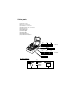
Printer parts (1) Printer cover (2) Power connector (3) Interface connector (4) Drawer kick-out connector (5) DIP switches (6) POWER light (7) ERROR light (8) PAPER light (9) POWER button (10) PAPER FEED button (1) (2) (3) (4) TM-T85 (5) DIP Switch 1 (2) DIP Switch 2 (3) (4) TM-T85P (5) DIP Switch 1 Control Panel (7) (6) (9) (8) (10)
All rights reserved. No part of this publication may be reproduced, stored in a retrieval system, or transmitted in any form or by any means, mechanical, photocopying, recording, or otherwise, without the prior written permission of Seiko Epson Corporation. No patent liability is assumed with respect to the use of the information contained herein. While every precaution has been taken in the preparation of this book, Seiko Epson Corporation assumes no responsibility for errors or omissions.
EMC and Safety Standards Applied Product Name: TM-T85/TM-T85P Model Name: M65TA / M116A The following standards are applied only to the printers that are so labeled.(EMC is tested using the EPSON power supply.) Europe: CE marking Safety: EN60950 North America: EMI: FCC/ICES-003 Class A Safety standards: UL 1950 CSA C22.2 No.
FCC Compliance Statement For American Users This equipment has been tested and found to comply with the limits for a Class A digital device, pursuant to Part 15 of the FCC Rules. These limits are designed to provide reasonable protection against harmful interference when the equipment is operated in a commercial environment.
iv
Introduction The TM-T85 and TM-T85P are one-station printers for issuing coupons, ECR and POS use which can be used for printing the results of weighing or measuring.
❏ Bidirectional parallel interface in accordance with the IEEE 1284 Nibble/Byte Modes Please be sure to read the instructions in this manual carefully before using your new EPSON printer.
About This Manual Setting Up and Using ❏ Chapter 1 contains information on unpacking the printer, setting it up, setting the DIP switches, and adjusting the paper near end detector. ❏ Chapter 2 contains information on using the printer. ❏ Chapter 3 contains troubleshooting information. Reference ❏ Chapter 4 contains specifications and character code tables. Notes, Cautions, and Warnings Note: Notes have important information and useful tips on the operation of your printer.
Contents Chapter 1 Installation Unpacking . . . . . . . . . . . . . . . . . . . . . . . . . . . . . . . . . . . . . . . . . . . . . . . . . . . . . . . . . . . . 1-1 Removing the Transportation Spacer . . . . . . . . . . . . . . . . . . . . . . . . . . . . . . . . . . . . . 1-2 Connecting the Printer to the Computer . . . . . . . . . . . . . . . . . . . . . . . . . . . . . . . . . . 1-4 Connecting the Printer to the Drawer . . . . . . . . . . . . . . . . . . . . . . . . . . . . . . . . . . . . .
Chapter 1 Installation Unpacking The illustration below shows the items included for the standard specification printer. Paper roll (1 pc) Printer Hexagonal lock screws (2 pcs) (only for the serial interface) If any item is missing or damaged, please contact your dealer for assistance. Note: See the Note on page 1-4 for information about the screws.
Removing the Transportation Spacer The printer is protected during shipping by a spacer that must be removed before you turn on the printer. 1. First, open the printer cover; next, push the auto cutter holder back and open the auto cutter; then open the head open lever, as shown by the arrows below.
2. Next, remove the orange transportation spacer as shown by the black arrow in the illustration below. Then place the transportation spacer in the storage space provided on the printer as shown by the white arrow. Note: Put the transportation spacer back in its original position if you ever ship or store your printer. 3. Close the head open lever and the auto cutter. When you close the auto cutter, press firmly until it clicks.
Connecting the Printer to the Computer You need an appropriate serial interface cable to connect your computer to the printer. TM-T85 1. Make sure that the printer and the computer are turned off. Then plug the cable into the connector on the printer, as shown. Note: Your printer comes with inch-type hexagonal lock screws installed.
TM-T85P You need an appropriate parallel interface cable to connect your computer to the printer. 1. Make sure that the printer and the computer are turned off. Then plug the cable into the connector on the printer, as shown. Note: Squeeze the wire clips on the printer together until they lock in place on both sides of the connector. 2. Connect the other end of the cable to the connector on your computer.
Connecting the Printer to the Drawer Plug the drawer cable into the drawer kick-out connector on the bottom of the printer next to the computer interface connector. TM-T85 TM-T85P CAUTION: Do not connect a telephone line to the drawer kick out connector.
Den Drucker an die Lade anschließen Das Kabel der Lade an die Schnappsteckerbuchse (neben der Schnittstellenbuchse) an der Uinterseite des Druckers anschließen. TM-T85 TM-T85P ACHTUNG: Kein Telefonkabel an die Schnappsteckerbuchse anschließen.
Grounding the Printer You need a ground wire to ground your printer. Recommended wire is described below. Thickness of wire: Diameter of terminal to be attached: AWG 18 or equivalent 3.2 1. Make sure that the printer is turned off. 2. Connect the ground wire to the printer using the FG screw on the bottom of the printer, as shown.
Connecting the Power Supply This printer requires an external power supply. The Epson Power Supply PS-150 is recommended. CAUTION: Using an incorrect power supply can cause serious damage to the printer. 1. Make sure that the power supply is turned off. 2. Plug the power supply’s cable into the printer’s connector as shown below. Note that the flat side of the connector faces down. TM-T85 TM-T85P 3. Plug the power supply’s cord into an outlet.
Arranging the Interface Cable After you have plugged in all the cables, put the interface cable between the feet on the bottom of the printer and the cable-holding posts, as shown in the illustration below. This helps keep the cable securely fastened. Installing the Paper Roll The procedure describes how to install a paper roll for the first time. If you are replacing a used-up paper roll, see page 2-2. Note: Be sure to use roll paper that meets the specifications. 1. Open the printer cover.
2. Spread the roll paper holder and insert the paper roll as shown. 3. Be sure to note the correct direction that the paper comes off the roll. 4. Hold both edges of the paper and insert it straight into the paper slot. Push the paper into the paper slot until the printer feeds the paper automatically and it comes out of the paper exit.
Note: The paper is cut by the auto cutter. Note: If paper is inserted incorrectly, it may wrinkle. If it wrinkles, feed the paper with the PAPER FEED button until it is smooth.
5. Remove the cut paper and close the printer cover. Running the Self Test Any time that you want to check the performance of your printer you can run the self test described below. This shows whether your printer is working correctly. It is independent of any other equipment or software. 1. To perform the self test, close the printer cover if it is open and hold down the PAPER FEED button while you turn on the printer with the POWER button. 2.
3. Press the PAPER FEED button to start the second part of the test, in which the printer prints a pattern using the built-in character set. It also performs several partial cuts and prints the following: *** completed *** 4. Then it performs a full cut and enters the normal mode. Part of a sample self test is shown below: TM-T85 TM-T85P Setting the DIP Switches You can change the print density or any of your interface settings by changing the DIP switch settings. 1. Make sure that the printer is off.
2. Turn the printer over and remove the DIP switch access cover, as shown below. TM-T85 DSW 2 DSW 1 TM-T85P DSW 1 3. Notice that ON is marked on the switches. Use tweezers or another narrow tool to move the switches.
4. Use the following tables to set the DIP switches. Numbers starting with 1 are in the first set, and numbers starting with 2 are in the second (only for TM-T85).
DIP Switch Set 2 Switch 2-4 Function ON OFF Normally OFF Reserved.
Print Density Switch Switch Function 4 5 ON ON 2 OFF OFF 3 ON OFF OFF ON 1 4 Light Dark Note: If you change any DIP switch settings while the printer is turned on, the new settings will not take effect until you turn the printer off and back on or reset it (except for the DIP switches 2-7 and 2-8 of the TM-T85). 5. Replace the DIP switch cover and secure it with the screw.
Adjusting the Paper Near End Detector The paper near end detector detects when the paper is almost gone by measuring the diameter of the paper roll. Software programs can use the ESC c 4 command to stop printing when the paper is almost gone. If you want to change the amount of paper remaining when the printer stops printing, follow the steps below to adjust the paper near end detector. Note: The printer also has a paper end-detector that stops the printer at the very end of a roll.
4. Move the positioning plate to the appropriate position and then tighten the adjusting screw, as shown below. Position 1 leaves the least paper on the roll, and position 6 leaves the most. Detecting lever The table below shows the approximate amount of adjustment of the diameter for each position. Adjustment Position Number Adjustment amount 1 Approx. 0 mm (0 in) 2 Approx. 2 mm (0.08 in) 3 Approx. 4 mm (0.16 in) 4 Approx. 6 mm (0.24 in) 5 Approx. 8 mm (0.32 in) 6 Approx. 10 mm (0.39 in) 5.
Affixing the Fastening Tape (Optional) Two sets of tape are included as an option to fasten your printer to a countertop or other surface. Follow the steps below: 1. Clean the countertop or other surface where the printer will be installed. 2. Peel the green backing paper off of one side of each of the two sets of tape and affix them to the bottom of the printer, as shown below. 3. Peel the other green backing paper off of the sets of tape. 4.
Chapter 2 Using the Printer The control panel has two buttons and three lights. Buttons POWER This button turns the printer on and off. PAPER FEED This button can be disabled by the ESC c 5 command. Press this button once to advance the paper one line. Press and hold this button down to feed the paper continuously. Note: You also use this button to execute a macro and to print the second part of the self test.
❏ In the macro ready mode. ERROR This light is on when the printer is off line. It blinks to indicate an error condition. The blinking pattern shown below indicates that the temperature of the print head is too high. The printer recovers automatically and resumes printing when the head cools. Approximately 160 ms Approximately 2.56 sec The blinking pattern shown below indicates a paper jam in the auto cutter.
2. Pull up on the paper and cut it with scissors. Then press the PAPER FEED button to remove the cut paper. Cut 3. Spread the roll paper holder and remove the paper roll as shown.
4. Spread the roll paper holder and insert the paper as shown. 5. Be sure to note the correct direction that the paper comes off the roll. 6. Hold both edges of the paper and insert it straight into the paper slot. Push the paper into the paper slot until the printer feeds the paper automatically and it comes out of the paper exit.
Note: The paper is cut by the auto cutter. Note: If paper is inserted incorrectly, it may wrinkle.
7. Remove the cut paper and close the printer cover.
Chapter 3 Troubleshooting This chapter gives the solutions to some of the more common printer problems. Power problems The POWER light does not come on. Make sure that the power supply cables are correctly plugged into the printer, the power unit, and the power outlet. Make sure that power is supplied to the power outlet. If the outlet is controlled by a switch or timer, use another outlet. Printing problems The ERROR light is on (not flashing) and nothing is printed.
3. Clean the print head with a cotton swab moistened with alcohol. CAUTION: Be sure that you do not touch the print head with your fingers because you can damage it. 4. Close the head open lever and the auto cutter. When you close the auto cutter, press firmly until it clicks. Note: To prevent paper jams, make sure that the auto cutter tab is underneath the auto cutter holder as shown on the auto cutter label. Paper handling problems The paper is jammed inside the printer.
3. Pull up on the paper roll and cut the paper with scissors so that is straight as shown below. Remove the jammed paper carefully in the paper feeding direction. Cut CAUTION: Do not touch the print head. You can damage it. 4. Close the head open lever. 5. Close the auto cutter. When you close it, press firmly until it clicks. Note: To prevent paper jams, make sure that the auto cutter tab is underneath the auto cutter holder as shown on the auto cutter label. 6. Re-load the paper.
If you have trouble re-loading the paper, the auto cutter blade may be in the wrong position. See the illustration below for the correct position. If the blade is not in this position, insert a cross-head screwdriver in the hole on the right side of the auto cutter unit and turn the gear inside to return the cutter blade to its normal position. See the illustration below.
The remaining amount of roll paper is not detected correctly. A microswitch attached to the paper roll near end detector lever detects when the roll paper is almost gone. You can adjust the detector lever if necessary. See Chapter 1 for instructions. Hexadecimal Dump This feature allows experienced users to see exactly what data is coming to the printer. This can be useful in finding software problems.
❏ A period (.) is printed for each code that has no ASCII equivalent. ❏ Control codes are printed in bold for emphasis. ❏ During the hex dump all commands except DLE EOT and DLE ENQ are disabled. 6. Open the cover to set the printer off line so that it will print the last line. 7. Close the cover and turn off the printer or reset it to turn off the hex dump mode.
Chapter 4 Reference Information Printing Specifications Printing Method: Thermal line printing Dot Density: 180 x 180 dpi Printing Direction: Unidirectional with friction feed Printing width: 72mm (2.83"), 512 dot positions Characters/line (default): Font A: 42, Font B: 56 Character spacing (default) Fonts A and B: 2 dots: 0.28mm(.01") Programmable by control command Printing speed: Approx. 12 lines/second (1/6”feed) Approx. 50 mm( 2")/second continuous feed Approx. 28 mm(1.
Character Specifications Number of characters Alphanumeric characters: 95 Extended graphics: 128 x 7 pages, including 1 space page International characters: 32 Character structure: 12 x 24 (Font A) incl. 2-dot spacing in horizontal 9 x 24 (Font B) incl. 2-dot spacing in horizontal Font A is the default Font A: 1.41mm (.06") x 3.39mm (.13") (WxH) Font B: 0.99mm (.04") x 3.39mm (.
Paper Specifications Paper type: Specified thermal paper roll Paper width +0" 80 +0 –1 mm (3.15” –0.04" ) Roll paper specifications Total dia: 83mm max Core dia: Inside: 12mm Outside: 18mm Paper must not be pasted to the core paper NTP080-80 (Nakagawa Seisakujo) [Original paper: Nippon Paper Industries Co., Ltd.
Environmental Conditions Temperature Operating 5 to 40 ° C (41 to 104 ° F) Storage –10 to 50 ° C (14 to 122° F) except for paper Humidity Operating 30 to 85% RH Storage 30 to 90% RH except for paper Interface Specifications Serial interface: RS-232 compatible Parallel interface: IEEE 1284 compatible (Nibble/Byte Modes) Note: The interface is a factory installed option. One of the interfaces (serial or parallel) is already installed. Note: Refer to the EPSON TM-T85/T85P Specification for details.
Character Code Tables Page 0 (PC437: U.S.A., Standard Europe)(International character set: U.S.A.
Page 1 (Katakana) 4-6 Reference Information
Page 2 (PC850: Multilingual) Reference Information 4-7
Page 3 (PC860: Portuguese) 4-8 Reference Information
Page 4 (PC863: Canadian-French) Reference Information 4-9
Page 5 (PC865: Nordic) 4-10 Reference Information
Page 255 (Space Page) Reference Information 4-11
International character sett Country ASCII code (hexadecimal) Hex 23 24 40 5B 5C 5D 5E 60 7B 7C 7D 7E Dec 35 36 64 91 92 93 94 96 123 124 125 126 U.S.A. # $ @ [ \ ] ^ ` { ¦ } ~ France # $ à ° ç § ^ ` é ù è ¨ Germany # $ § Ä Ö Ü ^ ` ä ö ü ß U.K.
Chapter 5 Commands Command Notation [Name] [Format] The name of the command. The code sequence. ASCII indicates the ASCII equivalents. Hex indicates the hexadecimal equivalents. Decimal indicates the decimal equivalents. [ ]k indicates the contents of the [ ] should be repeated k times. [Range] Gives the allowable ranges for the arguments. [Description] Describes the function of the command. [Notes] Provides important information on setting and using the printer command, if necessary.
Control Commands HT [Name] [Format] Horizontal tab ASCII HT Hex 09 Decimal 9 [Description] Moves the print position to the next horizontal tab position. [Notes] • This command is ignored unless the next horizontal tab position has been set. • If the next horizontal tab position exceeds the printing area, the printer sets the printing position to [Printing area width + 1]. • Horizontal tab positions are set with ESC D.
CR [Name] [Format] Print and carriage return ASCII CR Hex 0D Decimal 13 [Description] When auto-line feed is enabled, this command functions in the same way as LF. When auto-line feed is disabled, this command is ignored. [Notes] • This command sets the print position to the beginning of the line. • This command is available only with a parallel interface and is ignored with a serial interface.
• When Auto Status Back (ASB) is enabled using the GS a command, the status transmitted by the DLE EOT command and the ASB status must be differentiated. • If the value of n is out of the specified range, the printer ignores this command. n = 1: Printer status Bit Off/On Hex Decimal Function 0 Off 00 0 Not used. Fixed to Off. 1 On 02 2 Not used. Fixed to On. Off 00 0 Drawer open/close signal is LOW (connector pin 3). On 04 4 Drawer open/close signal is HIGH (connector pin 3).
Bit Off/On Hex Decimal Function Off 00 0 No error. On 40 64 Error occurs. Off 00 0 Not used. Fixed to Off. 6 7 Bit 5: Becomes on when printing stops due to paper-end detected by the paper roll end sensor or due to a paper near-end enabled by using the ESC c 4. n = 3: Error status Bit Off/On Hex Decimal Function 0 Off 00 0 Not used. Fixed to Off. 1 On 02 2 Not used.Fixed to On. 2 - - - Undefined. Off 00 0 No auto-cutter error. On 08 8 Auto-cutter error occurs.
Bit Off/On Hex Decimal Function 3 On 0C 12 Paper near-end is detected by the paper roll nearend sensor. 4 On 10 16 Not used. Fixed to On. 5 Off 00 0 Paper roll end sensor. Paper present. 6 On 60 96 Paper end is detected by the paper roll end sensor. 7 Off 00 0 Not used. Fixed to Off.
[Reference] • Even if DLE ENQ 2 is executed, the printer retains the settings (by ESC !, ESC 3, etc.) that were in effect when the error occurred. The printer can be initialized completely by using DLE ENQ and ESC @. DLE EOT CAN [Name] [Format] Cancel print data in page mode ASCII CAN Hex 18 Decimal 24 [Description] In page mode, deletes all the print data in the current printable area. [Notes] • This command is enabled only in page mode.
[Default] [Reference] • The horizontal and vertical motion unit are specified by GS P. Changing the horizontal or vertical motion unit does not affect the current right-side spacing. • The horizontal and vertical motion unit are specified by GS P. Changing the horizontal or vertical motion unit does not affect the current right-side spacing. • The GS P command can chahge the horizotal (and vertical) motion unit.
Bit Off/On Hex Decimal Function Off 00 0 Double-height mode not selected. On 10 16 Double-height mode selected. Off 00 0 Double-width mode not selected. On 20 32 Double-width mode selected. - - - Undefined. Off 00 0 Underline mode not selected. On 80 128 Underline mode selected. 4 5 6 7 [Notes] [Default] [Reference] • Determine the values of n by adding the values of all the characteristics you want to select.
[Notes] [Reference] 5-10 Commands • The distance from the beginning of the line to the print position is [(nL + nH ✕ 256) ✕ (vertical or horizontal motion unit)] inches. • Settings outside the specified printable area are ignored. • The horizontal and vertical motion unit are specified by GS P. • The GS P command can change the horizontal (and vertical) motion unit.
ESC % n [Name] [Format] Select/cancel user-defined character set ASCII ESC % n Hex 1B 25 n Decimal 27 37 n [Range] 0 ≤ n ≤ 255 [Description] Selects or cancels the user-defined character set. • When the Least Significant Bit (LSB) is 0, the user-defined character set is canceled. • When the LSB is 1, the user-defined character set is selected. [Notes] • When the user-defined character set is canceled, the internal character set is automatically selected.
[Default] [Reference] [Example] • A user-defined character and a downloaded bit image cannot be defined simultaneously. When this command is executed, the downloaded bit image is cleared. • The user-defined character definition is cleared when: Esc@ is executed. GS ✽ is executed. ESC ? is executed. The printer is reset or the power is turnde off. The internal character set ESC %, ESC ? • When font A is selected.
ESC ✽ m nL n H [d]k [Name] [Format] Select bit-image mode ✽ ASCII ESC m nL nH [d]k Hex 1B 2A m nL nH [d]k Decimal 27 42 m nL nH [d]k [Range] m = 0, 1, 32, 33 0 ≤ nL ≤ 255 0 ≤ nH ≤ 3 0 ≤ d ≤ 255 [Description] Selects a bit-image mode using m for the number of dots specified by nL and nH, as follows: Vertical Direction Horizontal Direction (*1) m Mode Number of Dots Dot Density Dot Density Number of Data (K) 0 8-dot single-density 8 60 DPI 90 DPI nL + nH ✕ 256 1 8-dot double-density 8 60 DPI
• After printing a bit image, the printer returns to normal data processing mode. • This command is not affected by print modes (emphasized, doublestrike, and underline, etc.), except upside-down mode.
• The relationship between the image data and the dots to be printed is as follows: Bit-image data 8-dot bit image d1 d2 d3 MSB d1 Bit-image data d2 d3 Print data ❏ = 1 dot LSB Print data 24-dot bit image Bit-image data d1 d2d3 d4d5d6 d7d8 d9 MSB d1 d2 d3 Bit-image data Print data ❏ = 1 dot LSB Single density Double density Commands 5-15
ESC - n [Name] [Format] Turn underline mode on/off ASCII ESC n Hex 1B 2D n Decimal 27 45 n [Range] 0 ≤ n ≤ 2, 48 ≤ n ≤ 50 [Description] Turns underline mode on or off, based on the following values of n. n Function 0, 48 Turns off underline mode 1, 49 Turns on underline mode (1-dot thick) 2, 50 Turns on underline mode (2-dots thick) [Notes] [Default] [Reference] • The printer can underline all characters (including right-side character spacing), but cannot underline the space set by HT.
Decimal 27 51 n [Range] 0 ≤ n ≤ 255 [Description] Sets the line spacing to [n x vertical or horizontal motion unit] inches. [Notes] • The line spacing can be set independently in standard mode and in page mode. • The horizontal and vertical motion unit are specified by GS P. Changing the horizontal or vertical motion unit does not affect the current line spacing. • The GS P command can change the horizontal (and vertical) motion unit.
Bit Off/On Hex Decimal Function 2 - - - Undefined. 3 - - - Undefined. 4 - - - Undefined. 5 - - - Undefined. 6 - - - Undefined. 7 - - - Undefined. [Notes] [Default] [Reference] • When the printer is disabled, it ignores all data except for errorrecovery commands (DLE ENQ 1, DLE ENQ 2) until it is enabled by this command.
• The macro definition is not cleared. ESC D [n] k NUL [Name] [Format] Set horizontal tab positions ASCII ESC D [n] k NUL Hex 1B 44 [n] k 00 Decimal 27 68 [n] k 0 [Range] 1 ≤ n ≤ 255 0 ≤ k ≤ 32 [Description] Sets horizontal tab positions. • n specifies the column number for setting a horizontal tab position from the beginning of the line. • k indicates the total number of horizontal tab positions to be set.
[Notes] [Default] [Reference] • When the LSB of n is 0, emphasized mode is turned off. • When the LSB of n is 1, emphasized mode is turned on. • Bit image and downloaded bit image , and bar code cannot be emphasized. • ESC ! also turns on and off emphasized mode. However, the last received command is effective. n=0 ESC ! ESC G n [Name] [Format] Turn on/off double-strike mode ASCII ESC G n Hex 1B 47 n Decimal 27 71 n [Range] 0 ≤ n ≤ 255 [Description] Turns double-strike mode on or off.
[Reference] • In standard mode, the printer uses the vertical motion unit (y). • When this command is used in page mode, the command functions as follows, depending on the starting position of the printable area. ➀ When the starting position is set to the upper left or lower right of the printable area using ESC T, the vertical motion unit (y) is used. ➁ When the starting position is set to the upper right or lower left of the printable area using ESC T, the horizontal motion unit (x) is used.
[Reference] FF, CAN,ESC, FF, ESC S, ESC T, ESC W, GS $, GS\ ESC R n [Name] [Format] Select an international character set ASCII ESC R n Hex 1B 52 n Decimal 27 82 n [Range] 0 ≤ n ≤ 10 [Description] Selects an international character set n from the following table: n Character set 0 U.S.A. 1 France 2 Germany 3 U.K.
[Reference] • This command switches the settings for the following commands (in which the values can be set independently in standard mode and page mode) to those for standard mode: ➀ Set right-side character spacing: ESC SP ➁ Select 1/6-inch line spacing: ESC 2 ➂ Set line spacing: ESC 3 FF, ESC FF, ESC L ESC T n [Name] [Format] Select print direction in page mode ASCII ESC T n Hex 1B 54 n Decimal 27 84 n [Range] 0≤n≤3 48 ≤ n ≤ 51 [Description] Selects the print direction and starting position in page mo
[Default] [Reference] ➁ If the starting position is the upper right or lower left of the printing area, data is buffered in the paper feed direction: Commands using horizontal motion units: ESC 3, ESC J, GS $, GS \ Cmmands using vertical motion units: ESC SP, ESC $, ESC \ n=0 ESC $, ESC L, ESC W, ESC \, GS $, GS P, GS \ ESC V n [Name] [Format] Turn 90° clockwise rotation mode on/off ASCII ESC V n Hex 1B 56 n Decimal 27 86 n [Range] 0 ≤ n ≤ 1, 48 ≤ n ≤ 49 [Description] Turns 90° clockwise rotation mode on
[Notes] • • • • • • • • • x0 = [(xL + xH ✕ 256) ✕ (horizontal motion unit)] y0 = [(yL + yH ✕ 256) ✕ (vertical motion unit)] dx = [dxL + dxH ✕ 256) ✕ (horizontal motion unit)] dy = [dyL + dyH ✕ 256) ✕ (vertical motion unit)] The printing area is set as shown in the figure below. If this command is input in standard mode, the printer executes only internal flag operation. This command does not affect printing in standard mode.
• When the horizontal starting position , vertical starting position, printing area width, and printing area height are defined as X, Y, Dx, and Dy respectively, the printing area is set as show in the figure on the next page. (0, 0) Paper feed direction paper (x, y) Dy Dx Printing area (X+DX-1, *Y + Dy=1) [Default] [Reference] • The printable area for this printer is 512/180 inches in the horizontal direction and 1662/360 inches in the vertical direction.
[Reference] • The print starting position moves from the current position to [N ✕ horizontal or vertical motion unit] • The horizontal and vertical motion unit are specified by GS P. • The GS P command can change the horizontal (and vertical) motion unit. However, the value cannot be less than the minimum horizontal movement amount, and it must be in even units of the minimum horizontal movement amount. • In standard mode, the horizontal motion unit is used.
Left justification Centering ABC Right justification ABC ABC ABCD ABCD ABCD ABCDE ABCDE ABCDE ESC c 3 n [Name] [Format] Select paper sensor(s) to output paper end signals ASCII ESC c 3 n Hex 1B 63 33 n Decimal 27 99 51 n [Range] 0 ≤ n ≤ 255 [Description] selects paper sensor(s) to output paper end signals, using n as follows: Bit Off/On Hex Decimal Function Off 00 0 Paper roll near-end sensor disabled. On 01 1 Paper roll near-end sensor enabled.
[Notes] [Default] • It is possible to select multiple sensors to output signals. Then, if any of the sensors detects a paper end, the paper end signal is output. • This command is available only with a parallel interface and is ignored with a serial interface. • Sensor is switched when executing this command. Because of this, the paper-out signal switching may delay depending on the receive buffer state.
ESC c 4 n [Name] [Format] Select paper sensor(s) to stop printing ASCII ESC c 4 n Hex 1B 63 34 n Decimal 27 99 52 n [Range] 0 ≤ n ≤ 255 [Description] Selects the paper sensor(s) used to stop printing when a paper-end is detected, using n as follows: Bit Off/On Hex Decimal Function Off 00 0 Paper roll near-end sensor disabled. On 01 1 Paper roll near-end sensor enabled. Off 00 0 Paper roll near-end sensor disabled. On 02 2 Paper roll near-end sensor enabled. 2 - - - Undefined.
[Notes] [Default] • When the panel buttons are disabled, none of them are usable when the printer cover is closed. • In this printer, the panel button is the PAPER FEED button. • When the printer cover is open, the PAPER FEED button is enabled regardless of the settings of this command. • In the macro ready mode, the PAPER FEED button is enabled regardless of the settings of this command; however, the paper can not be fed by using this button.
0 ≤ t1 ≤ t2 ≤ 255 [Description] Outputs the pulse specified by t1 and t2 to connector pin m as follows: m Connector pin 0, 48 Drawer kick-out connector pin 2 1, 49 Drawer kick-out connector pin 5 [Notes] • The pulse ON time is [t1 ✕ 2 ms] and the OFF time is [t2 ✕ 2 ms]. • If t2 < t1, the OFF time is [t1 ✕ 2 ms] ESC t n [Name] [Format] Select character code table ASCII ESC t n Hex 1B 74 n Decimal 27 116 n [Range] 0 ≤ n ≤ 5, n = 255 [Description] Selects a page n from the character code table.
[Description] Transmits the status of connector pin n, using n as follows: n Connector pin 0, 48 Drawer kick-out connector pin 3 [Notes] Bit • When DTR/DSR control is selected, the printer transmits only 1 byte after confirming that the host is ready to receive data (DSR signal is SPACE). If the host computer is not ready to receive data (DSR signal is MARK), the printer keeps waiting until the host is ready.
[Notes] • When DTR/DSR control is selected, the printer transmits only 1 byte after confirming that the host is ready to receive data (DSR signal is SPACE). If the host computer is not ready to receive data (DSR signal is MARK), the printer waits until the host is ready. When XON/ XOFF control is selected, the printer transmits only 1 byte without checking the DSR signal. • This command is executed when the data is processed in the receive buffer.
[Notes] [Default] [Example] • When the LSB of n is 0, upside-down printing mode is turned off. • When the LSB of n is 1, upside-down printing mode is turned on. • This command is enabled only when input at the beginning of a line. • When this command is input in page mode, the printer performs only internal flag operations. • This command does not affect printing in page mode. • In upside-down printing mode, the printer rotates the line to be printed by 180° and then prints it.
Table 1 Character Width Selection Table 2 Character Height Selection Hex Decimal Width Hex Decimal Height 00 0 1 (normal) 00 0 1 (normal) 10 16 2 (double-width) 01 1 2 (double-hight) 20 32 3 02 2 3 30 48 4 03 3 4 40 64 5 04 4 5 50 80 6 05 5 6 60 96 7 06 6 7 70 112 8 07 7 8 [Notes] [Default] [Reference] • This command is effective for all characters (except for HRI characters). • It n is outside of the defined range, this command is ignored.
‘ [Reference] • The horizontal starting buffer position does not move. • The reference starting position is that specified by ESC T. • This command operates as follows, depending on the starting position of the printing area specified by ESC T: ➀ When the starting position is set to the upper left or lower right, this command sets the absolute position in the vertical direction.
• The figure below shows the relationship between the bit-image data and dots to be defined. x ✕ 8 dots d1 dy + 1 MSB dy ✕ 2 + 1 y ✕ 8 dots LSB dy dy ✕ 2 [Reference] dx ✕ y ✕ 8 GS / GS / m [Name] [Format] Print downloaded bit image ASCII GS / m Hex 1D 2F m Decimal 29 47 m [Range] 0 ≤ m ≤ 3, 48 ≤ m ≤ 51 [Description] Prints a downloaded bit image in mode m.
[Reference] • If the width of the printing area set by GS L and GS W less than the width required by the data sent with the GS / command, the following will be performed on the line in question (but the printing cannot exceed the maximum printable area): ➀ The width of the printing area is extended to the right to accommodate the amount of data. ➁ If ➀ step does not provide sufficient width for the data, the left margin is reduced to accommodate the data.
[Notes] • When the LSB of n is 1, white/black reverse mode is turned on. • In white/black reverse printing mode, print dots and non-print dots are reversed. (Characters are printed in white on a black background.) • This command is available for built-in characters and user-defined characters. • When white/black reverse printing mode is on, it also applied to character spacing set by ESC SP.
Decimal 29 73 n 1 ≤ n ≤ 3, 49 ≤ n ≤ 51 Transmits the printer ID specified by n as follows: [Range] [Function] n Printer ID Specification ID (hexadecimal) 1, 49 Printer model ID TM-T85/T85P 08H 2, 50 Type ID See table below. 3, 51 ROM version ID Depends on ROM version n = 2, Type ID Bit Off/On Hex Decimal Function 0 Off 00 0 Two-byte character code not supported. 1 On 02 2 Auto-cutter equipped. 2 - - - Undefined. 3 - - - Undefined. 4 Off 00 0 Not used.
0 ≤ nL ≤ 255 0 ≤ nH ≤ 255 [Description] Sets the left margin using nL and nH. • The left margin is set to [(nL + nH ✕ 256) ✕ horizontal motion unit)] inches. [Range] Printable area Left margin Printing area width [Notes] [Default] [Reference] • This command is effective only at the beginning of a line. • If this command is input in page mode, the printer performs only internal flag operations. • This command does not affect printing in page mode.
[Default] [Reference] ➀ ➁ Command using y: ESC 3, ESC J • In page mode, the following commands use x or y, depending on character orientation: ➀ When the print starting position is set to the upper left or lower right of the printing area using ESC T (data is buffered in the direction perpendicular to the paper feed direction): Command using x: ESC SP, ESC $, ESCW, ESC\ Command using y: ESC 3, ESC J, ESC W, GS $, GS\ ➁ When the print starting position is set to the upper right or lower left of the printin
• In standard mode, this command is effective only at the beginning of a line. [Note for ➀] • When m = 1 or 49, this command operates the same way as ESC i. [Notes for ➁] • When n= 0, the printer feeds the paper to the cutting position and cuts it. • When n ≠ 0, the printer feeds the paper to (cutting position + [n ✕ vertical motion unit]) and cuts it. • The horizontal and vertical motion unit are specified by GS P. • The paper feed amount is calculated using the vertical motion unit (y).
• If the width set for the printing area is less than the width of one character, when the character data is developed, the following processing is performed: ➀ The set printing area width is extended to the right to accommodate one character. Printable area A Extended to right Left margin Printing area width set by nL and nH ➁ If the printing area width cannot be extended sufficiently, the left margin is reduced to accommodate one character.
[Notes] [Reference] • This command sets the distance from the current position to [(nL + nH ✕ 256) ✕ vertical or horizontal motion unit] inches. • This command is ignored Unless page mode is selected. • When pitch N is specified to the movement downward: nL + nH ✕ 256 = N When pitch N is specified to the movement upward (the negative direction), use the complement of 65536.
[Notes] [Reference] After waiting for the period specified by t, the LED indicator blinks and the printer waits for the PAPER FEED button to be pressed. After the button is pressed, the printer executes the macro once. The printer repeats the operation r times. • If this command is received while a macro is being defined, the macro definition is aborted and the definition is cleared. • If the macro is not defined or if r is 0, nothing is executed.
[Notes] • If any of the status items in the table above are enabled, the printer transmits the status when this command is executed. The printer automatically transmits the status whenever the enabled status item changes. The disabled status items may change, in this case, because each status transmission represents the current status. • If all status items are disabled, the ASB function is also disabled.
Second byte (error information) Bit Off/On Hex Decimal Status for ASB 0 - - - Undefined. 1 - - - Undefined. 2 - - - Undefined. Off 00 0 No auto-cutter error. On 08 8 Auto-cutter error. Off 00 0 Not used. Fixed to Off. Off 00 0 No unrecoverable error. On 20 32 Unrecoverable error. Off 00 0 No automatically recoverable error. On 40 64 Automatically recoverable error occurs. Off 00 0 Not used. Fixed to Off.
Forth byte (paper sensor information) Bit Off/On Hex Decimal Status for ASB 0 - - - Undefined. 1 - - - Undefined. 2 - - - Undefined. 3 - - - Undefined. 4 Off 00 0 Not used. Fixed to Off. 5 - - - Undefined. 6 - - - Undefined. 7 Off 00 0 Not used. Fixed to Off. [Default] [Reference] n = 0 when DIP SW 2-1 (serial interface) or DIP SW 1-3 (parallel interface) is off, n = 2 when DIP SW 2-1 (serial interface) or DIP SW 13 (parallel interface) is on.
[Description] Selects a font for the HRI characters used when printing a bar code. n selects a font from the following table: n Font 0, 48 Font A (12 × 24) 1, 49 Font B (9 × 24) [Note] [Default] [Reference] • HRI indicates Human Readable Interpretation. • HRI characters are printed at the position specified by GS H. n=0 GS H, GS K GS h n [Name] [Format] Select bar code height ASCII GS h n Hex 1D 68 n Decimal 29 104 n [Range] 0 ≤ n ≤ 255 [Description] Selects the height of the bar code.
m selects a bar code system as follows: m Bar Code System Number of Characters Remarks 0 UPC-A 11 ≤ k ≤ 12 48 ≤ d ≤ 57 1 UPC-E 11 ≤ k ≤ 12 48 ≤ d ≤ 57 2 JAN13 (EAN) 12 ≤ k ≤ 13 48 ≤ d ≤ 57 3 JAN 8 (EAN) 7 ≤ k ≤ 8 48 ≤ d ≤ 57 4 CODE39 1≤k 48 ≤ d ≤ 57, 65 ≤ d ≤ 90, 32, 36, 37, 43, 45, 46, 47 5 ITF 1 ≤ k (even number) 48 ≤ d ≤ 57 6 CODABAR 1≤k 48 ≤ d ≤ 57, 65 ≤ d ≤ 68 , 36, 43, 45, 46, 47, 58 65 UPC-A 11 ≤ n ≤ 12 48 ≤ d ≤ 57 66 UPC-E 11 ≤ n ≤ 12 48 ≤ d ≤ 57 67 JAN13 (EA
• When the bar code system used is UPC-A or UPC-E, the printer prints the bar code data after receiving 12 bytes bar code data and processes the following data as normal data. • When the bar code system used is JAN13, the printer prints the bar code after receiving 13 bytes bar code data and processes the following data as normal data. • When n the bar code system used is JAN8, the printer prints the bar code after receiving 8 bytes bar code data and processes the following data as normal data.
Hex 1D 72 n Decimal 29 114 n [Range] 1 ≤ n ≤ 2, 49 ≤ n ≤ 50 [Description] Transmits the status specified by n as, follows: n Function 1, 49 Transmits paper sensor status (same as ESC v) 2, 50 Transmits drawer kick-out connector status (same as ESC u 0) [Notes] • When DTR/DSR control is selected, the printer transmits only 1 byte after confirming the host is ready to receive data (DSR signal is SPACE).
Drawer kick-out connector status (n = 2, 50): Bi t Off/On Hex Decimal Status for ASB Off 00 0 Drawer kick-out connector pin 3 is LOW. On 01 1 Drawer kick-out connector pin 3 is HIGH. 1 - - - Undefined 2 - - - Undefined. 3 - - - Undefined. 4 Off 00 0 Not used. Fixed to Off. 5 - - - Undefined. 6 - - - Undefined. 7 Off 00 0 Not used. Fixed to Off.
[Default] [Reference] 5-56 Commands CODE39, ITF, CODABAR n=3 GS k