receipt printer TM-T88II Series Operator’s Manual 400852000
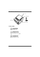
Printer Parts and Labels Printer cover Control panel PO WE ER R RO R P OU APE R FE T ED Cutter cover POWER ERROR PAPER OUT FEED Cover open button Caution Lables CAUTION: Thermal head is hot. ATTENTION: La téte thermique est chaude. VORSICHT: Der Thermalkopf ist heiß.
Labels Label inside cutter section Label inside printer cover Caution label above drawer kick-out connector.
Quick Reference This Quick Reference will direct you to key areas of this Operator’s Manual. For a complete listing of topics, see the Contents. Printer Parts and Labels Ordering Paper inside front cover page ix Where to order paper Setting Up the Printer page 1-1 How to set up the printer. Installing and Replacing Paper page 1-7 How to load or change the paper roll. Solving Problems page 3-1 How to correct problems.
All rights reserved. No part of this publication may be reproduced, stored in a retrieval system, or transmitted in any form or by any means, electronic, mechanical, photocopying, recording, or otherwise, without the prior written permission of Seiko Epson Corporation. No patent liability is assumed with respect to the use of the information contained herein. While every precaution has been taken in the preparation of this book, Seiko Epson Corporation assumes no responsibility for errors or omissions.
FCC CLASS A FCC Compliance Statement For American Users This equipment has been tested and found to comply with the limits for a Class A digital device, pursuant to Part 15 of the FCC Rules. These limits are designed to provide reasonable protection against harmful interference when the equipment is operated in a commercial environment.
DECLARATION OF CONFORMITY Product Name: Printer Model Name: M129B The printer conforms to the following Directives and Norms Directive 89/336/EEC EN 55022 (1987 and 1994 2nd/1995) Class B EN 50082-1 (1992) IEC 801-2 (1991) IEC 801-3 (1984) IEC 801-4 (1988) Directive 90/384/EEC EN45501: (1992) iv
EMI and Safety Standards Applied The following standards are applied only to the printers that are so labeled.
About This Manual Setting Up and Using ❏ Chapter 1 contains information on unpacking the printer and setting it up. ❏ Chapter 2 contains information on using the printer. ❏ Chapter 3 contains troubleshooting information. Reference ❏ Chapter 4 contains specifications. ❏ Appendix A tells how to change the DIP switch and paper near end settings, and Appendix B lists the EPSON Sales Subsidiaries and their addresses.
Introduction Features The TM-T88 II Series are high-quality POS printers that can print on a paper roll. The printers have the following features: Printing ❏ High speed printing: 28.4 lines/second (1/6 inch feed) maximum. ❏ Low-noise thermal printing. ❏ High reliability due to a stable mechanism. Application Software ❏ Command protocol is based on the ESC/POS™ standard. ❏ Various layouts are possible by using page mode. ❏ Characters can be scaled up to 64 times as large as the standard size.
❏ Available non-volatile bit image buffer (256K bytes) Options and Accessories ❏ EPSON power supply unit, PS-170. ❏ Affixing tapes (model : DF-10). ❏ RS-485 interface board can be equipped as a dealer option.
Ordering Paper and Supplies Thermal roll paper can be ordered from the supplier in your area. Specified Thermal Roll Paper: NTP080-80 In Japan: Nakagawa Seisakujo 2-5-21 Nishiki-Cho Warabi-Shi Saitama-Ken 335 Japan Tel: (048) 444-8211 Fax: (048) 443-6652 In U.S.A.: Nakagawa Mfg (USA) Inc. 2305 Lincoln Avenue Hayward, CA 94545 USA Tel: (510) 782-0197 Fax: (510) 782-7124 In Europe: Nakagawa Mfg (Europe) GmbH.
Other Qualified Suppliers for Thermal Paper The following suppliers sell thermal paper that may be used if desired. Contact each company for information. Original paper: TF50KS-E Nippon Paper Industry Co., Ltd. 1-12-1, Yuraku-Cho, Chiyoda-Ku Tokyo 100 Japan Tel: 03-3218-8000 Fax: 03-3216-1375 Original paper: PD 160R New Oji Paper Mfg. Co., Ltd. 7-5 Ginza 4-Chome Chuo-Ku Tokyo 104 Japan Tel: 03-3563-4800 Fax: 03-3563-1136 Original paper: AF50KS-E Jujo Thermal Oy (Finland) P.O.
Contents Quick Reference. . . . . . . . . . . . . . . . . . . . . . . . . . . . . . . . . . . . . . . . . . . . . . . . . . . . . . . . i Introduction . . . . . . . . . . . . . . . . . . . . . . . . . . . . . . . . . . . . . . . . . . . . . . . . . . . . . . . . . . . vii Chapter 1 Setting Up the Printer Unpacking . . . . . . . . . . . . . . . . . . . . . . . . . . . . . . . . . . . . . . . . . . . . . . . . . . . . . . . . . . . . 1-1 Connecting the Cables and Grounding the Printer . . . . . . . . . . . .
Chapter 4 Reference Information Printing Specifications . . . . . . . . . . . . . . . . . . . . . . . . . . . . . . . . . . . . . . . . . . . . . . . . . . 4-1 Paper Specifications . . . . . . . . . . . . . . . . . . . . . . . . . . . . . . . . . . . . . . . . . . . . . . . . . . . . 4-3 Electrical Characteristics . . . . . . . . . . . . . . . . . . . . . . . . . . . . . . . . . . . . . . . . . . . . . . . . 4-4 Reliability . . . . . . . . . . . . . . . . . . . . . . . . . . . . . . . . . . . . . . . . . .
Chapter 1 Setting Up the Printer Unpacking Your printer box should include these items. If any items are damaged or missing, please contact your dealer for assistance. Printer PO WE ER P OU APE R FE T ED R RO R Paper roll Hexagonal lock screws Switch cover See the note on page 1-3 for information about the hexagonal lock screws.
Connecting the Cables and Grounding the Printer You can connect up to four cables to the printer. They all connect to the connector panel on the back of the printer, which is shown below: FG FG DK DC24V Power supply Interface (The shape of the interface connector is different from the illustration if the printer hsa a parallel interface.) Drawer kick-out Grounding screw Notes: There is a caution label above the drawer kick-out connector.
2. If the printer has a serial interface, tighten the screws on both sides of the cable connector. Note: Your printer has inch-type hexagonal lock screws installed. If your interface cable requires millimeter-type screws, replace the inch-type screws with the enclosed millimeter-type screws using a hex screwdriver (5 mm). Inch screw Millimeter screw If the printer has a parallel interface, squeeze the wire clip on the printer together until they lock in place on both sides of the connector. 3.
Do not connect a telephone line to the drawer kick-out connector; otherwise the printer and the telephone line may be damaged. Plug the drawer cable into the drawer kick-out connector on the back of the printer next to the power supply connector. Anschließen der Lade WARNUNG: Eine für den Drucker geeignete Lade verwenden. Bei Verwendung einer falschen Lade kann diese oder der Drucker beschädigt werden.
Das Kabel der Lade an die Schnappsteckerbuchse hinten am Drucker neben dem Netßzanschluß anschließen. Grounding the Printer You need a ground wire to ground your printer. Make sure that the wire is AWG 18 or equivalent. 1. Make sure that the printer is turned off. 2. Connect the ground wire to the printer using one of the the FG screws on the back of the printer, as shown. FG FG DK DC24V Connecting the Power Supply Use the optional EPSON PS-170 or equivalent power supply for your printer.
WARNING: Make sure that you use the EPSON PS-170 power supply or equivalent. Using an incorrect power supply may cause fire or electrical shock. CAUTIONS: When connecting or disconnecting the power supply from the printer, make sure that the power supply is not plugged into an electrical outlet. Otherwise you may damage the power supply or the printer. If the power supply’s rated voltage and your outlet’s voltage do not match, contact your dealer for assistance. Do not plug in the power cord.
Installing or Replacing the Paper Roll Note: Be sure to use paper rolls that meet the specifications. Do not use paper rolls that have the paper glued to the core because the printer cannot detect the paper end correctly. 1. Make sure that the printer is not receiving data; otherwise, data may be lost. 2. Open the paper roll cover by pressing the cover-open button. If the cover-open button will not open the cover, see page 3-4 or 3-6 in Troubleshooting. PO WE ER R RO R P OU APE R FE T ED 3.
4. Insert the paper roll as shown. PO WE ER R RO R P OU APE R FE T ED 5. Be sure to note the correct direction that the paper comes off the roll.
6. Pull out a small amount of paper, as shown. Then close the cover. PO WE ER R RO R P OU APE R FE T ED 7. Tear off the paper as shown.
Using the Power Switch Cover WARNING: If an accident occurs when the power switch cover is attached, unplug the power supply cord from the outlet immediately. Continued usage may lead to fire or shock. You can use the enclosed power switch cover to make sure that the power switch is not accidentally pressed. If you want to use this cover, install it as shown in the illustration below. PO WE ER R RO R P OU APE R FE T ED Self Test The self test lets you know if your printer is operating properly.
2. While holding down the FEED button, turn on the printer using the switch on the front of the printer to begin the self test. The self test prints the printer settings and then prints the following, cuts the paper, and pauses. (The PAPER OUT light blinks.) Self test printing. Please press the PAPER FEED button. 3. Press the FEED button to continue printing. The printer prints a pattern using the built-in character set. 4.
Adjustments and Settings The TM-T88II Series are set up at the factory to be appropriate for almost all users. It does, however, offer some settings for users with special requirements. It has DIP switches that allow you to change communication settings, such as handshaking and parity check, as well as print density. The TM-T88II Series also have a near-end sensor for the paper. This can give you a warning when the paper is almost out.
Chapter 2 Using the Printer Operating the Control Panels You can control the basic paper feeding operations of the printer with the button on the control panel. The indicator lights help you monitor the printer’s status. Control Panel POWER ERROR PAPER OUT FEED Button The button can be disabled by the ESC c 5 command. Press the FEED button once to advance paper one line. You can also hold down the FEED button to feed paper continuously.
Panel lights POWER The POWER light is on whenever the printer is on. ERROR This indicates an error. See Chapter 3 for information on what to do when this light comes on. PAPER OUT This light indicates the near end of the paper roll. Install a new paper roll and the printer will continue printing. When the light blinks, it indicates the self-test printing standby state or macro execution standby state when the macro execution command is used.
Chapter 3 Troubleshooting Troubleshooting This chapter gives solutions to some printer problems you may have. General problems The lights on the control panel do not come on. Make sure that the power supply cables are correctly plugged into the printer, the power unit, and to the power outlet. Make sure that power is supplied to the power outlet. If the outlet is controlled by a switch or timer, use another outlet. Printing problems The ERROR light is on (not blinking) and nothing is printed.
If there is no paper jam and the printer has been printing for quite a while, the print head may be overheated. If the print head is overheated, the printer will resume printing when the head has cooled (usually within two or three minutes). If there is no paper jam and the print head is not overheated, turn off the printer and turn it back on after about 10 seconds. If the ERROR light is still flashing, contact a qualified service person. The ERROR light is off, but nothing is printed.
Cleaning the print head CAUTIONS: After printing, the print head can be very hot. Be careful not to touch it. Also let it cool before you clean it. Do not damage the print head by touching it with your fingers or any hard object. 1. Open the printer cover. 2. Clean the thermal element of the print head with a cotton swab moistened with an alcohol solvent (ethanol, methanol, or IPA). Radiation plate Head Thermal element Paper handling problems Paper is jammed inside the printer.
To clear a paper jam, follow the steps below: 1. Turn the printer off and press the cover open button to open the cover. 2. Remove the jammed paper and put the roll back in the printer and close the cover. 3. If paper is caught in the automatic cutter and the printer cover cannot be opened, open the cutter cover as shown below.
4. Then turn the knob until you see in the opening, as shown in the illustration below. This returns the cutter blade to the normal position. Also notice that there is a label near the cutter to assist you. ADJUSTMENT: TURN KNOB UNTIL YOU SEE TRIANGLE IN OPENING PO WE ER R RO R P OU APE R FE T ED 5. Close the cutter cover. 6. Open the printer cover. 7. Remove the jammed paper. Auto cutter problems The auto cutter is jammed.
If the auto cutter does not return to its normal position by itself, follow the steps below to correct the problem: 1. Pull the cutter cover toward you so that you can rotate the cutter motor knob. PO WE ER R RO R P OU APE R FE T ED 2. Following the instructions on the label, rotate the knob until the appears in the hole. ADJUSTMENT: TURN KNOB UNTIL YOU SEE TRIANGLE IN OPENING 3. Close the cutter cover.
Hexadecimal Dump This feature allows experienced users to see exactly what data is coming to the printer. This can be useful in finding software problems. When you turn on the hex dump function, the printer prints all commands and other data in hexadecimal format along with a guide section to help you find specific commands. To use the hex dump feature, follow these steps: 1. After you make sure that the printer is off, open the cover. 2. Hold down the FEED button while you turn on the printer. 3.
Chapter 4 Reference Information Printing Specifications Printing method: Thermal line printing Dot density: 180 dpi × 180 dpi [the number of dots per 25.4 mm (1”)] Printing direction: Unidirectional with friction feed Printing width: 72 mm (2.83”), 512 dot positions Characters per line (default): 42 (Font A) 56 (Font B) Character spacing (default): 0.28 mm (.01”) (2 dots) (Font A) 0.28 mm (.01”) (2 dots) (Font B) Programmable by control command. Printing speed High speed mode: 28.
Notes: Printing speed may be slower, depending on the data transmission speed and the combination of control commands. There may be variations in printing after switching the mode of the printing speed. To prevent this for logo printing, using a downloaded bit image is recommended. (Change in printing speed does not occur during downloaded bit image printing). Paper feeding speed: Approximately 120 mm/second (approximately 4.72”/second) continuous paper feeding Line spacing (default): 4.
Standard Double-height Double-width Double-width/ Double-height WxH (mm) CPL WxH (mm) CPL WxH (mm) CPL WxH (mm) CPL Font A 12 x 24 1.41 x 3.39 (.06” x .13”) 42 1.41 x 6.77 (.06” x .27”) 42 2.82 x 3.39 (.11” x .13”) 21 2.82 x 6.77 (.11” x .27”) 21 Font B 9 x 17 0.99 x 2.40 (.04” x .09”) 56 0.99 x 4.80 (.04” x .19”) 56 1.98 x 2.40 (.08” x .09”) 28 1.98 x 4.80 (.08” x .19”) 28 Kanji 24 x 24 3.39 x 3.39 (.13’’x.13’’) 21 3.39 x 6.77 (.13’’x.27’’) 21 6.77 x 3.39 (.27’’x.
Electrical Characteristics Supply voltage: +24 VDC ± 7% (optional power supply: EPSON PS-170) Current High speed consumption: (at mode: 24V) Mean: Approximately 1.7A (character font A α-N all columns printing) Peak: Approximately 7.7A Low power consumption mode: Mean: Approximately 1.2A (Character font A α-N all colums printing) Peak: Approximately 6.6A Standby: Mean: Approximately 0.
Environmental Conditions Temperature: Humidity: Operating: 5° to 45°C (41° to 113°F) Storage: -10° to 50°C (14° to 122°F) (except for paper) Operating: 10 to 90% RH Storage: 10 to 90% RH (except for paper) Reference Information 4-5
Appendix A Dip Switch and Paper Near End Settings Although the factory settings are best for almost all uses, if you have special requirements, you can change the DIP switch or paper near end settings. Setting the DIP Switches DIP switch functions Your printer has two sets of DIP switches. The functions of the switches are shown in the following tables.
Transmission Speed Transmission Speed (BPS)-bits per second 1-7 1-8 2400 ON ON 4800 OFF ON 9600 ON OFF 19200 OFF OFF Set 2 SW Function ON OFF 2-1 Handshaking (BUSY condition) Receive buffer full Off line or receive buffer full 2-2 Reserved: do not change settings Fixed to OFF Selects print density Refer to table below 2-5 Reserved: do not change settings Fixed to OFF 2-6 Reserved: do not change settings Fixed to OFF 2-7 I/F pin 6 reset signal Enabled Disabled 2-8 I/F p
Print Density Selection Print Density SW 2-3 SW 2-4 1 Low power comsumption mode ON ON 2(Normal) OFF OFF 3 ON OFF 4 (Dark) OFF ON Notes: • With the optional RS-485 interface, DIP switches 2-7 and 2-8 are disabled. • Changes in DIP switch settings (excluding switches 2-7 and 2-8 interface reset signals) are recognized only when the printer power is turned on or when the printer is reset by using the interface.
Parallel interface specification Set 1 SW Function ON OFF 1-1 Auto line feed Always enabled Always disabled 1-2 Receive buffer capacity 45 bytes 4K bytes 1-3~ 1-8 Undefined – – SW Function ON OFF 2-1 Handshaking (BUSY condition) • Receive buffer full • Reading data • Off-line • Receive buffer full • Reading data 2-2 Reserved (Do not change settings) Fixed to Off Selects print density Refer to table below 2-5~ 2-7 Reserved (Do not change settings) Fixed to Off 2-8 I/F pin 31
Notes: • Changes in DIP switch settings (excluding switch 2-8 interface reset signal) are recognized only when the printer power is turned on or when the printer is reset by using the interface. If the DIP switch setting is changed after the printer power is turned on, the change does not take effect until the printer is turned on again or is reset. • If you turn on DIP switch 2-8 while the printer is turned on, the printer may be reset, depending on the signal state.
Changing the DIP switch settings If you need to change settings, follow the steps below to make your changes: CAUTION: Turn off the printer while removing the DIP switch cover to prevent an electric short, which can damage the printer. 1. Make sure the printer is turned off. 2. Remove the screw from the DIP switch cover. Then take off the DIP switch cover, as shown in the illustration below. DSW1 DSW2 3. Set the switches using a pointed tool, such as tweezers or a small screwdriver. 4.
Adjusting the Paper Near End Detector The paper near end detector detects when paper is almost gone by measuring the diameter of the paper roll. The detector has two settings. Because of variations in paper roll cores, it is not possible for the detector to measure exactly the length of paper left on the roll when the detector is triggered. Of the two settings, the factory setting (lower) leaves the least amount of paper on the roll when the sensor is triggered.
Appendix B EPSON Sales Subsidiaries EPSON AMERICA INC./OEM DIV. 20770 Madrona Ave. Torrance, CA 90559-2842 U.S.A. Tel : 1-310-787-6300 Fax : 1-310-782-5350 EPSON EUROPE B.V. Prof. J.H. Bavincklaan 5 1183 AT Amstelveen The Netherlands Tel : 31-(0)20-5475-251 Fax : 31-(0)20-6454-315 EPSON Deutschland GmbH Zülpicher Strasse 6, 40549 Düsseldorf 11, Germany Tel : 49-(0)211-5603152 Fax : 49-(0)211-5603319 EPSON U.K. LIMITED Campus 100 Maylands Ave. Hemel Hempstead Herts.
EPSON HONG KONG LIMITED 25/F., Harbor Centre, 25, Harbor Road, Wanchai, Hong Kong Tel : 852-2-585-4663 Fax : 852-2-827-4346 EPSON TAIWAN TECHNOLOGY & TRADING LTD. 10f, No. 287, Nanking E. Road, Sec. 3 Taipei, Taiwan R.O.C. Tel : 886-(0)2-717-7360 Fax : 886-(0)2-718-9366 SEIKO EPSON CORP. KOREA OFFICE 10F, KIL 63 Building 60, Yoido Dong, Youngedungpo-Ku, Seoul, Korea Tel : 82-(0)2-784-6027 Fax : 82-(0)2-769-1049 EPSON AUSTRALIA PTY. LTD.