Confidential One-Station Printer TM-U210 series Specification STANDARD Rev. No.
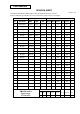
Confidential REVISION SHEET Sheet 1 of 6 The table below indicates which pages in this specification have been revised. Before reading this specification, be sure you have the correct version of each page. Revisions Design Section Sheet Rev. No. Rev. Document WRT CHK APL Sheet Sheet Rev. A Enactment N.Asai N.Asai K.Itoh I L 17 L 41 L B Change N.Asai N.Asai K.Itoh II L 18 L 42 L C Change Kawakami N.Asai N.Asai III L 19 L 43 L D Change Kawakami N.Asai K.
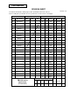
Confidential REVISION SHEET Sheet 2 of 6 The table below indicates which pages in this specification have been revised. Before reading this specification, be sure you have the correct version of each page. Revisions Design Section WRT CHK Sheet Rev. No. Rev. Document APL Sheet Rev. A Enactment 65 L 89 L App.8 L B Change 66 L 90 L App.9 L C Change 67 L 91 L App.10 L D Change 68 L 92 L App.
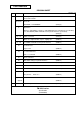
Confidential REVISION SHEET Sheet 3 of 6 REV. SHEET B CHANGED CONTENTS The major change for this revision is the addition of bidirectional parallel interface. See below for detail. all sheets Sheet title TM-U200D → TM-200D/PD II (Change) Application Applies to TM-U200D.→ Applies to TM-U200D (RS-232 serial interface specification) or to TM-U200PD (IEEE 1284 bidirectional parallel interface specification). (Change) IV ∼ VI Table of contents (Change) 6 When one original and two copies...
Confidential REVISION SHEET Sheet 4 of 6 REV. SHEET E I CHANGED CONTENTS General Description This specification ........ (Change) interface specification 8 45 - 48 F I 1.10 Reliability 1) Life ....... of 7.5 million lines. 3.3.3 DIP Switches Addition of the print head type. (Change) (Change) The applied models for this specification are changed. VI This page was left blank afle to the deletion of Appendix G. 5 1.4 Roll Paper Supply Unit Note: .....by glue ... → .....by tape or glue ... 1.
Confidential REVISION SHEET Sheet 5 of 6 REV. F SHEET 65 CHANGED CONTENTS DLE EOT n [Reference] ..... [3.5.1 Error types] is newly added. 67 ESC SP n [Description] ..... [n × (1/160)] inches → [n × 0.159 mm {1/160 inches}]. 78 ESC T n and ESC K [ n × (1/144)] inches → [ n × 0.176 mm {1/144 inches}] 85 ESC e n 48/144 inch → 8.467 mm {48/144 inches} 86 ESC r n [Notes] 91 [•This command ..... printing model] is newly added. GS V and GS V m n [Description] ... [n ×(1/144 inches)] → [n × 0.
Confidential REVISION SHEET Sheet 6 of 6 REV. SHEET J All K Nondisclosure Agreement → Confidentiality Agreement IV Table of Contents are changed due to the reason below: Section 2.3.10 (Newly added) 6.3 Exception processing (Deleted) 7,8 1.11 Applicable Standards All descriptions are changed. 36 3.2.10 Page 19 (Newly added) 37-46 3.2.11 and 3.2.20 are renumbered. 62 6.3 Exception processing (Deleted) 63 6.4 → 6.3 (renumbered) 88 ESC t n n=19 (Newly added) IV Table of Contents 3.3.
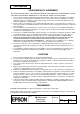
Confidential CONFIDENTIALITY AGREEMENT BY USING THIS DOCUMENT, YOU AGREE TO ABIDE BY THE TERMS OF THIS AGREEMENT. PLEASE RETURN THIS DOCUMENT IMMEDIATELY IF YOU DO NOT AGREE TO THESE TERMS. 1. This document contains confidential, proprietary information of Seiko Epson Corporation or its affiliates. You must keep such information confidential.
Confidential General Description This specification applies to the TM-U210 series.
Confidential Features This printer was developed on the basis of the hild performance/casr design concept. This printer, is a one-station printer that is light, and offers excellent reliability, printer also emphasizes the satisfichon of the user needs.
Confidential TABLE OF CONTENTS I. BASIC SPECIFICATIONS .................................................................................................................... 1 1.1 Printing Specifications ................................................................................................................... 1 1.2 Character Specifications............................................................................................................. 1 1.3 Ribbon Cassette ................................
Confidential 3.3.3 DIP switches..................................................................................................................... 47 Panel LED Indicators ................................................................................................................ 49 3.4.1 Panel LED indicators........................................................................................................ 49 3.5 Error Processing.....................................................................
Confidential ESC R n..................................................................................................................................... 78 ESC U n..................................................................................................................................... 79 ESC a n ..................................................................................................................................... 80 ESC c 3 n ........................................................
Confidential I. BASIC SPECIFICATIONS 1.1 Printing Specifications (1) Printing method Serial impact dot-matrix (2) Head wire configuration 9-pin serial configuration (3) Printing directions Bi-directional printing (logical seeking) (4) Printing speed Approx. 3.5 lps (40 column, 16 cpi) Approx. 6.4 lps (16 column, 16 cpi) (Excludes data transfer and processing time) (lps: lines per second) NOTES: 1. If the printing duty ratio is too high, the operation of the print head is stopped by the duty limit.
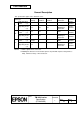
Confidential (2) Character configuration 7×9 9×9 16 × 16 (for the multilingual supporting model) Thai characters: 7 × 27 (for the multilingual supporting model) 9 × 27 (for the multilingual supporting model) (3) Character dimensions Refer to Table 1.2.1 (cpl: characters per line) (cpi: characters per inch) Table 1.2.1 Character Dimensions, Characters Per Inch, Characters Per Line Character Dot spacing Characters Characters Character configuration dimensions between per line per inch Horiz. × Vert.
Confidential 1.3 Ribbon Cassette (1) Special ribbon cassettes Model No. Color ERC-38 (P) Purple ERC-38 (B) Black ERC-38(B/R) Black/Red Ribbon life (*1) 4 million characters (with continuous printing at 25°C {77°F}) 3 million characters (with continuous printing at 25°C {77°F}) Black: 1.
Confidential Red Black 26.2 73.8 Ribbon 124.5 [Units: mm] Figure 1.3.2 External View of ERC-38 (B/R) NOTE: Malfunctions and other problems may arise if a ribbon other than the specified ribbon cassette is used. Seiko Epson does not warrant against problems arising from the use of ribbons other than the specified one. TITLE EPSON TM-U210 series Specification (STANDARD) SHEET REVISION L NO.
Confidential 1.4 Roll Paper Supply Unit (1) Supply method Drop-in method (2) End detector (a) Detection method (b) Detection position By mechanical microswitch Positioned within the paper path for roll paper; detects the near end of the roll paper (3) Near end detector (Optional) (a) Detection method By mechanical microswitch (b) Inner diameter of paper roll core: 10.5 to 12.5 mm (Refer to Appendix B for details.
Confidential Note: When one original and two copies (a total of three sheets) are used in an operating environment of 34°C {93°F} and 90% humidity, the paper roll may slightly curl. (b) Copying capability The copying capability is affected by the ambient temperature, and is guaranteed for the temperature ranges shown in the table below. Number of copies Original + two copies Original + one copy 1.
Confidential 1.9 Receive Buffer Either approximately 1KB or 40 bytes can be selected by DIP switch (for all model types except multilingual supporting model) Either 512KB or 40 bytes can be selected by DIP switch (for the multilingual supporting model). 1.10 Electrical Specifications (1) Power supply operation AC adapter included. Select one of the following five types, depending on the specifications.
Confidential Conditions of Acceptability 1) This component has been judged on the basis of the required spacing in the Standard for Information Technology equipment, Including Electrical Business Equipment, UL 1950 and CSA C22.2 No. 950, Sub-clause 2.9, which would cover the component itself if submitted for Listing. 2) This unit is intended to be supplied by a SELV circuit only. 3) The terminals and connectors have not been evaluated for field wiring.
Confidential 1.13 Environmental Specifications (1) Temperature During operation: 0 to 50°C {41° to 122°F}. (At 34°C {93°F} or higher, there are humidity restrictions; refer to Figure 1.13.1.
Confidential 1.14 Printer Installation Stance Position Install the printer horizontally. Make sure that it does not tilt more than 15°. The printer must also be installed so that it does not move or vibrate during paper cutting or the drawer kick-out operation. Fastening tape is available as an option. TITLE EPSON TM-U210 series Specification (STANDARD) SHEET REVISION L NO.
Confidential 2. CONFIGURATION 2.1 Interface Specifications 2.1.1 RS-232 Serial Interface 2.1.1.1 Specifications Data transmission: Synchronization: Handshaking: Signal levels: Baud rate: Data word length: Parity: Stop bits: Connector: Serial Asynchronous DTR/DSR or XON/XOFF control MARK = -3 to -15 V ... logic ‘1’ / OFF SPACE = +3 to +15 V ...
Confidential 2.1.1.3 Interface connector terminal assignments and signal functions Table 2.1.1 Interface Pin Assignments and Functions Pin Signal Signal Function No. Name Direction FG – Frame ground 1 2 3 4 TXD RXD Output Input Transmit data Receive data RTS Output 6 DSR Input 7 20 SG DTR – Output Same as DTR signal (same as pin 20) Indicates whether the host can receive data. SPACE indicates that the host can receive data, and MARK indicates that the host cannot receive data.
Confidential ∗1 • The period from when the remaining space in the receive buffer drops to 16 bytes until it increases to 32 bytes is called the “buffer full state.” • Data received when the remaining space in the receive buffer is zero bytes is ignored. 2.1.1.4 XON/OFF transmission timing When XON/OFF control is selected, the printer transmits XON or XOFF signals as follows. Transmit timing depends on the setting of DIP switch 1-8 Table 2.1.
Confidential 2.1.1.6 Notes on setting DIP switch 1-8 to on (1) The printer mechanism stops but does not become BUSY in the following cases: • When an error occurs. • When the printer stops printing due to a paper-end. • When paper is fed using the feed button. (2) When handshaking with the printer while using this switch setting, make sure to monitor the printer with the GS a command and the ASB function. With this switch setting, the default value of the GS a command n is 2.
Confidential Reset minimum pulse width: TRS 1 ms (minimum) • When pin 6 (DSR) is used: Figure 2.1.1 Interface Reset Signal (Pin 6) • When pin 25 (INIT) is used: Figure 2.1.2 Interface Reset Signal (Pin 25) NOTES: 1. Correct printer operation is not guaranteed unless the signals meet the above stated conditions. The above conditions must also be met when TTL signals are used to drive the DSR and INIT reset pins.
Confidential 2.1.2 IEEE 1284 Bidirectional Parallel Interface (Parallel Interface Specifications) Copyright (C) 1993 by the Institute of Electrical and Electronic Engineers, Inc. 2.1.2.
Confidential 2.1.2.
Confidential NOTES: 1. A prefix “n” to signal names refers to “L” active signals. To the host not provided with all the signal lines listed above, both-way communication fails. 2. For interfacing, signal lines shall use twisted pair cables with the return sides connected to signal ground level. 3. Interfacing conditions shall be all based on the TTL level to meet the characteristics described below. In addition, both rise time and fall time of each signal shall be 0.5µs or less. 4.
Confidential +5 V Signal Sender Characteristics Characteristics Symbol Specifications Conditions Min Max Output HIGH voltage VOH *2.4 V 5.5 V Output LOW voltage VOL - - ** Output HIGH current IOH - 0.32 mA Output LOW current IOL - ** - *IOH=0.32mA While the power is OFF VOH=2.4V While the power is OFF ** No guarantee is offered to VOL and IOL while the power is OFF. 2.1.2.
Confidential 2.1.2.7 Notes on resetting the printer through the interface The printer reset is available through the interface nInit signal (pin 31) by changing the DIP switch setting. (Refer to Table 2.1.5. DIP Switch settings for Printer Reset.) Table 2.1.5 Signal Line Pin 31 (nInt) DIP Switch Setting for Printer Reset DIP Switch Reset Condition DSW 2-8: ON TTL-LOW level input The printer reset through the nInit signal is only available with the SelectIn(1284-Active) signal at LOW.
Confidential 2.1.2.9 Reception of status from the printer through the bidirectional parallel interface In the bidirectional parallel interface specifications, the printer status transmission is available by using the both-way communication facility in the Nibble/Byte Modes in accordance with the IEEE 1284. In this case, as opposed to the RS-232 serial interface specifications, the real-time interruptions from the printer to the host are disabled, and thus, precautions must be taken to the following.
Confidential 2.2 Connectors 2.2.1 Interface connectors Refer to Section 2.1, Interface Specifications. (1) RS-232 serial interface specification 14 25 1 2 6 3 1 1 13 Interface Connector Figure 2.2.1 Drawer Kick-out Connector Power Supply Connector Serial Connector Panel Diagram (2) IEEE 1284 Parallel interface specification 2 3 Interface Connector Figure 2.2.2 Drawer Kick-out Connector 1 Power Supply Connector Parallel Connector Panel Diagram 2.2.
Confidential 2.2.3 Drawer kick-out connector (modular connector) The signal specified by the ESC p command is output to this connector. The host can confirm the input signal state by using the DLE EOT, GS a, and GS r commands. 1) Pin assignments Table 2.2.2 Drawer Kick-out Connector Pin Assignments Pin No.
Confidential 3) Drawer open/close signal FG Input signal level (connector pin 3): Figure 2.2.6 “L” = 0 V , “H” = 2 to 5 V Drawer Circuitry NOTES: 1. Two driver transistors cannot be driven simultaneously. 2. The drawer drive duty must be as shown below: On time (ON time + OFF time) ≤ 0.2 3. Be sure to use the printer power supply (connector pin 4) for the drawer power source. 4. The resistance of the drawer kick-out solenoid must not be less than that specified (24 Ω).
Confidential 3. FUNCTIONS 3.
Confidential Command ESC t ESC { GS ( A GS I GS V GS a GS r GS z 0 Valid command when the reception buffer capacity is 40 bytes *2 Name Command Classification(*1) Execution Command Setting Command { { Select character code table Turn upside-down printing mode on/off Execute test print Transmit printer ID Feed paper for cutting position Enable/disable Automatic Status Back Transmit status { { { { { { { Set on-line recovery wait time *1: There are two major classifications for comand, as follows:
Confidential 3.2 Character Code Tables 3.2.1 Page 0 (PC437: U.S.A. Standard Europe) (International character set: U.S.A.) NOTE: The actual print patterns differ from those in the above charactor code. TITLE EPSON TM-U210 series Specification (STANDARD) SHEET REVISION L NO.
Confidential 3.2.2 Page 1 (Katakana) TITLE EPSON TM-U210 series Specification (STANDARD) SHEET REVISION L NO.
Confidential 3.2.3 Page 2 (PC850: Multilingual) TITLE EPSON TM-U210 series Specification (STANDARD) SHEET REVISION L NO.
Confidential 3.2.4 Page 3 (PC860: Portuguese) TITLE EPSON TM-U210 series Specification (STANDARD) SHEET REVISION L NO.
Confidential 3.2.5 Page 4 (PC863: Canadian-French) TITLE EPSON TM-U210 series Specification (STANDARD) SHEET REVISION L NO.
Confidential 3.2.6 Page 5 (PC865: Nordic) TITLE EPSON TM-U210 series Specification (STANDARD) SHEET REVISION L NO.
Confidential 3.2.7 Page 6 (Hiragana) (Available on Japanese Kanji model) TITLE EPSON TM-U210 series Specification (STANDARD) SHEET REVISION L NO.
Confidential 3.2.8 Page 7 (One-pass printing Kanji characters) (Available on Japanese Kanji model) TITLE EPSON TM-U210 series Specification (STANDARD) SHEET REVISION L NO.
Confidential 3.2.9 Page 8 (One-pass printing Kanji characters) (Available on Japanese Kanji model) TITLE EPSON TM-U210 series Specification (STANDARD) SHEET REVISION L NO.
Confidential 3.2.10 Page 19 (PC858:Euro) TITLE EPSON TM-U210 series Specification (STANDARD) SHEET REVISION L NO.
Confidential 3.2.11 Page 20 (Thai character code 42) TITLE EPSON TM-U210 series Specification (STANDARD) SHEET REVISION L NO.
Confidential 3.2.12 Page 21 (Thai character code 11) TITLE EPSON TM-U210 series Specification (STANDARD) SHEET REVISION L NO.
Confidential 3.2.13 Page 22 (Thai character code 13) TITLE EPSON TM-U210 series Specification (STANDARD) SHEET REVISION L NO.
Confidential 3.2.14 Page 23 (Thai character code 14) TITLE EPSON TM-U210 series Specification (STANDARD) SHEET REVISION L NO.
Confidential 3.2.15 Page 24 (Thai character code 16) TITLE EPSON TM-U210 series Specification (STANDARD) SHEET REVISION L NO.
Confidential 3.2.16 Page 25 (Thai character code 17) TITLE EPSON TM-U210 series Specification (STANDARD) SHEET REVISION L NO.
Confidential 3.2.17 Page 26 (Thai character code 18) TITLE EPSON TM-U210 series Specification (STANDARD) SHEET REVISION L NO.
Confidential 3.2.18 Page 254 (space page) TITLE EPSON TM-U210 series Specification (STANDARD) SHEET REVISION L NO.
Confidential 3.2.19 Page 255 (space page) TITLE EPSON TM-U210 series Specification (STANDARD) SHEET REVISION L NO.
Confidential 3.2.20 International character sets ASCII code (Hex) Country 23 24 40 5B 5C 5D 5E 60 7B 7C 7D 7E U.S.A # $ @ [ ¥ ] ^ ` { | } ~ France # $ à ° ç § ^ ` é ù è ¨ Germany # $ § Ä Ö Ü ^ ` ä ö ü ß U.K.
Confidential 3.3 Switches and Buttons 3.3.1 Power switch The power switch (rocker switch) is on the lower right front of the printer and turns the power on or off. 3.3.2 Panel buttons FEED button [Type] Non-locking push button The ESC c 5 command enables or disables the panel button. When disabled, the FEED button will not function. However, when loading roll paper, if the paper loading wait time has been set with GS z 0, the paper FEED button can be used to feed the paper forward within the set time.
Confidential Table 3.3.2 DIP Switch 2 ON OFF Switch No.
Confidential 3.4 Panel LED Indicators 3.4.1 3.5 Panel LED indicators (1) Power supply (POWER) LED: Green ON: Power supply is stable. OFF: Power supply is not stable. (2) Paper roll near-end (PAPER OUT) LED: Red ON: Near-end or end of paper roll is detected. (*1) OFF: Adequate paper remains on the paper roll (normal condition). Blinking: Waiting for recavery to online status after automatic paper feeding. Or for restarting test printing on paper roll. *1: A near-end detector is optionally installed.
Confidential 3) Errors that cannot be recovered CPU execution error Table 3.5.3 Unrecoverable Errors Description ERROR LED blinking pattern After R/W checking, the printer does not work correctly. CPU executes Approx. 160 ms incorrect address. High voltage error Power voltage is extremely high. Impossible to recover. Low voltage error Power voltage is extremely low. Impossible to recover. Print head temperature detection circuit error Abnormality in the mechanism or circuit connection.
Confidential 3.6 Self-test (1) The printer has a self-test function that checks the following: • Control circuit functions • Printer mechanism • Print quality • Control ROM version • DIP switch settings (2) Self-test on paper roll [Starting the self-test] To start the self-test on a paper roll, hold down the FEED button and turn on the printer with the cover closed.
Confidential 3.7 Hexadecimal Dum (1) Hexadecimal dump function This function prints the data transmitted from the host in hexadecimal numbers and their corresponding characters. (2) Starting hexadecimal dumping Turn the printer power off and set DIP switch 1-2 to on to select 40 bytes for the receive buffer capacity. Then, turn on the power while pressing the FEED button. Before finishing the initialization of the printer, release the FEED button, then press the FEED button again.
Confidential 3.8 Paper Detectors The printer has the following paper detectors: • Paper roll end detector • Paper roll near-end detector (Optional) 3.8.1 Detectors and LED indicators (1) Roll paper end detector This detector is located in the roll paper path. This detector detects paper out. When the paper out is detected, the PAPER OUT LED lights. (2) Paper roll near-end detector (optional) This sensor is installed on the paper roll supply device.
Confidential 4. CASE SPECIFICATIONS 4.1 External Dimensions and Mass Model type A B D Width 160 mm {approximately 6.3”} 160 mm {approximately 6.3”} 160 mm {approximately 6.3”} External Dimensions Height 160 mm {approximately 6.3”} 150 mm {approximately 5.9”} 133 mm {approximately 5.2”} Depth 295 mm {approximately 11.6”} 248 mm {approximately 9.8”} 248 mm {approximately 9.8”} Mass Approximately 2.5 kg Approximately 2.5 kg Approximately 2.2 kg 4.2 Color Epson standard color 160 {approx.6.3”} 4.
Confidential 73 248 {approx.9.8} 337 {approx.13.3} (cover open) {approx.2.9} 160 {approx.6.3} 313{approx.12.3} (cover open) 150 {approx.5.9} 321{approx.12.6} (maximum height with cover open) [Units: mm {inch}] Figure 4.3.2 External Appearance (Type B) TITLE EPSON TM-U210 series Specification (STANDARD) SHEET REVISION L NO.
248 {approx. 9.8} Confidential 133 {approx.5.2} 160 {approx. 6.3} [Units: mm {inches}] Figure 4.3.3 External Appearance (Type D) TITLE EPSON TM-U210 series Specification (STANDARD) SHEET REVISION L NO.
Confidential 5. ACCESSORIES AND OPTIONS 5.1 Standard Accessories Exclusive ribbon cassette (ERC-38 (P) or ERC-38(B/R)) Paper roll Operator’s manual AC adapter (Refer to Table 5.1.1 for settings at shipment) Table 5.1.1 Settings at Shipment Settings at Shipment Voltage AC Adapter Model Name Japan 100 V PA-6508 North America 120 V PB-6509 Europe (Germany) 230 V PB-6510 Europe (U.K) 230 V PA-6511 Australia 240 V PA-6513 5.1.
Confidential Fuse Printer Side Connector: Hosiden TCS7960-53-2010 or equivalent The figure above shows the configuration of the AC adapter. Please handle it carefully. NOTES 1: The two AC adapters differ in external appearance and in whether they connect to connector terminal 3 of the DC cord. In the TM-U200, connector terminal 3 of the DC cord is not used. When designing the system, be sure to allow enough space to install either AC adapter. (The PB type is larger than the PA type.
Confidential 6. Commands 6.1 Command Notation XXXX [Name] The name of the command. [Format] The code sequence. [Range] Gives the allowable ranges for the arguments. [Description] Describes the command’s function. [Notes] Provides important information on setting and using the printer command, if necessary. Items marked with ∗ indicate "important notice." [Default] Gives the default values,(if any) for the command arguments. [Reference] Lists related commands.
Confidential (5) Printable area The maximum range within which printing is possible under the printer specifications. printable area for this printer is 400/160 inches. The (6) Ignore The state in which all codes, including parameters, are read in and discarded, and nothing happens. (7) Invalid The state in which the command portion of codes is read in and discarded, while the parameter portion of codes is treated as normal data. (8) Inch A unit of length. One inch is 25.4 mm.
Confidential 6.3 Command Descriptions HT [Name] Horizontal tab [Format] ASCII HT Hex 09 Decimal 10 [Description] Moves the print position to the next horizontal tab position. [Notes] • This command is valid only when the receive buffer capacity is 40 bytes (when DIP switch 1-2 is on). • This command is ignored unless the next horizontal tab position has been set. • If the next horizontal tab position is outside the printing area, the printing position shifts to "printing area width + 1.
Confidential CR [Name] Print and carriage return [Format] ASCII CR Hex 0D Decimal 13 [Description] ➀ For the serial interface model • This command prints the data in the print buffer and does not feed the paper. ➁ For the parallel interface model • When auto-line feed is enabled, this command functions in the same way as LF. When auto-line feed is disabled, this command is disregarded.
Confidential • When Auto Status Back (ASB) is enabled using the GS a command, the status transmitted by the DLE EOT command and the ASB status must be differentiated by using the table in Appendix E. • This command is effective even if the printer is not selected by set peripheral device command, ESC =. n = 1: Printer status Bit Off/On Hex 0 Off 00 1 On 02 2 Off 00 On 04 3 Off 00 On 08 4 On 10 5 Off 00 On 20 6 7 Off 00 Decimal 0 2 0 4 0 8 16 0 32 0 Function Not used. Fixed to Off. Not used. Fixed to On.
Confidential n = 3: Error status Bit Off/On Hex 0 Off 00 1 On 02 2 Off 00 On 04 3 Off 00 On 08 4 On 10 5 Off 00 On 20 6 Off 00 On 40 7 Off 00 Bit 2: Bit 6: Decimal 0 2 0 4 0 8 16 0 32 0 64 0 Function Not used. Fixed to Off. Not used. Fixed to On. No mechanical error. Mechanical error occurred. No autocutter error. Autocutter error occurs. Not used. Fixed to On. Unrecoverable error. Recoverable error. Automatic recover error. No automatic recover error. Not used. Fixed to Off.
Confidential DLE ENQ n [Name] Real-time request to printer [Format] ASCII DLE ENQ Hex 10 05 Decimal 16 5 [Range] n = 0, n = 2 [Description] The printer responds to a request from the host specified by n. n n n n = 0: Recovers to online state. n = 2: Recovers from an error after clearing the receive and print buffers. [Notes] ∗ The status is also transmitted whenever the data sequence of <10>H<05>H n = 2 is received.
Confidential ESC SP n [Name] Set right-side character spacing [Format] ASCII ESC SP Hex 1B 20 Decimal 27 32 [Range] 0 ≤ n ≤ 255 [Description] Sets the character spacing for the right side of the character to [n × 0.159 mm {1/160 inches}] . [Notes] • The right-side character spacing for double-width mode is twice the normal value.
Confidential [Notes] • When both double-height and double-width modes are selected, quadruple size characters are printed. • Underlining is added to the entire width of each character, including the space to the right of a character, but is not added to portions of lines that were skipped by means of an HT. • The underline setting by this command does not affect the Kanji character printing.
Confidential ESC & y c1 c2 [x1 d1...d(y × x1)]...[xk d1... d(y × xk)] [Name] Define user-defined characters [Format] ASCII ESC & Hex 1B 26 Decimal 27 38 [Range] y=2 32 ≤ c1 ≤c2 ≤ 126 0 ≤ x ≤ 12 (9 × 9 font) 0 ≤ x ≤ 9 (7 × 9 font) 0 ≤ d1 ... d(y × x) ≤ 255 [Description] Defines user-defined characters. y c1 c2 [x1 d1...d(y × x1)]...[xk d1... d(y × xk)] y c1 c2 [x1 d1...d(y × x1)]...[xk d1... d(y × xk)] y c1 c2 [x1 d1...d(y × x1)]...[xk d1...
Confidential • If downloaded characters equal to the number of characters that can be defined have already been downloaded, redefinition of the defined ASCII codes is possible, but definition of new ASCII codes is not possible. [Default] The internal character set [Reference] ESC %, ESC ? [Example] 7 x 9 font when the dot pattern for code 20H is defined as shown below. When the dot pattern for code 20H is defined as shown above.
Confidential ESC ∗ m nL nH d1...dk [Name] Select bit-image mode [Format] ASCII ESC ∗ Hex 1B 2A Decimal 27 42 [Range] m = 0, 1 0 ≤ nL ≤ 255 0 ≤ nH ≤ 3 0 ≤ d ≤ 255 [Description] Selects a bit-image mode using m for the number of dots specified by nL and nH m nL nH d1...dk m nL nH d1...dk m nL nH d1...dk • Divide the number of dots to be printed by 256. The interger answer is nH and the remainder is nL. Therefore, the number of dots in the horizontal direction is calculated by nL + 256 × nH.
Confidential • The relationship between the image data and the dots to be printed is as follows. ESC − n [Name] Turn underline mode on/off [Format] ASCII ESC − Hex 1B 2D Decimal 27 45 [Range] n = 0, 1, 48, 49 [Description] Turns underline mode on or off, n n n • When n = 0 or 48, underline mode is turned off. • When n = 1 or 49, underline mode is turned on. [Notes] • Underlines can be printed for all characters, but not for the space set by HT.
Confidential ESC 2 [Name] Select default line spacing [Format] ASCII ESC 2 Hex 1B 32 Decimal 27 50 [Description] Selects default (1/6-inch) line spacing. [Reference] ESC 3 ESC 3 n [Name] Set line spacing [Format] ASCII ESC 3 Hex 1B 33 Decimal 27 51 [Range] 0 ≤ n ≤ 255 [Description] Sets the line spacing to [n × 0.176 mm {1/144 inches}].
Confidential ESC = n [Name] Select device [Format] ASCII ESC = Hex 1B 3D Decimal 27 61 [Range] 1≤n≤3 [Description] Selects device to which host computer sends data, using n as follows: Bit 0 1 2 3 4 5 6 7 Off/On Off On Off On - Hex 00 01 00 02 - Decimal 0 1 0 2 - n n n Function Printer disabled. Printer enabled. Customer display disabled. Customer display enabled.
Confidential ESC ? n [Name] Cancel user-defined characters [Format] ASCII ESC ? Hex 1B 3F Decimal 27 63 [Range] 32 ≤ n ≤ 126 [Description] Cancels user-defined characters. [Notes] n n n • This command is valid only when the receive buffer capacity is 40 bytes (when DIP switch 1-2 is on). • This command cancels the pattern defined for the character code specified by n After the user-defined characters is canceled, the corresponding pattern for the internal character is printed.
Confidential ESC D n1... nk NUL [Name] Set horizontal tab positions [Format] ASCII ESC D Hex 1B 44 Decimal 27 68 [Range] 1 ≤ n ≤ 255 n1...nk n1...nk n1...nk NUL 00 0 0 ≤ k ≤ 32 [Description] Sets horizontal tab positions. • n specifies the column number (counted from the beginning of the line) for setting a horizontal tab position. • k indicates the total number of horizontal tab positions to be set.
Confidential ESC E n [Name] Turn emphasized mode on/off [Format] ASCII ESC E Hex 1B 45 Decimal 27 69 [Range] 0 ≤ n ≤ 255 [Description] Turns emphasized mode on or off. • When the LSB of n is 0, emphasized mode is turned off. • When the LSB of n is 1, emphasized mode is turned on. [Notes] • 2-pass printing is slower in emphasized mode. n n n • Only the lowest bit of n is enabled. • The printer does not emphasize bit-images. • This command and ESC ! turn on and off emphasized mode in the same way.
Confidential ESC J n [Name] Print and feed paper [Format] ASCII ESC J Hex 1B 4A Decimal 27 74 [Range] 0 ≤ n ≤ 255 [Description] Prints the data in the print buffer and feeds the paper [n × 0.176 mm {1/144 inches}] . [Notes] • n n n After printing is completed, this command sets the print starting position to the beginning of the line. • This command has no effect on the line feed amount set by the ESC 2 command or the ESC 3 command.
Confidential ESC R n [Name] Select an international character set [Format] ASCII ESC R Hex 1B 52 Decimal 27 82 [Range] 0 ≤ n ≤ 13 [Description] Selects an international character set n from the following table: n n n n Character set 0 U.S.A. 1 France 2 Germany 3 U.K.
Confidential ESC U n [Name] Turn unidirectional printing mode on/off [Format] ASCII ESC U Hex 1B 55 Decimal 27 85 [Range] 0 ≤ n ≤ 255 [Description] Turns unidirectional printing mode on or off n n n When the LSB of n is 0, turn off unidirectional printing mode. (Turn bidirectional printing mode on.) When the LSB of n is 1, turn on unidirectional printing mode and turn on bidirectional printing mode. [Notes] • Only the lowest bit of n is enabled.
Confidential ESC a n [Name] Select justification [Format] ASCII ESC a Hex 1B 61 Decimal 27 97 [Range] 0 ≤ n ≤ 2, 48 ≤ n ≤ 50 [Description] Aligns all the data in one line to the specified position. n selects the type of justification as follows: n 0, 48 1,49 2, 50 n n n Justification Left justification Centering Right justification [Notes] • The command is enabled only when input at the beginning of the line.
Confidential ESC c 3 n [Name] Select paper detector(s) to output paper end signals [Format] ASCII ESC c Hex 1B 63 Decimal 27 99 [Range] 0 ≤ n ≤ 255 [Description] Selects paper detector(s) to output paper end signals, using n as follows: Bit 0 Off/On Off On Off On Off On Off On - 1 2 3 4 5 6 7 [Notes] Hex 00 01 00 02 00 04 00 08 - 3 33 51 n n n Decimal 0 1 0 2 0 4 0 8 - Function Paper roll near end sensor disabled. Paper roll near end sensor enabled. Paper roll near end sensor disabled.
Confidential ESC c 4 n [Name] Select paper sensor(s) to stop printing [Format] ASCll ESC c Hex 18 63 Decimal 27 99 [Range] 0 ≤ n ≤ 255 [Description] Selects the paper sensor(s) to use to stop printing when a paper-end is detected, using n as follows : Bit Off/On Hex 4 34 52 n n n Decima Function l 0 Off 00 0 Paper roll near-end sensor disabled. On 01 1 Paper roll near-end sensor enabled. Off 00 0 Paper roll near-end sensor disabled. On 02 2 Paper roll near-end sensor enabled.
Confidential ESC c 5 n [Name] Enable/disable panel buttons [Format] ASCII ESC c Hex 1B 63 Decimal 27 99 [Range] 0 ≤ n ≤ 255 [Description] Enables or disables the panel buttons. 5 35 53 n n n • When the LSB of n is 0, the panel buttons are enabled. • When the LSB of n is 1, the panel buttons are disabled. [Notes] • Only the least significant bit of n is valid. • When the panel buttons are disabled, no buttons on the panel are usable. If "disabled" is set, the paper FEED button no longer functions.
Confidential ESC e n [Name] Print and reverse feed n lines [Format] ASCII ESC e n Hex 1B 65 n Decimal 27 101 n [Range] 0≤n≤2 [Description] Prints the data in the print buffer and feeds n lines in the reverse direction. [Notes] • This command must not be issued continuously more than two times. • Reverse direction paper feeding causes the following problems: 1) Paper feed pitch is incorrect. 2) Printer noise is louder than normal. 3) The paper may rub against the ribbon and become dirty.
Confidential ESC r n [Name] Select print color [Format] ASCII ESC r n Hex 1B 72 n Decimal 27 114 n [Range] n = 0, 1, 48, 49 [Description] Selects the print color. n [Notes] Selected color 0, 48 Black 1, 49 Red • Valid only when input at the beginning of a line. • This command is effective only for the two-color printing model. [Default] n=0 TITLE EPSON TM-U210 series Specification (STANDARD) SHEET REVISION L NO.
Confidential ESC t n [Name] Select character code table [Format] ASCII ESC t n Hex 1B 74 n Decimal 27 116 n [Range] 0 ≤ n ≤ 8, [Description] Selects a page n from the character code table. n 0 1 2 3 4 5 6 7 8 19 20 (*) 21 (*) 22 (*) 23 (*) 24 (*) 25 (*) 26 (*) 254 255 19 ≤ n ≤ 26, n = 254, 255 Page PC437 [U.S.A.
Confidential ESC { n [Name] Turns on/off upside-down printing mode [Format] ASCII ESC { n Hex 1B 7B n Decimal 27 123 n [Range] 0 ≤ n ≤ 255 [Description] Turns upside-down printing mode on or off. • When the LSB of n is 0, upside-down printing mode is turned off. • When the LSB of n is 1, upside-down printing mode is turned on. [Notes] • Only the lowest bit of n is effective. • This command is enabled only when input at the beginning of a line.
Confidential GS ( A pL pH n m [Name] Execute test print [Format] ASCII GS Hex 1D Decimal 29 [Range] (pL+(pH×256))=2 (where pL=2, pH=0) 0 ≤ n ≤ 2, 48 ≤ n ≤ 50 1 ≤ m ≤ 3, 49 ≤ m ≤ 51 [Description] • Executes a test print with a specified test pattern on the specified paper. ( 28 40 A 41 65 pL pL pL pH pH pH n n n m m m • pL and pH specifies the number of the parameter such as n, m to (pL + (pH × 256)) bytes. n specifies the paper to be tested.
Confidential GS I n [Name] Transmit printer ID [Format] ASCII GS Hex 1D Decimal 29 [Range] 1 ≤ n ≤ 3, 49 ≤ n ≤ 51, 65 ≤ n ≤ 69 [Function] Transmits the printer ID specified by n as follows: n Printer ID Specification ID (hexadecimal) 1, 49 Printer model ID TM-U200 series 0D 2, 50 Type ID See table below. 3, 51 ROM version ID ROM version 65 Firmware version Depends on firmware version. 66 Manufacturer EPSON 67 Printer name TM - U200 68 Serial number Depends on serial number.
Confidential • When the printer ID transmission is specified with (65 ≤ n ≤ 69), the following contents are transmitted: Header: Hexadecimal = 5FH / Decimal = 95 (1 byte) Data: Printer information NUL: Hexadecimal = 00H / Decimal = 0 (1 byte) After the data is ready to be transmitted, the printer executes the following process. ➀ Changes READY to BUSY. nothing. If it is already BUSY, the printer changes ➁ Transmits [Header + Data + NUL]. ➂ Executes BUSY to READY. printer changes nothing.
Confidential GS a n [Name] Enable/Disable Automatic Status Back [Format] ASCII GS Hex 1D Decimal 29 [Range] 0 ≤ n ≤ 255 a 61 97 n n n [Description] Bit 0 1 2 3 4 5 6 7 [Notes] Enables or disables ASB and specifies the status items to include, using n as follows: Off/On Hex Decimal Status for ASB Off 00 0 Drawer kick-out connector pin 3 status disabled. On 01 1 Drawer kick-out connector pin 3 status enabled. Off 00 0 On-line/off-line disabled.
Confidential First byte (printer information) Bit Off/On Hex Decimal 0 Off 00 0 1 Off 00 0 2 Off 00 0 On 04 4 3 Off 00 0 On 08 8 4 On 10 16 5 6 Off 00 0 On 40 64 7 Off 00 0 Second byte (printer information) Bit Off/On Hex Decimal 0 Off 00 0 On 01 1 1 2 Off 00 0 On 04 4 3 Off 00 0 On 08 8 4 Off 00 0 5 Off 00 0 On 20 32 6 Off 00 0 7 On 40 64 Off 00 0 Status for ASB Not used. Fixed to Off. Not used. Fixed to Off. Drawer kick-out connector pin 3 is LOW Drawer kick-out connector pin 3 is HIGH. On-line.
Confidential Fourth byte (paper sensor information) Bit Off/On Hex Decimal Status for ASB 0 Undefined. 1 Undefined. 2 Undefined. 3 Undefined. 4 Off 00 0 Not used. Fixed to Off. 5 Undefined. 6 Undefined. 7 Off 00 0 Not used. Fixed to Off. [Default] n = 0 when DIP SW 1-8 is off, n = 2 when DIP SW 1-8 is on. [Reference] DLE EOT, GS r, 3.5.
Confidential Paper sensor status (n = 1,49) Bit Off/On Hex Decimal 0,1 Off 00 0 On (03) (3) 2,3 Off 00 0 On 0C 12 4 Off 00 0 5 6 7 Off 00 0 Status for ASB Paper near-end sensor: paper present. Paper near-end sensor: paper near end. Paper end sensor: paper present. Paper end sensor: no paper present. Not used. Fixed to Off. Undefined. Undefined. Not used. Fixed to Off.
Confidential GS z 0 t1 t2 [Name] Setting of online recovery wait time [Format] ASCII GS Hex 1D Decimal 29 z 7A 122 0 30 48 t1 t1 t1 t2 t2 t2 [Range] 0 ≤ t1 ≤ 255 0 ≤ t2 ≤ 255 [Function] Sets the paper loading wait time (from paper insertion to recovery confirmation state) to approximately (t1 × 500 ms) and the recovery confirmation time (from end of the paper loading wait time to online recovery) to approximately (t2 × 500 ms).
Confidential • Approximately (t2 × 500 ms) after the end of the paper loading wait time, the printer enters the online state. This interval is the recovery confirmation time. While the printer is in the recovery confirmation state, the PAPER OUT LED flashes. In the recovery confirmation state, it is possible to re-enter the online state by executing DLE ENQ 0, by allowing the recovery confirmation time to elapse, or by pressing the paper FEED button.
Confidential FS ! n [Name] Set print mode(s) for Kanji characters [Format] ASCII FS Hex 1C Decimal 28 [Range] 0 ≤ n ≤ 255 [Description] Sets the print mode for Kanji characters, using n as follows: Bit 0 1 2 3 4 5 6 7 Off/On Off On Off On Off On Hex 00 04 00 08 00 80 ! 21 33 Decimal 0 4 0 8 0 128 n n n Status for ASB Undefined. Undefined. Double width mode disabled. Double width mode enabled. Double height mode disabled. Double height mode enabled. Undefined. Undefined. Undefined.
Confidential FS & [Name] Select Kanji character mode [Format] ASCII FS Hex 1C Decimal 28 [Description] Selects Kanji character mode. [Notes] For Japanese Kanji supporting model: • This command is effective only when the JIS code system is selected. • When Kanji character mode is selected, the printer processes each two-byte sequence as a Kanji character code. • Kanji codes are processed in the order of the first byte and second byte. • Kanji character mode is not selected when the power is turned on.
Confidential FS . [Name] Cancel Kanji character mode [Format] ASCII FS Hex 1C Decimal 28 [Description] Cancels Kanji character mode. [Notes] For Japanese Kanji supporting model: • This command is effective only when the JIS code system is selected. • When Kanji character mode is not selected, all character codes are processed one byte at a time as ASCII code. • Kanji character mode is not selected when the power is turned on. .
Confidential • The d is the dot data for the characters. The amount of data defined by d is 32 bytes, which consists of 2 bytes for vertically × 16 dots. • When the user-defined characters are defined, it is possible to redefine the defined Kanji character codes but not to define new Kanji character codes. • An example of the dot data for characters is shown below.
Confidential FS ? c1 c2 [Name] Chancel user-defined Kanji characters [Format] ASCII FS Hex 1C Decimal 28 [Range] c1 and c2 indicate character codes for the defined characters. The range of values for c1 and c2 differ depending on the character code system used.
Confidential FS S n1 n2 [Name] Set left- and right-side Kanji character spacing [Format] ASCII FS Hex 1C Decimal 28 [Range] 0 ≤ n1 ≤ 32 0 ≤ n2 ≤ 32 [Description] Sets left- and right-side Kanji character spacing n1 and n2, respectively. [Notes] S 53 83 n1 n1 n1 n2 n2 n2 • This command is valid only for the Japanese Kanji model, Chinese Kanji model, and Taiwanese Kanji model. • When double-width mode is set, the left- and right-side character spacing is twice the normal value.
Confidential 6.4 Ignored Commands The serial interface model ignores the following commands: ESC c 3 n ESC c 6 n The parallel interface model ignores the following commands: ESC c 6 n TITLE EPSON TM-U210 series Specification (STANDARD) SHEET REVISION L NO. NEXT App.
Confidential APPENDIX A: MISCELLANEOUS NOTES 1) Print duty • When printing exceeds the allowable print duty cycle, the printer automatically detects the print head temperature rise, stops logic-seeking, and enters full-column print head movement operation. This stops the temperature rise by lowering print duty. If the print head temperature continues to rise, the printer stops the print head. In this case, the user should be aware that the printing speed may slow significantly.
Confidential 15-line printing Cut (Type B only) 10-line feeding (repeats) Figure A-1 Continuous Printing Test Pattern (Using the ERC-38(P)/(B)) TITLE EPSON TM-U210 series Specification (STANDARD) SHEET REVISION L NO. NEXT App.3 SHEET App.
Confidential Figure A-2 Continuous Printing Test Pattern (Using the ERC-38(B/R)) TITLE EPSON TM-U210 series Specification (STANDARD) SHEET REVISION L NO. NEXT App.4 SHEET App.
Confidential 5) Manual operation of the autocutter In a paper jam, the printer may be stopped with the autocutter blade not in its normal position. In such cases, insert the screwdriver into the hole at the right side of the autocutter, as shown in Figure A-3, and turn the gear inside the cutter unit to move the cutter blade to its normal position. 6) Other note Because this printer uses plated steel, the cutting edges may be subject to rust.
Confidential APPENDIX B: INSTALLING THE NEAR-END DETECTOR AND ADJUSTING THE AMOUNT OF ROLL PAPER REMAINING The near-end detector is mounted in place on the printer case by using the mounting screw provided. Because the amount of paper remaining on a roll differs according to the inner and outer diameters of the core of the roll, the spacer provided can be used to adjust the amount remaining within the range indicated below.
Confidential APPENDIX C: NOTES ON CHARACTER PRINTING Applied for the user-defined characters and the following characters. Font Page Character code 7×9 0 H, H 9×9 1 H, H 9×9 0 H 1) The printer deletes the right-most dots of a character during double-width mode, if another character follows.
Confidential Example: If the following codes are transmitted, some dots are not printed. (Graphic character H + “H” double-height enlarged) PRINT #1, CHR$ (&HB2) ; PRINT #1, CHR$ (&H1B);”!”; CHR$ (&H11); PRINT #1, “H”; CHR$ ($HA) ; When the data is buffered in the print buffer Half dot dots are deleted because of the next character and not printed. Printing result (unidirectional printing) dots are not printed. To avoid this, program the software as follows.
Confidential APPENDIX D: 1) NOTES ON USING THE DRAWER KICK-OUT CONNECTOR Drawer specifications (see Section 2.2.3, Drawer kick-out connector) Drawer specifications differ significantly depending on manufacturer and model number. Make sure that the specifications of the drawer used meet the following conditions when connected to the drawer kick-out connector. These conditions also apply to any equipment (other than a drawer) that is connected to the drawer kick-out connector.
Confidential The drive signal waveform generated when the drawer is driven according to the above conditions is shown in Figure D-1. ON OFF t1 × 2 ms t2 ≥ (t1 × 4) x 2 ms Figure D-1 Drawer Drive Signal Waveform (Formulas D-1 and D-2) The ON time depends on the specifications of the drawer used. Be sure to check the drawer specifications and set a suitable time. To use a drawer that does not meet the conditions of Formulas D-1 and D-2, see the following section.
Confidential An example program in which the drawer connected to drive signal 1 is driven with an ON time of 200 ms is shown below. PRINT #1, CHR$(&H1B);”p” ;CHR$(0);CHR$(100);CHR$(250); GOSUB *WAIT300MS ON time 200 ms OFF time 500 ms *WAIT300MS 300 [ms] wait routine (*1) RETURN *1 Corresponds to α of Formula D-3. Set the value so that it satisfies Formula D-3 (or include an internal processing time that is equal to or longer than this wait routine).
Confidential APPENDIX E: TRANSMISSION STATUS IDENTIFICATION The values of specific bits are fixed in the status information transmitted by the printer, so that the status bytes of commands can be identified. The user can therefore confirm the command to which the status belongs, as shown in the following table. When using Auto Status Back (ASB), however, process the consecutive three-byte code (except for XOFF) as ASB data after confirming the first byte of the ASB.