Confidential developer’s guide TM-U230 Copied Date , , Copied by EPSON English 401347601
Confidential CONFIDENTIALITY AGREEMENT BY USING THIS DOCUMENT, YOU AGREE TO ABIDE BY THE TERMS OF THIS AGREEMENT. PLEASE RETURN THIS DOCUMENT IMMEDIATELY IF YOU DO NOT AGREE TO THESE TERMS. 1. This document contains confidential, proprietary information of Seiko Epson Corporation or its affiliates. You must keep such information confidential.
TM-U230 Developer’s Guide Confidential Revision Information Revision Page Altered Items and Contents Rev. A All Rev. B 1-6 Ethernet interface specification is added. 1-18~1-20 Ethernet interface specification is added. 2-2~2-4 Description of Waterproof is added. 3-1,3-3 The internal buzzer specification is added. 4-7~4-10 Description of DirectIO in OPOS is aded AppendixC Newly added.
Confidential Key to Symbols The following symbols are used in the documentation for this product. See the specific warnings and cautions at appropriate points throughout this guide. WARNING: Warnings must be followed carefully to avoid serious bodily injury. CAUTION: Cautions must be observed to avoid minor injury to yourself, damage to your equipment, or loss of data. Note: Notes have important information and useful tips on the operation of the product.
Confidential TM-U230 Developer’s Guide • Do not modify the power cord. • Do not place heavy objects on the power cord. • Do not bend, twist, or pull the power cord excessively. • Do not route the power cord near heaters. • Remove any dirt or dust from the power plug before plugging it in. • Be sure to fully insert the power plug. CAUTION: ❏ All cables are to be connected only as described in the manual. Incorrect connection could cause damage or a fire hazard.
Confidential Moduler Connector Use the moduler connector specifically designed for the cash drawer for this product. Do not connect a telephone line to the drawer kick-out connector. About This Guide This guide is intended to provide all information necessary for system planning, design, installation and application of the TM-U230 for designers and developers of POS systems.
Developer’s Guide Confidential developer’s guide TM-U230 Revision Information . . . . . . . . . . . . . . . . . . . . . . . . . . . . . . . . . . . . . . . . . . . . . . . . . . Key to Symbols . . . . . . . . . . . . . . . . . . . . . . . . . . . . . . . . . . . . . . . . . . . . . . . . . . . . . . . Safety Precautions . . . . . . . . . . . . . . . . . . . . . . . . . . . . . . . . . . . . . . . . . . . . . . . . . . . . .
Confidential GS V (Function C) . . . . . . . . . . . . . . . . . . . . . . . . . . . . . . . . . . . . . . . . . . . . . . . . . . Notes on Using GS V Function C . . . . . . . . . . . . . . . . . . . . . . . . . . . . . . . . . . . . . The usage of DirectIO in OPOS . . . . . . . . . . . . . . . . . . . . . . . . . . . . . . . . . . . . . . Contorol of The Buzzer . . . . . . . . . . . . . . . . . . . . . . . . . . . . . . . . . . . . . . . . . . . . .
Confidential TM-U230 Developer’s Guide Chapter 1 Installation Installation and Positioning of TM-U230 Precautions in Handling the Fine Coating Case (only for Fine Coating Case model) This printer is housed in a plastic case (*) with a fine coating; simple cleaning is enough to enable dirt to come off easily so that the exterior of the printer remains in good condition. Like plastic cases, handle the fine coating with care as described below.
Confidential External Dimensions See the External Appearance section in Appendix A. Vertical installation Horizontal installation Desk installation ❏ Wall mounting • Use the optional wall mounting bracket (Model Name: WH-10) when the printer is to be wall mounted. • When the printer is wall mounted, adjust the N.E. detector in the same way as for vertical installation. • The power supply box can be attached below the printer if necessary.
Confidential TM-U230 Developer’s Guide Dip Switch Settings Make DIP switch settings according to the following procedures. 1. Remove the circuit board plate. circuit board plate 2. Set the DIP switches.
Confidential Serial Interface DIP Switch 1 Switch No. Function On Off Default 1 Data receive error Ignored Print "?" Off 2 Receive buffer capacity 1KB 16KB Off 3 Handshaking XON/XOFF DTR/DSR Off 4 Word length 7 bit 8 bit Off 5 Parity check Yes No Off 6 Parity selection Even Odd Off 7 Baud rate selection 4800 bps 9600 bps Off 8 BUSY condition Receive buffer-full Offline Receive buffer-full Off DIP Switch 2 Switch No.
TM-U230 Developer’s Guide Confidential Parallel Interface DIP Switch 1 Switch No. Function On Off Default 1 Auto line feed Enabled Disabled Off 2 Receive buffer 1KB 16KB Off 3-7 Undefined -- -- Off 8 Busy condition Receive buffer-full Offline Receive buffer-full Off DIP Switch 2 Switch No.
Confidential Ethernet Interface DIP Switch 1 Switch No. Function On Off Default 1 Auto line feed Enabled Disabled Off 2 Receive buffer 1KB 16KB Off 3-7 Undefined -- -- Off 8 Busy condition Receive buffer-full Offline Receive buffer-full Off DIP Switch 2 Switch No.
Confidential TM-U230 Developer’s Guide Settings for Horizontal Installation Perform the following procedures when the printer is to be used in a horizontal installation. Changing the Location of the Rubber Feet Remove the rubber feet from the bottom of the printer and attach them to the back of the printer.
Confidential Changing the Orientation of Near End Sensor Perform the following procedures to change the orientation of the near end sensor. 1. Place the printer horizontally and open the roll paper cover. 2. Use a coin to loosen the near end adjustment screw. 3. Turn the protrusion on the near end holder to change the position of the near end lever. 4. Tighten the near end adjustment screw, check that the near end sensor lever operates normally and close roll paper cover.
TM-U230 Developer’s Guide Confidential Attaching Switch Panel for Horizontal Installation 1. Clean the switch panel attached to roll paper cover. Note: Do not touch the switch panel surface after cleaning. Touching this surface may lower the strength of the adhesive. 2. Remove the seal covering the adhesive surface of the switch panel for horizontal installation. Note: Do not touch the adhesive surface of the switch panel for horizontal installation.
Confidential Attaching the Power Supply Box (only for models with exclusive power supply unit) The location of the power supply box varies with the method of installation. WARNING: Use only AC adapter designated by EPSON. Using a non-standard power supply may cause a fire or shock hazard. When you are using an EPSON AC power supply or the equivalent, immediately turn off the printer and disconnect the power plug when you notice an abnormality.
TM-U230 Developer’s Guide Confidential 2. Put on the lower adapter cover with the cable through the notch in the lid and tighten the screws. In doing so, pull out the DC power supply cable from the DC power supply cable exit in the lower adapter cover so that around 15 cm of the cable protrudes from the cover. 3. Secure the covers with the screws packed with the printer (C.P.T-B Screw, 3 × 12, F/Zn).
Confidential 3. Attach the power supply box to the rear of the printer, aligning the box inside the rubber pads and secure with two screws packed with the printer (C.P.T-B Screw, 3 × 14, F/Ni). Holes 2 Holes 1 Rubber pads Screws Horizontal Installation and Wall Mounting 1. Check that the printer POWER switch is off and that the power supply cord of the AC adapter is not plugged into the wall outlet. 2. Connect DC power supply cable of the AC adapter to the DC connector on the printer.
Confidential TM-U230 Developer’s Guide 3. Attach the power supply box to the bottom of the printer and secure with two screws packed with the printer(C.P.T-B Screw, 3 × 14, F/Ni). Screws Attaching the power supply box for horizontal installation and wall mounting Wall Mounting An optional wall mounting bracket (Model Name: WH-10) is required to wall mount the printer.
Confidential Installing the wall mount CAUTION: The weight of the printer is listed in the table below. Use screws that are long enough to properly support the weight of the printer and that suit the type of wall you attach the mount to. It is recommended that you use screws with a 4 mm diameter. Secure the mount to the wall using all the 10 screw holes. Table 1-1 Weight of printer and accessories Weight TM-U230 printer AC adapter Power supply box Approx. 3.5 kg TM-U230 printer Approx.
TM-U230 Developer’s Guide Confidential Attaching the hangers Note: ❏ There are holes for 4 screws in the hangers (The number of the type of screw to be used is stamped on the hanger). Use the correct screw holes. ❏ In attaching the hangers to the printer, use the 4 screws supplied with the WH-10 wall mounting bracket. 1. Place the hangers on the printer (one at the center and the other at the bottom of the printer). 2. Use the screw holes in the printer marked "2" for the top hanger.
Confidential Attaching the printer to the wall CAUTION: Check again that the wall mounting bracket is properly secured to the wall before attaching the printer. 1. Insert the hangers in the groove of the wall mounting bracket. Attaching the printer to a wall Connecting a Host PC Turn off both the printer and the computer before making any cable connections. Note: Be sure that cables go through the holes numbered 1 in the illlustration on page 1-10.
TM-U230 Developer’s Guide Confidential Note: Your printer has inch-type hexagonal lock screws installed. If your interface cable requires millimeter-type screws, replace the inch-type screws with the enclosed millimeter-type screws using a hex screwdriver (5 mm). Inch-type screw is marked with a line Millimeter screw Inch screw Inch screw and millimeter screw 3. If your interface connector has a grounding wire, attach it to the printer using the screw labeled FG. 4.
Confidential Note: Passing the USB cable through the wire locking saddle as shown in the figure will keep the connection from coming loose. USB upstream connector UB-BOARD Locking wire saddle USB cable DM connector USB downstream connector (USB HUB: only for UB-U01) Attaching the locking wire saddle 3. Connect the USB cable from the host PC to the USB upstream connector. 4. A total of 2 USB devices can be connected to the USB downstream connector to a printer equipped with UB-U01.
TM-U230 Developer’s Guide Confidential Names of parts Ethernet interface terms are given below. 10 BASE-T Ethernet interface connector LED (green) LED (red) Do not press the LEDs. Switch Holding down this switch when the printer is powered up returns all settings to their default values. Names of parts Ethernet test switch The Ethernet test switch has the following functions.
Confidential Ethernet LEDs The operating status of the Ethernet interface is indicated by the combined status of the two Ethernet LEDs (redx1 and greenx1). No.
TM-U230 Developer’s Guide Confidential Drawer Kick-Out Connector (Marked DK) CAUTION: Connect a drawer that matches the printer specifications. Using an improper drawer may damage the printer as well as the drawer. Do not connect a telephone line to the drawer kick-out connector (marked DK). Such a connection may damage both the printer and the telephone lines. Note: Be sure that cables go through the holes numbered 1 in the illlustration on page 1-10.
Confidential 1-22 Installation
Confidential TM-U230 Developer’s Guide Chapter 2 Handling Important Safety Information WARNING: ❏ Turn off the power switch immediately and unplug the power cord from the electrical outlet if the TM-U230 produces smoke, a strange odor, or unusual noise. Continued use may lead to fire or electric shock. ❏ Do not modify the printer or perform any disassembly operation not described in this manual. Doing so could result in a fire or shock hazard. ❏ Use only the designated power supply.
Confidential CAUTION: ❏ All cables are to be connected only as described in the manual. Incorrect connection could cause damage or a fire hazard. ❏ Be sure to set this product on a firm, stable, horizontal surface. The product may break or cause injury if it falls. ❏ Do not install the printer in extremely humid or dusty locations. Operation under such conditions could damage the printer or cause a fire or shock hazard. ❏ Do not stand on the printer or place heavy objects on it.
Confidential TM-U230 Developer’s Guide IP The ability of an enclosure to keep out dirt and water is defined in IEC 529. When an enclosure protects the equipment from water and particles of dirt, it also protects people from any potential hazard inside the equipment. The degree of protection is designated by the letters "IP" followed by two digits such as "IP01" or "IP34." The first digit indicates the degree that the equipment is protected from solid foreign objects.
Confidential Example: When the IP code of a product is IP32, the first digit means that the product has protection from tools and thin wires with a diameter more than 2.5 mm and protection from solid foreign objects with a diameter greater than 2.5 mm. The second digit means that the product is protected from water coming from an angle up to 15° from vertical. The test for keeping out water coming from an angle up to 15° from vertical is executed under the following conditions.
Confidential TM-U230 Developer’s Guide Replacing roll paper Use the designated type of roll paper. (See Appendix A for information on roll paper specifications.) 1. Be sure that the power is turned on. 2. Open the roll paper cover. 3. Remove the roll paper and cut the paper along the dotted line in the figure below. Cut Roll paper cover PAPER FEED button Figure 2-2 Cutting roll paper 4. Press the PAPER FEED button to remove the cut paper. 5.
Confidential Note: If the cutter cover is opened, the printer is offline and paper will not be fed automatically. Be sure to close the cutter cover. paper insert slot Figure 2-4 Loading roll paper 8. Close the roll paper cover. 9. When the PAPER OUT LED starts to flash, press the PAPER FEED button. The printer is online when the PAPER OUT LED stops flashing. Note: The printer is offline as long as the LED is flashing.
Confidential TM-U230 Developer’s Guide Replacing the ribbon cassette Use the EPSON ERC-38 ribbon cassette. 1. Open the roll paper cover. 2. Open the cutter cover. 3. Raise the autocutter lock lever and open the autocutter. Be sure that the autocutter is locked. Lock lever Figure 2-5 Autocutter lock lever 4. Take the ribbon cassette out of the printer. 5. Turn the knob on the new ribbon cassette in the direction indicted by the arrow on the cassette to remove any slack.
Confidential 6. Insert the ribbon between the print head and the platen, as shown in the figure below, and press it in until it clicks into place. 7. Turn the ribbon cassette knob 5 to 6 times in the direction of the arrow to remove any slack in the ribbon. Note: Make sure that the ribbon is inserted between the print head and the platen and that there are no creases or folds in the ribbon.
Confidential TM-U230 Developer’s Guide Removing paper jams Paper jams in the vicinity of the print head 1. Turn off the power and open the roll paper cover. 2. Take out the roll paper and cut the paper along the dotted line in the figure below. Cut Roll paper cover Figure 2-8 Cutting roll paper 3. Open the cutter cover. 4. Raise the autocutter lock lever and open the autocutter. 5. If possible, pull the jammed paper in the paper exit direction to remove it.
Confidential Figure 2-9 Removing jammed paper CAUTION: Do not remove jammed paper by pulling it against paper feed direction. 6. Take the ribbon cassette out of the printer. 7. Loosen the screw that secures the print head cover. Loosen the screw until it tilts. 8. Remove the print head cover. CAUTION: The print head becomes hot during printing. Perform this procedure when the print head has become cool.
Confidential TM-U230 Developer’s Guide Figure 2-10 Removing the print head cover 9. Remove the jammed paper. CAUTION: Do not remove jammed paper by pulling it against paper feed direction. 10. Perform Steps 7 and 8 above in the opposite order to install the print head cover and secure it with the screw. CAUTION: Be sure to properly secure the cover with the screw. 11. Install the ribbon cassette in the printer.
Confidential Paper jam in the auto cutter When the autocutter blade is visible through the slit, a paper jam may have occurred in the auto cutter. Insert a screwdriver in the hole on the side of the autocutter to turn the gear and return the blade to a position where it cannot be seen from the slit (indicated by the bold dotted line in Figure 2-11).
Confidential TM-U230 Developer’s Guide Installing the power button cover The power button cover is provided to prevent someone from pressing the power button inadvertently. Install the cover over the printer POWER button as shown in the figure below. When a power button cover has been installed, insert a ballpoint pen or the like in the holes provided to turn the printer on and off.
Confidential 2-14 Handling
Confidential TM-U230 Developer’s Guide Chapter 3 Compatibility This Chapter describes features that are different between the TM-U230 and TM-U210 Series printers. Internal Buzzer The TM-U230 have the internal buzzer and changing the DIP Switch 2-8 setting enables/ disables the internal buzzer. Switch No. On Off Defaut 2-8 Internal buzzer Disabled Internal buzzer Enabled Off Internal buzzer noise level: Approx.
Confidential Condition Paper end DIP Switch 2-5 (PAPER OUT LED) DIP Switch 2-8 (Internal buzzer) Blinking pattern of PAPER OUT LED and buzzer pattern Off (LED is On) Off (Enabled) LED is On Buzzer sounds continuously On (Disabled) LED is On No buzzer sound On (Blinking) Off (Enabled) LED blinking pattern Approx. 640 ms Buzzer sound pattern Approx. 640 ms On (Disabled) LED blinking pattern Approx.
Confidential TM-U230 Developer’s Guide Replacing the paper roll stops the buzzer sound and turns off the PAPER OUT LED. Also pressing the FEED button stops the buzzer sound and turns off the PAPER OUT LED. Be sure that the PAPER OUT LED goes off when the buzzer sounds is stopped.
Confidential For the TM-U210 series printers, when DIP switch 1-2 is off, the following commands cannot be used; however the TM-U230 can use them.
TM-U230 Developer’s Guide Confidential Chapter 4 Programming Samples Saving Space for Receipt Printing TM-U230 has GS V function C, which can save space for receipt printing. Executes a paper cut automatically when the current position reaches the autocutter position. The details of this function are described below, comparing GS V function C with GS V function B. ❏ GS V function C Executes a partial cut (one point left uncut) ❏ GS V function B Feeds paper for cutting position + [n × 0.
Confidential 2. After printing Receipt 1, the application executes GS V function B. The printer feeds paper so that the printing on Receipt 1 exceeds the autocutter position and cuts the paper. For the next printing, there will be space between the positions of the autocutter and the print head.
TM-U230 Developer’s Guide Confidential Assumed A/C position 111111111111111 222222222222222 333333333333333 444444444444444 (Execute GS V 98 0) Assumed head position Printing direction 2. After printing the last line of Receipt 1, the application executes GS V function C. Program Example PRINT #1, “333333333333333”; CHR$(&HA); PRINT #1, “444444444444444”; CHR$(&HA); PRINT #1,CHR$(&H1D);”V”;CHR&(98);CHR&(0 The parameter “0” of GS V 98 0 indicates paper feed amount executed right before the paper cut.
Confidential 111111111111111 222222222222222 333333333333333 444444444444444 Cutting range Executing a cut Assumed A/C position 55555555555555 66666666666666 77777777777777 88888888888888 99999999999999 11111111111111 Printing direction 4. When the cutting range of Receipt 1 reaches the autocutter position while printing Receipt 2, the printer cuts the paper. Assumed head position Printing direction 5. When printing the last line of Receipt 2, the application executes GS V function C.
TM-U230 Developer’s Guide Confidential 6. The application starts printing Receipt 3. When the cutting range of Receipt 2 reaches the autocutter position while printing Receipt 3, the printer cuts the paper.
Confidential Here is an example when executing the following steps. 1. Print receipt A 2. Execute GS V 98 0 3. Print receipt B 4. Execute GS V 98 0 5. Print receipt C 6. Execute GS V 98 0 If the cutting ranges designated in step 4 and 5 have not reached the autocutter position, Receipt B and C will not be cut. Even if they have reached the autocutter position and have been cut, the receipts do not reach the paper exit.
Confidential TM-U230 Developer’s Guide The usage of DirectIO in OPOS This Chapter describes the programming samples of DirectIO in OPOS. Executes a paper cut automatically when the current position reaches the autocutter position. Executes a paper cut after feeding for 4 + pData ∗ 0.176 [mm]. The value of the pData is 0 in the following example. (the available range of pData is 0 - 255) This function is canceled when the FEED button is pressed or a command that results printer reset is executed.
Confidential Contorol of The Buzzer TM-U230 has ESC(A command, which can control the internal buzzer. ESC(A command is supported by the Firmware version 1.02 and above. You can confirm the Firmware version by the following procedure. 1. Hold on the FEED button and turn on the printer with the paper roll cover opened. 2. Printer then prints the current printer status(Control ROM version, DIP switch settings) on a roll paper.
TM-U230 Developer’s Guide Confidential Be sure to consider the BinaryConversion property when transmit the data over 80h. Chr(&H1B)+"(" + "A" + Chr(&H5) + Chr(&H0) + Chr(&H61) + Chr(&H64) + Chr(&H5) + Chr(&H0A) + Chr(&H0A) is the printer command that controls the internal buzzer. The internal buzzer beeps five times at intervals of one second. Format of the ESC(A command is as follows.
Confidential Printer.font.Name = "ControlA" Printer.Print "A" Printer.EndDoc This specifies the driver to transmit the buzzer control command ESC(A defined by Control-A font to the printer subsequently to the print data “TM-U230” and “Buzzer Test”. Refer to the TM-U230 series specification for more details of ESC(A command. Refer to the manuals included in EPSON Advanced Windows Driver for more details of Control-A function.
Confidential TM-U230 Developer’s Guide Appendix A Specifications Printing Specifications Item Specification Printing method Serial impact dot-matrix Head wire configuration 9-pin serial configuration Printing direction Bi-directional printing (logical seeking) Printing speed Approx. 3.5 lps (40 column, 16 cpi) Approx. 6.
Confidential [cpl: characters per line] [lps: lines per second] Note: The dot spacing between characters for 3-half dot and 2 half-dot can be set by changing the DIP switch setting. 1.24 1.587 0.159 0.353 2.4. 3.1 [Units: mm] Figure A-1 7 × 9 font Paper Specifications Item Specification Paper feed method Friction feed Paper feed interval Initial setting: approximately 0.176 mm {1/6”} Can be set in units of approximately 0.176 mm {1/144”} by a command Paper feed speed Approximately 4.
Confidential TM-U230 Developer’s Guide Printing Area (NOTE) Maximum of 200 dots, 400 positions Figure A-2 Printing area Note: The values shown for the printing area are the values calculated (between dot centers) according to the wire diameter (0.29 mm {0.0011”}). Electrical Specifications ❏ Power supply operations: AC adapter PS-180 ❏ Printer power consumption: operating: 38 W avg., standby: 3W avg.
Confidential ❏ Humidity During operation: 10 to 90% (no condensation) During storage: 10 to 90% (no condensation; excludes paper and ribbon) Relative humidity (RH%) • 90 34°C, 90% 80 40°C, 65% 60 Operating environment range 40 50°C, 35% 20 10 0 0 10 20 30 40 50 Ambient temperature (°C) Figure A-3 Ambient temperature (°C) Appendix A-4 Specifications
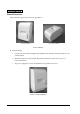
Confidential TM-U230 Developer’s Guide 259.5mm External Appearance 166mm 168mm 259.5mm 383.5mm Figure A-4 Without the power supply cover 166mm 168mm 258.
259.5mm 114.5mm Confidential 166mm 168mm 41mm 259.5mm Figure A-6 When placed on the desk with the power supply box 166mm 114.
Confidential TM-U230 Developer’s Guide 168mm 259.5mm 41 114.
Confidential Drawer Kick-out Connector The signal specified by the ESC p command is output to this connector. The host can check the status of input signal by the following commands. • DLE EOT • GS r • GS a (ASB) Drawer Kick-out Specifications Item Specifications Pin assignment See “Drawer kick-out connector pin assignment” table Model Drawer kick drive signal Printer side Molex 52018-6615 (or equivalent) User side 6-position 6-contact (RJ12 telephone jack) Output voltage Approx.
Confidential TM-U230 Developer’s Guide ❏ Two driver transistors cannot be driven simultaneously. ❏ Do not drive the drawer continuously. ❏ Be sure to use the printer power supply (conector pin 4) for the drawer power source. ❏ Do not connect a telephone line to the drawer kick-out connector. Pin Assignment Pin No.
Confidential Appendix A-10 Specifications
Appendix B: The table below shows the status when the parameter t2 of GS z 0 is 0 (default) or the internal buzzer is not configured by ESC(A command. When t2 = 0, DLE ENQ 0 can be used to return to the online status. (The PAPER OUT LED will be off.) When t2 ≠ 0, the printer recovers from the offline status automatically after a defined time is passed and the PAPER OUT LED will be off automatically.
Appendix C Comparison table Specifications Receive buffer TM-U230 TM-U210B TM-U300B Note, view point from application 16K / 1K 1K / 40 Byte 1K / 40 Byte buffer. Caution is required when handling the transmission data. To be busy when buffer capacity reachs 128 bytes remain <-- 16 Byte 512Byte/40Byte (300BM/U300BPM) <-- 10 Byte The BUSY tyming differs in TM-U230 and TM-U300B.
Appendix C Command comparison Command Function TM-U300B TM-U210B TM-U230 HT Horizontal tab Yes Yes (*1) Yes LF CR DLE EOT DLE ENQ ESC SP ESC ! Print and line feed Print and carriage Real-time status transaction Real-time request to printer Set right-side character spacing Select print mode Yes Yes No No Yes Yes Yes Yes Yes Yes Yes Yes Yes Yes Yes Yes Yes Yes ESC % Select /cancel user-defined character set Yes Yes(*1) Yes ESC & Define user-defined characters Yes Yes(*1) Yes ESC(A C
Appendix C Command comparison Command Function TM-U300B TM-U210B TM-U230 ESC R Select an international character set Yes(*5) Yes(*5) Yes(*6) ESC U ESC a ESC c 3 ESC c 4 ESC c 5 ESC d ESC e ESC i ESC m Turn unidirectional printing mode on / off Select justification Select paper sensor(s) to output paper-end signal Select paper sensor(s) to stop printing Enable / disable panel buttons Print and feed n lines Print and reserve feed n lines Execute partial-cut(one point left uncut) Execute partial-cut
Appendix C Opos function properties comparison Name Function Property to determine if concurrent printing on CapConcurrentJrnRec the journal and receipt stations is possible. Property to determine if concurrent printing on CapConcurrentJrnSlp the journal and slip station is possible. Property to determine if concurrent printing on CapConcurrentRecSlp the receipt and slip stations is possible. Property to determine if the printer’s cover is CapCoverSensor open.
Appendix C Opos function properties comparison Name CapRecLeft90 CapRecNearEndSensor CapRecPapercut CapRecPresent CapRecRight90 CapRecRotate180 CapRecStamp CapRecUnderline CapRecBitmap Function Property to determine if 90 degree left printing functions are present on the receipt station. Property to determine if there is a near end sensor on the receipt station. Property to determine if there is paper cutting functions available on the receipt station.
Appendix C Opos Direct-IO usage comparison Command DLE ENQ ESC & ESC < ESC ? ESC D ESC c 5 ESC ! Meaning Real time status requests Download character set load/cancel Download character definition Return home Download character destruction Set the horizontal tab positions Panel switch enable/disable Select print mode(s) ESC K Print and reverse feed paper.
Confidential
Confidential EPSON SEIKO EPSON CORPORATION Printed in Japan