
Specifications


Confidential
EPSON
TITLE
SHEET
REVISION
NO.
SHEET
NEXT
D
TM-U230
Specification
(STANDARD)
30 31
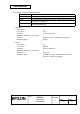
2.2.2 Power supply connector
This connector is used to connect the printer to an external power source.
1) Pin assignments: Refer to Table 2.2.1.
2) Model (printer side): Hosiden TCS7960-53-2010 (or equivalent)
Table 2.2.1 Power Supply Connector Pin Assignments
Pin Number Signal Name
1 + Power source
2 GND
3 NC
Shell FG
NOTE: Be sure to ground the frame ground (FG) screw on the board at the bottom of the unit.
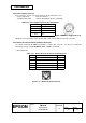
2.2.3 Drawer kick-out connector (modular connector)
The signal specified by the
ESC p
command is output to this connector. The host can confirm the
input signal state by using the
DLE EOT
,
GS a
, and
GS r
commands.
1) Pin assignments
Table 2.2.2 Drawer Kick-out Connector Pin Assignments
Pin No. Signal Name Direction
1 Frame GND --
2 Drawer kick-out drive signal 1 Output
3 Drawer open/close signal Input
4 +24 V --
5 Drawer kick-out drive signal 2 Output
6 Signal GND --
1
6
Figure 2.2.5 Drawer Kick-out Connector
Figure 2.2.4 Power Supply Connector