TM-U300C/U300D/U300PC/U300PD Operator’s Manual Using this online operator’s guide The words on the left side of this screen are bookmarks for all the topics in this guide. Use the scroll bar next to the bookmarks to find any topic you want. Click a bookmark to instantly jump to its topic. (If you wish, you can increase the size of the bookmark area by dragging the dividing bar to the right.) Use the scroll bar on the right side of this screen to move through the text.
1 station printer TM-U300C/U300D TM-U300PC/U300PD Operator’s Manual 400204504
All rights reserved. No part of this publication may be reproduced, stored in a retrieval system, or transmitted in any form or by any means, mechanical, photocopying, recording, or otherwise, without the prior written permission of Seiko Epson Corporation. No patent liability is assumed with respect to the use of the information contained herein. While every precaution has been taken in the preparation of this book, Seiko Epson Corporation assumes no responsibility for errors or omissions.
EMC and Safety Standards Applied Printer Product Name: TM-U300C/D, TM-U300PC/PD Model Name: M51JC/D, M51PC/PD AC Adapter Product Name:PA-6511/6513, PB-6509/6510 Model Name: M34PA, M34PB The following standards are applied only to the printers that are so labeled. (EMC is tested using the packaged AC adapter.) The following standards are applied only to the AC adapters that are so labeled. (The printer and the AC adapter together are applied to the EMC standards.
INTRODUCTION The TM-U300C-U300D and TM-U300PC/U300PD are compact, light-weight printers, designed to provide the highest possible performance to cost ratio.
CONTENTS Chapter 1 Unpacking the Printer ........................................................................... 1 1 1-3 Checking the Contents of the Printer Box ................................................... Choosing a Place for the Printer................................................................... Removingthe Transportation Damper.. ....................................................... 1-4 Part Names and Functions.....................................................................
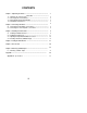
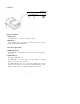
Chapter 1 Unpacking the Printer 1-1 Checking the Contents of the Printer Box The illustration below shows the items included for the standard specification printer. TM-U300C/U300PC l TM-U300D/U300PD AC adapter (*1) l n l Roll paper l 7 Ribbon cassette l Hexagonal lock screws (2 pcs) (*2) Operator’s Manual (*1) One of eight types of AC adapters may be included with your printer. Refer to Appendix A, Specifications for information on your AC adapter’s input voltage, dimensions, and weight.
1-2 Choosing a Place for the Printer n Avoid locations in direct sunlight or subject to excessive heat (such as near heaters). ■ Avoid using or storing the printer in places subject to excessive moisture. n Do not use or store the printer in a dusty or dirty area. n Choose a stable, horizontal surface for the printer. Avoid places subject to intense vibration or shock. W Make sure there is enough space around the printer so that it can be used easily.
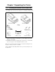
1-4 Part Names and Functions n Part names ➀ Take-up device cover (TM-U300C/U300PC) Roll paper cover (TM-U300D/U300PD) ➁ Printer cover ➄ Interface connector ➅ Drawer kick-out connector ➆ Power connector ➂ Control panel ➇ DIP switches ➃ Power switch TM-U300C/U300PC TM-U300D/U300PD 3
n Functions I 0 b Switches and Buttons ➀ POWER Switch The POWER switch is used to turn the printer on and off. ➁ FEED Button The FEED button is used to feed roll paper. The line feed amount is set by the printer commands ESC 2 and ESC 3. Control Panel Lights (LEDs) ➂ POWER LED (green) The POWER LED is on when the printer is turned on and off when the printer is turned off. ➃ PAPER LED (red) Normally the PAPER LED is off.
Chapter 2 Connecting the Cables 2-1 Connecting the AC Adapter to the Printer Follow these steps to connect the AC adapter to the printer: ➀ Make sure the printer is turned off. It is off when the O side of the switch is pressed down. ➁ Check the label on the AC adapter to make sure the voltage required by the AC adapter matches that of your electrical outlet.
2-2 Connecting the Host Computer to the Printer Connect the host ECR (host computer) to the printer using an interface cable that matches the specifications of the printer and the host ECR (host computer). Be sure to use a drawer that matches the printer’s specifications. ■ Connecting the host computer to the TM-U300C/U300D Connect the interface cable as follows: ➀ Turn off the printer and the host ECR (host computer).
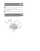
n Connecting the host computer to the TM-U300PC/U300PD Connect the interface cable as follows: ➀ Turn off the printer and the host ECR (host computer). ➁ Plug the parallel interface cable connector into the printer’s interface connector. ➂ Squeeze the wire clips together until they lock in place on both sides of the connector. ➃ Secure the frame ground cable and the shield wire of the parallel interface cable with the frame ground screw on the bottom of the printer.
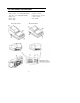
Chapter 3 Installing the Printer Parts 3-1 Installing the Ribbon Cassette ■ lnstalling the ribbon cassette Use Epson ribbon cassette ERC-34 (B/R). Follow these steps to install the ribbon cassette: ➀ Open the printer cover while lightly pressing the printer cover as shown below. ➁ Turn the ribbon-tightening knob in the direction of the arrow to take up any slack in the ribbon.
➂ Fit the ribbon between the print head unit and the ribbon mask. Then push the cassette firmly into position. Ribbon mask ➃ Turn the ribbon-tightening knob five or six times in the direction of the arrow to feed the ribbon smoothly into place between the print head unit and the ribbon mask. l Check that the ribbon is not twisted or creased. CAUTION: l Do not turn the ribbon-tightening knob in the reverse direction.
n Replacing the ribbon cassette Use Epson ribbon cassette ERC-34 (B/R). ➀ Open the printer cover while lightly pressing the printer cover as shown below. ➁ To remove the ribbon cassette, grasp the tab on the left side and lift the left side out first. ➂ To install a new ribbon cassette, follow steps ➁ through ➄ in the previous section, Installing the ribbon cassette.
3-2 Installing the Paper Roll n Installing the paper roll in the TM-U300C/U300PC Be sure to use roll paper that matches the printer’s specifications. See Appendix A, Specifications. ➀ Using scissors, cut the leading edge of the roll paper so that it is perpendicular to the paper feed direction. Correct Incorrect Incorrect ➁ Open the take-up device cover and remove the take-up spool from the printer. ➂ Load the paper roll while lightly pressing the left paper roll holder outward.
➃ Turn on the printer. The POWER LED goes on. ➄ While leaving some slack in the paper roll, insert the end of the roll paper straight into the paper inlet. The printer automatically feeds the roll paper into the printer (semi-automatic loading). ➅ Press the FEED button to continue feeding the paper until it extends about 20 cm (8 inches) beyond tear-off edge.
➇ Install the take-up spool in the printer. Make sure that the gear on the take-up spool aligns with the gear on the printer. ➈ Close the take-up device cover. ➉ Tear off any extra paper at the tear-off edge by pulling the paper toward you. CAUTION: • The extra paper must be torn off after closing the take-up device cover so that roll paper comes out correctly from the paper exit.
n Installing the paper roll in the TM-U300D/U300PD Be sure to use roll paper that matches the printer’s specifications. See Appendix A, Specifications. ➀ Using scissors, cut the leading edge of the roll paper so that it is perpendicular to the paper feed direction. L Incorrect ➁ Open the roll paper cover.
➂ Load the roll paper while lightly pressing the paper roll holder outward. Release the holder after fitting the paper core onto the holder. Make sure the paper roll turns freely and be sure to load the paper roll so it rotates in the correct direction. Correct Incorrect ➃ Turn on the printer. The POWER LED goes on. ➄ While leaving some slack in the paper roll, Insert the end of the roll paper straight into the paper inlet.
➅ Close the roll paper cover. ➆ Tear off any extra paper at the tear-off edge by pulling the paper toward you. CAUTION: The extra paper must be torn off after closing the roll paper cover so that roll paper comes out correctly from the paper exit.
■ Replacing the roll paper for TM-U300C/U300PC Be sure to use roll paper that matches the printer’s specifications. See Appendix A, Specifications. ➀ Open the take-up device cover. ➁ Remove the take-up spool from the printer. (If it is necessary, cut the paper going to the take-up spool, using the tear-off edge.) Then remove the roll paper core. If there is roll paper remaining, cut the paper straight across using scissors at the place shown in illustration below.
■ Replacing the paper roll in the TM-U300D/U300PD Be sure to use roll paper that matches the printer's specifications. See Appendix A, Specifications. ➀ Open the roll paper cover. ➁ Remove the roll paper core. If there is roll paper remaining, cut the paper straight across using scissors at the place shown in illustration below. ➂ While pressing the FEED button, remove the remaining roll paper in the printer by pulling the paper lightly out in the direction of the arrow.
3-3 Adjusting the Paper Near-End Detector Location ■ The paper near-end detector When the paper near-end detector senses that the paper is almost out, the printer turns on the PAPER LED. The PAPER LED also turns on when the paper is completely out or paper roll is not installed. ■ Adjusting the paper near-end detector Because the paper roll core size differs depending on the paper roll, you may need to adjust the paper near-end detector location. ➀ Make sure the paper core inside diameter is 10.5 to 12.
➃ Referring to the illustration below, set the position detector plate to the appropriate position according to the adjustment position number from the table above. TM-U300C/U300PC TM-U300D/U300PD NOTES: 1. Since the adjustment values in the Table 3-1 are calculated value, there may be some variations depending on the printer. 2. If roll paper with a red end mark at the paper end is used, this mark may cause the paper to stick together. If this occurs, the paper near-end detector may operate incorrectly.
3-4 Inserting a Cut Sheet (Validation Paper) Be sure to use a validation paper that matches the printer’s specifications. Refer to Appendix A, Specifications. ➀ Check that the paper is not wrinkled. Using creased or wrinkled paper may cause a paper jam. ➁ Check that the paper roll is already installed. If not, install it first. CAUTION: Printing with no roll paper installed in the printer may cause damage to the print head pin.
n Notes on printing on validation paper l l l l l l The printer can print only one line on validation paper. Printing is performed by the print commands, but the paper is not fed. Therefore, double-height printing cannot be performed on validation paper. Printing on the validation paper must be performed when roll paper is loaded. However, printing is affected by the total thickness of the paper.
Chapter 4 Setting the DIP Switches n Finding the DIP switches As shown in the illustration below, the DIP switches are located on the bottom of the printer. The DIP switches are used to set the printer to perform various functions l The TM-U300C/U300D DIP switches are numbered SW-1 to SW-10 and the TM-U300PC/U300PD DIP switches are numbered SW-1 to SW-8, from left to right as shown in figure below. l The tables on the following pages describes the DIP switch functions.
n TM-U300C/U300D DIP Switch Functions Table 4-1. TM-U300C/U300D DIP Switch Functions Refer to Table 4-2. Baud rate selection ( ) Do not change the settings of DIP switches 9 and 10 on the TM-U300C/U300D * Table 4-2.
n TM-U300PC/U300PD DIP Switch Functions Table 4-3. TM-U300PC/U300PD DIP Switch Functions (* ) Do not change the settings of DIP switches 3 through 6 on the TM-U300PC/U300PD.
Chapter 5 The Self Test ■ The purpose of the self test The self test checks whether the printer has any problems. If the printer does not function properly, contact your dealer. The self test checks the following: l Control ROM version l Control circuit functions l DIP switch settings l Printer mechanism l Print quality l Presence or absence of a validation detector n Running the self test ➀ Make sure the ribbon cassette and paper roll have been installed properly.
Chapter 6 Removing Jammed Paper 6-1 Removing Jammed Paper Turn the paper-feed knob as shown below, and remove any jammed paper. It may be easier if you cut the roll paper or remove the printer cover. CAUTION: Be careful not to touch the tear-off edge.
Appendix Appendix A. Specifications 1. Printing Specifications Printing method: Serial impact dot matrix Head wire arrangement: Serial-type, 9-pin Printing directions: Bi-directional (logic seeking) Lines per second: Approx. 3.5 LPS (40 columns, 16 CPI, single color, continuous printing) Approx. 5.8 LPS (20 columns, 16 CPI, single color, continuous printing) NOTES: l l When printing exceeds the allowable duty cycle, the actual printing speed may be slower than that listed above.
Table A-1. Character Size, Characters Per Inch, Characters Per Line ( 1) The 7 x 9 font is the default. * Example 7 x 9 font Units: mm (inch) 3. Ribbon Ribbon cassette type: Exclusive ribbon cassette ERC-38 Color: Black and Red, Black, Red Single-color ribbons [Part No.: ERC-34 (P) (purple) or ERC-34 (B) (black)] and P-color ribbon [Part No.: ERC-34(B/R) (black and red)] are also available. When using these ribbons, the print color selection command (ESC r) must not be used.
Ribbon cassette overall dimensions: Refer to Figure A-1 [Units: mm] Figure A-1. ERC-38 Overall Dimensions 4. Roll Paper Supply Device Supply method: Paper roll holding shaft Near-end detector: Provided inside the printer case The paper near-end detector location should be adjusted by the user. Refer to section 3-3, Adjusting the Paper Near-End Detector Location. l l Roll paper core inside diameter: ø 10.5 to 12.5 mm (0.41" to 0.49") Near-end adjustment: Adjustable slider 5.
Paper size: l Roll paper Paper width: 76 mm ± 0.5 mm (2.99" ± 0.02") Maximum diameter: ø 83 mm (3.27") (when 2-ply or 3-ply paper is used) ø 60 mm (2.36") (when 1 -ply paper is used) Paper core inside diameter: ø 10.5 to 12.5 mm (0.41" to 0.49") ➀ Normal paper Paper thickness: (single-ply sheet) 0.06 to 0.085 mm (0.002" to 0.003’) Weight: 52.
10. Environmental Conditions Temperature: Operating: 5° to 40°C (41° to 104°F) Storage: For the TM-U300C/U300PC, when the temperature is 30°C (86°F) or more, the operating humidity is limited.