TM-U300A/U300B/U300PA/U300PB Operator’s Manual Using this online operator’s guide The words on the left side of this screen are bookmarks for all the topics in this guide. Use the scroll bar next to the bookmarks to find any topic you want. Click a bookmark to instantly jump to its topic. (If you wish, you can increase the size of the bookmark area by dragging the dividing bar to the right.) Use the scroll bar on the right side of this screen to move through the text.
1 station printer TM-U300A/U300B TM-U300PA/U300PB Operator’s Manual 400137504
All rights reserved. No part of this publication may be reproduced, stored in a retrieval system, or transmitted in any form or by any means, mechanical, photocopying, recording, or otherwise, without the prior written permission of Seiko Epson Corporation. No patent liability is assumed with respect to the use of the information contained herein. While every precaution has been taken in the preparation of this book, Seiko Epson Corporation assumes no responsibility for errors or omissions.
EMC and Safety Standards Applied Printer Product Name: TM-U300A/B, TM-U300PA/PB Model Name: M51JA/B, M51PA/PB AC Adapter Product Name:PA-6511/6513, PB-6509/6510 Model Name: M34PA, M34PB The following standards are applied only to the printers that are so labeled. (EMC is tested using the packaged AC adapter.) The following standards are applied only to the AC adapters that are so labeled. (The printer and the AC adapter together are applied to the EMC standards.
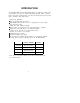
INTRODUCTION The TM-U300A/U300B and TM-U300PA/U300PB printers are designed to provide a high cost-performance ratio. They are compact, light-weight, and highly reliable one-station printers using plastic mechanical frames. They have the following features and are applicable to the POS 1 station printer market. Compact and light-weight. l * High speed printing using logic-seeking. . High reliability and long life due to the use of stepping motors for both carriage return and paper feeding.
CONTENTS Chapter 1 Unpacking the Printer ........................................................................... 1-1 Checking the Contents of the Box .................................................................. 1-2 Choosing a Place for the Printer.. ................................................................... 1-3 Removing the Transportation Damper.. ......................................................... 1-4 Names and Functions of Parts ....................................................
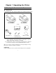
Chapter 1 Unpacking the Printer 1-1 Checking the Contents of the Box n Checking the parts The illustration below shows the items included for the standard specification printer. TM-U300A/U300PA TM-U300B/U300PB l l l AC adapter (*1) l Printer Ribbon cassette Hexagonal lock screws (2 pcs) (*2) l l Roll paper Operator’s Manual (*1) One of eight types of AC adapters may be included with your printer.
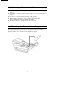
1-2 n n n n n Choosing a Place for the Printer Avoid locations that are subject to direct sunlight or excessive heat (near heaters). Avoid using or storing the printer in places subject to excessive temperatures or moisture. Do not use or store the printer in a dusty or dirty location. When setting up the printer, choose a stable, horizontal location. Intense vibration or shock may damage the printer. Ensure the printer has enough space to be used easily.
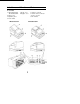
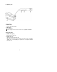
1-4 Names and Functions of Parts n Part names ➀ TM-U300A/U300PA: TM-U300B/U300PB: ➁ Printer cover ➂ Operation panel ➃ Power switch TM-U300A/U300PA Take-up cover Roll-paper cover ➄ Interface connector ➅ Drawer kick-out connector ➆ Power connector ➇ DIP switches TM-U300B/U300PB
n Operation panel Panel Switches ➀ POWER switch Turn the printer ON and OFF. ➁ FEED switch Feeds roll paper. * Feeds roll paper based on the line feed amount set by ESC 2 and ESC 3. Panel Lights (LED) ➂ POWER LED (green) On when power is turned on. ➃ PAPER LED (red) On when the paper roll near the end. Blinks when an error has been detected, when the printer is in the test printing standby state, or when printing has stopped due to exceeding the allowable print duty cycle.
Chapter 2 Before Setting Up 2-1 Connecting the AC Adapter to the Printer n Plugging in AC adapter CAUTIONS: * Before connecting the printer to the power supply, make sure that the voltage and power specifications match the printer’s requirements. - Using an incorrect power supply can cause serious damage to the printer. Connect the AC adapter according to the following procedure. ➀ Make sure the printer is turned off.
2-2 Connecting the Host Computer to the Printer n Connecting the interface cable Connect the printer with the host ECR (host computer) through an interface cable matching the specifications of the printer and the host ECR (host computer). Be sure to use a drawer that matches the printer’s specifications. Connect the interface cable according to the following procedure. ➀ Turn off the printer and the ECR (host computer).
Connect the interface cable according to the following procedure. ➀ Turn off the printer, and the ECR (host computer). ➁ Plug the interface cable connector into the interface connector on the printer. ➂ Squeeze the wire clips together until they lock in place on both sides of the connector. ➃ Attach the ground wire to the ground connector on the bottom of the printer. ➄ Plug the drawer kick-out cable connector into the drawer kick-out connector on the printer.
Chapter 3 Installing the Parts 3-1 Installing the Ribbon Cassette n Installing the ribbon cassette Be sure to use a ribbon cassette that matches the printer’s specifications. ➀ Open the printer cover. ➁ Turn the ribbon-tightening knob in the direction of the arrow to take up any slack in the ribbon.
➂ Fit the ribbon between the head unit and the ribbon mask. Then push the cassette firmly into position. ➃ Turn the ribbon-tightening knob five or six times in the direction of the arrow to feed the ribbon smoothly into place between the head unit and the ribbon mask. - Check that the ribbon is not twisted or creased. CAUTION: . Do not turn the ribbon-tightening knob in the reverse direction. ➄ Close the printer cover.
■ Exchanging the ribbon cassette Be sure to use a ribbon cassette that matches the specifications. ➀ Open the printer cover. ➁ When removing the ribbon cassette, grasp the tab on the left side and lift the left side out first. ➂ Install a new ribbon cassette. See 3-1 Installing the Ribbon Cassette ➁ to ➄.
3-2 Installing the Roll Paper n Installing the roll paper for TM-U300A/U300PA Be sure to use roll paper that matches the printer’s specifications. ➀ Using scissors, cut the leading edge of the roll paper perpendicular to the paper feed direction. l-H.-Au. Good Bad Bad ➁ Open the printer cover and the take-up cover. l Check that the ribbon cassette is properly installed. ➂ Load the roll paper while lightly pressing the left roll-paper holder outward.
➃ Turn on the printer. ➄ While leaving some slack in the roll paper, insert the end of the roll paper straight into the paper inlet. The printer automatically feeds the roll paper into the printer. ➅ Press the FEED switch to continue feeding the paper until it extends about 20 cm beyond tear-off edge. ➆ Remove the take-up spool from the take-up frame.
➇ Install the take-up spool to the take-up frame. ➈ Tear off the receipt paper by the cutter when using the 2-ply paper and 3-ply paper. ➉ Close the printer cover and the take-up cover.
■ Installing the roll paper for TM-U300B/U300PB Be sure to use roll paper that matches the printer's specifications. ➀ Using scissors, cut the leading edge of the roll paper perpendicular to the paper feed direction. Good Bad Bad ➁ Open the printer cover and the roll-paper cover. l Check that the ribbon cassette is properly installed. ➂ Load the roll paper while lightly pressing the left roll-paper holder outward. Release the holder after fitting the paper core onto the holder.
➃ Turn on the printer. ➄ While leaving some slack in the roll paper, insert the end of the roll paper straight into the paper inlet. The printer automatically feeds the roll paper into the printer. Roll Paper ➅ Tear off any extra paper at the tear-off edge by pulling the paper toward you. ➆ Close the printer cover and the roll-paper cover.
n Exchanging the paper roll Be sure to use roll paper that matches the printer’s specifications. ➀ Open the printer cover and the take-up cover. Remove the journal paper and the receipt paper. While pressing the FEED switch, remove the remaining paper by pulling it out in the direction of the arrow. ➁ Install a new roll paper. See Installing the Roll Paper for TM-U300A/U300PA ➀ to ➉. ➀ Open the printer cover and the roll-paper cover. Remove the roll paper.
3-3 Adjusting the Paper Near-End Detector ■ The paper near-end detector The paper near-end detector senses when the paper is nearing its end and turns on the PAPER LED. The paper near-end detector can be adjusted according the thickness of the paper core. n Adjusting the paper near-end detector Roll paper differs in paper core size, so you may need to adjust the paper nearend detector. ➀ Make sure the paper core inside diameter (Ød) is 10.5 to 12.5 mm.
➃ The adjusting screw which holds the roll paper near-end detector, may be loosened and then set the top of “B” to the adjustment value found in ➂, and tighten the adjusting screw. (The adjusting screw can be turned with a coin.) Screw ➄ Be sure that the detecting lever operates smoothly after finishing the adjustment. NOTES: l Since the adjustment values in Table 3-1 are calculated from standard measurements, there may be some variations depending on the model.
3-4 DIP Switches n Locating DIP switches On the bottom of your printer are DIP switches that allow the printer to be set or perform a number of different functions. . The switches are numbered SW-1 to SW-10 (TM-U300A/U300B) or SW-1 to SW-8 (TM-U300PA/U300PB), from left to right as shown in figure below. . The lists on the following page describe each switch’s function. ■ Setting the DIP switches Follow these steps when changing DIP switch settings. ➀ Turn the printer power switch off.
n TM-U300A/U300B DIP Switch Functions Table 3-2. TM-U300A/U300B DIP Switch Functions Switch Function ON OFF SW-1 Data receive error Ignored Prints “?” SW-2 Receive buffer capacity 40 bytes Approx. 1 Kbyte SW-3 / Handshaking SW-4 Word length 7 bits 8 bits SW-5 Parity check On Off SW-6 Parity selection Even Odd SW-7 ( XON/XOFF ( DSR/DTR Baud rate selection (Refer to Table 3-3.
Chapter 4 The Self Test 4-1 The Self Test n The purpose of the self test The self test checks whether the printer has any problems. When the printer does not function properly, contact the dealer. The self test checks the following - Control circuit functions - Printer mechanism functions * Print quality n Running the self test Run the self test only when roll paper is loaded the printer. ➀ Make sure the ribbon cassette and paper have been installed properly.
Chapter 5 Removing Jammed Paper 5-1 Removing Jammed Paper ■ Removing jammed paper Remove jammed paper according to the following steps. ➀ Open the roll-paper take-up cover (TM-U300A/U300PA) or the roll-paper cover (TM-U300B/U300PB). ➁ Then turn the paper-feed knob and remove any jammed paper. ➂ Reload roll paper, and close the roll-paper take-up cover (TM-U300A/U300PA) or the roll-paper cover (TM-U300B/U300PB). See 3-2, Installing the Roll Paper.
APPENDIX APPENDIX A General Specifications 1. Printing specifications Printing method: Serial impact dot matrix Head wire arrangement: Serial-type 9 pin Printing directions: Bi-directional (logic-seeking) Lines per second: Approx. 3.5 LPS (40 columns, 16 CPI, Single color continuous printing) Approx. 5.6 LPS (20 columns, 16 CPI, Single color continuous printing) In the case of heavy use, printing stops to * protect the head. In this case the actual lines per second may be lower.
Table A-1. Character Size, Characters Per Line, Characters Per Inch ( 1) 7 X 9 font is the default. ( 2) ANK: Alphanumeric and Kana * * [Units: mm] Example) 7 X 9 font 1.59 1.24 3. Ribbon Ribbon cassette type: Exclusive ribbon cassette ERC-38 ( *) Color: Black and Red, Black, Purple Ribbon life: Black: Approx. 1,500,000 characters (In case of using 2-color type) Red: Approx. 750,000 characters Ribbon cassette overall dimensions: Refer to Figure A-1 Units: mm1 Figure A-1.
[Condition] * Character font: 7 X 9 font (with descenders) * Printing pattern: ASCII 96-character rolling pattern continuous printing - Temperature: 25°C 4. Roll paper supply device Roll paper shaft-support loading Supply method: Near-end detector: Micro switch - Detection method: - Roll paper core inside diameter: Ø 10.5 to 12.5 mm Adjustable slider (Refer to 3-3, Adjusting the Paper Near-End Detector) - Near-end adjustment: 5.
Maximum diameter: Ø 83 mm (When 2-ply or 3-ply paper is used. When 1-ply paper is employed, the maximum diameter shall be Ø 60 mm.) Paper core inside diameter: Ø 10.5 to 12.5 mm * Normal paper Paper thickness: 0.06 to 0.85 mm Weight: 52.3 g/m2 to 64 g/m2 (45 to 55 kg/1000 sheets/1091 X 788 mm) * Pressure sensitive paper Maximum 1 original + 2 copies. Copy capability is considerably affected by the ambient temperature. Refer to table A-2. Relationship between Ambient Temperature and Number of Copies.
Humidity: Storage: -10 to 50°C (excluding paper and ribbon cassette) Operating: 20 to 80°C (non-condensing) Storage: 20 to 90% (non-condensing, excluding paper and ribbon cassette) Figure A-2.