U925_eng.
U925_eng.
U925_eng.book Page i Thursday, July 25, 2002 9:15 AM All rights reserved. No part of this publication may be reproduced, stored in a retrieval system, or transmitted in any form or by any means, mechanical, photocopying, recording, or otherwise, without the prior written permission of Seiko Epson Corporation. No patent liability is assumed with respect to the use of the information contained herein.
U925_eng.book Page ii Thursday, July 25, 2002 9:15 AM EMC and Safety Standards Applied Product Name: TM-U925 Model Name: M62UA The following standards are applied only to the printers that are so labeled. (EMC is tested using the EPSON power supply.) Europe: CE Marking Safety: EN60950 North America: EMI: FCC/ICES-003 Class A Safety: UL 1950/CSA C22.2 No.
U925_eng.book Page iii Thursday, July 25, 2002 9:15 AM CE Marking The printer conforms to the following Directives and Norms Directive 89/336/EEC EN 55022 Class B EN 55024 IEC 61000-4-2 IEC 61000-4-3 IEC 61000-4-4 IEC 61000-4-5 IEC 61000-4-6 IEC 61000-4-8 IEC 61000-4-11 Directive 90/384/EEC EN45501 FCC Compliance Statement For American Users This equipment has been tested and found to comply with the limits for a Class A digital device, pursuant to Part 15 of the FCC Rules.
U925_eng.book Page iv Thursday, July 25, 2002 9:15 AM GEREÄUSCHPEGEL Gemäß der Dritten Verordnung zum Gerätesicherheitsgesetz (Maschinenlärminformations- Verordnung-3. GSGV) ist der arbeitsplatzbezogene Geräusch-Emissionswert kleiner als 70 dB(A) (basierend auf ISO 7779).
U925_eng.book Page v Thursday, July 25, 2002 9:15 AM Introduction Features The TM-U925 is a high-quality POS printer that can print on both slip and roll paper. The printer has the following features: ❏ Wide slip paper capability (maximum characters per line: 88 with 7 x 9 font). ❏ Interface connector within the printer’s external dimensions. ❏ High throughput using bidirectional, minimum distance printing. ❏ Precision paper feeding at 0.176mm {1/144 inch}.
U925_eng.book Page vi Thursday, July 25, 2002 9:15 AM About This Manual Setting Up and Using ❏ Chapter 1 contains information on unpacking the printer, setting it up, running the self test, setting the DIP switches, and adjusting the paper near end detector. ❏ Chapter 2 contains information on using the printer, including the optional MICR reader. ❏ Chapter 3 contains troubleshooting information, including how to clean the optional MICR reader. Reference ❏ Chapter 4 contains specifications.
U925_eng.book Page 1 Thursday, July 25, 2002 9:15 AM Contents Chapter 1 Setting Up the Printer Opening and Closing the Printer Cover . . . . . . . . . . . . . . . . . . . . . . . . . . . . . . . . . . . 1-1 Unpacking . . . . . . . . . . . . . . . . . . . . . . . . . . . . . . . . . . . . . . . . . . . . . . . . . . . . . . . . . . . . 1-2 Removing the protective material . . . . . . . . . . . . . . . . . . . . . . . . . . . . . . . . . . . . 1-2 Connecting the Printer to Your Computer . . . . . . . . .
U925_eng.book Page 2 Thursday, July 25, 2002 9:15 AM Chapter 4 Reference Information Printing Specifications . . . . . . . . . . . . . . . . . . . . . . . . . . . . . . . . . . . . . . . . . . . . . . . . . 4-1 Character Specifications . . . . . . . . . . . . . . . . . . . . . . . . . . . . . . . . . . . . . . . . . . . . . . . 4-2 Ribbon Specifications . . . . . . . . . . . . . . . . . . . . . . . . . . . . . . . . . . . . . . . . . . . . . . . . . . 4-3 MICR Specifications (Option) . . . . . . . . . .
U925_eng.book Page 1 Thursday, July 25, 2002 9:15 AM Chapter 1 Setting Up the Printer Opening and Closing the Printer Cover Use these instructions whenever you need to open or close the printer. Open the printer by pushing the cover-open button and then lifting the printer cover. Close the printer by pressing on the indentation on the right side of the printer cover until it audibly clicks into place.
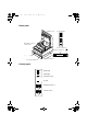
U925_eng.book Page 2 Thursday, July 25, 2002 9:15 AM Unpacking The illustration below shows the items included for the standard specification printer. Ribbon Paper roll Printer Hexagonal lock screws Caution label Power switch cover See the note on page 1-3 for information about the hexagonal lock screws. See the power switch cover section in Chapter 2 for information about the cover. See the slip paper handling section in Chapter 2 for information about the label.
U925_eng.book Page 3 Thursday, July 25, 2002 9:15 AM Store the protective material with the other packing materials and use it when transporting your printer. Connecting the Printer to Your Computer Follow the procedures below only when you use the printer as a single unit (not connected to an intelligent module). When you use the printer with the intelligent module, see the IM-403/405 User's Guide for details.
U925_eng.book Page 4 Thursday, July 25, 2002 9:15 AM 3. Attach the other end of the cable into the computer. 4. Plug the power supply's power cord into an electrical outlet. Connecting the Printer to the Drawer Connector Follow the procedures below to connect a drawer to the printer only when you use the printer as a single unit (not connected to an intelligent module). When you use the printer with the intelligent module, see the IM-403/405 User's Guide for details.
U925_eng.book Page 5 Thursday, July 25, 2002 9:15 AM Note: To remove the cable connector, squeeze the connector's clip and pull it out. Connecting to a Direct Connection Display Module If you are using the printer as a single unit (not connected to an intelligent module) and you plan to connect a direct connection display module, follow the steps below. When you use the printer with the intelligent module, see the IM-403/405 User's Guide for details. 1. Make sure that the printer is turned off. 2.
U925_eng.book Page 6 Thursday, July 25, 2002 9:15 AM Note: To remove the cable, squeeze the connector and pull it out. Connecting the Power Supply When the printer is used as a single unit, not connected to an intelligent module, use the optional EPSON PS-170 power supply for your printer. When the printer is connected to an intelligent module, the power is supplied by the intelligent module. See the IM-403/405 User's Guide for details. CAUTION: Make sure that you use the EPSON PS-170 power supply.
U925_eng.book Page 7 Thursday, July 25, 2002 9:15 AM 3. Plug in the power supply's cable as shown below. Notice that the flat side of the plug faces down. Note: To remove the DC cable connector, make sure that the power supply's power cord is unplugged; then grasp the connector at the arrow and pull it straight out. Grounding the Printer When you use the printer as a single unit (not connected to an intelligent module), you need an appropriate ground wire to ground your printer. 1.
U925_eng.book Page 8 Thursday, July 25, 2002 9:15 AM Installing the Ribbon Cassette Use Epson ERC-31 (P) ribbon cassette for your printer. CAUTION: Never turn the ribbon cassette's feed knob in the opposite direction of the arrow marked on the cassette. 1. Turn on the printer and open the printer cover. 2. Turn the ribbon cassette's knob two or three times in the direction of the arrow to take up any slack in the ribbon. Tab 3.
U925_eng.book Page 9 Thursday, July 25, 2002 9:15 AM Make sure that the ribbon is installed in front of the print head without wrinkles or creases. If it is hard to see, open the print head cover as described in Chapter 3. If the ribbon is not installed correctly, remove the cassette as described below and repeat steps 2 and 3 above. Note: To remove the ribbon cassette, grasp the ribbon cassette's tab and pull it out of the printer. See the illustration in step 2 above for the location of the tab.
U925_eng.book Page 10 Thursday, July 25, 2002 9:15 AM 3. Insert a paper roll, as shown below. Correct Wrong 4. Insert the tip of the paper into the paper inlet and push it in until it is automatically detected and fed into the printer. 5. Tear off the paper on the cutter. If the paper was not fed far enough, press the RECEIPT FEED button to feed additional paper.
U925_eng.book Page 11 Thursday, July 25, 2002 9:15 AM Note: To remove the paper roll, hold down the paper release lever (marked PRESS) and pull out the paper roll in the direction shown in the illustration. Paper release lever Self Test The self test lets you know if your printer is operating properly. You can run the self test with either roll paper or slip paper. Running the self test with roll paper 1. Make sure the printer is turned off and the printer cover is closed properly. 2.
U925_eng.book Page 12 Thursday, July 25, 2002 9:15 AM The printer is ready to receive data as soon as it completes the self test. Note: If you want to pause the self test manually, press the RECEIPT FEED button. Then press the RECEIPT FEED button to continue the self test. Running the self test with slip paper Note: Be sure to install the paper roll to prevent slip paper jams. 1. Make sure the printer is turned off and the printer cover is closed properly. 2.
U925_eng.book Page 13 Thursday, July 25, 2002 9:15 AM Setting the DIP Switches DIP switch functions Your printer has two sets of DIP switches. The functions of the switches are shown in the tables below.
U925_eng.
U925_eng.book Page 15 Thursday, July 25, 2002 9:15 AM CAUTION: Turn off the printer while removing the DIP switch cover to prevent an electric short, which can damage the printer. 1. Make sure the printer is turned off. 2. Remove the screw from the DIP switch cover. Then take off the DIP switch cover, as shown in the illustration below. DSW DSW1 DSW2 DSW2 3. Set the switches using a pointed tool, such as tweezers or a small screwdriver.
U925_eng.book Page 16 Thursday, July 25, 2002 9:15 AM 4. Replace the DIP switch cover by inserting it upward and sliding it to the left as shown below. Then secure it with the screw. DSW DSW2 1 2 5. The new settings take effect when you turn on the printer. Adjusting the Paper Near End Detector The paper near end detector detects when the paper is almost gone by measuring the diameter of the paper roll. Software programs can use the ESC c 4 command to stop printing when the paper is almost gone.
U925_eng.book Page 17 Thursday, July 25, 2002 9:15 AM 2. Determine the point on the paper roll at which you want the paper roll end detection to be triggered. Then measure the distance A shown in the illustration. distance A Note: There may be some difference between the measured distance A and the actual sensing position. 3. Find the corresponding adjustment position number from the table below. Distance A Adjustment position number 10 mm (0.39 inch) #1 8 mm (0.32 inch) #2 6 mm (0.
U925_eng.book Page 18 Thursday, July 25, 2002 9:15 AM 4. Locate the adjusting screw and the positioning plate shown in the illustration below. #5 #4 #3 #2 #1 Loosen Secure 5. Loosen the adjusting screw with a coin or a screwdriver.Move the positioning plate to the appropriate position and then tighten the adjusting screw, as shown below. Position 1 leaves the least paper on the roll, and position 5 leaves the most 6. Be sure that the detecting lever moves freely after you finish the adjustment. 7.
U925_eng.book Page 1 Thursday, July 25, 2002 9:15 AM Chapter 2 Using the Printer Operating the Control Panel You can control the basic paper feeding operations of the printer with the buttons on the control panel. The indicator lights help you monitor the printer’s status.
U925_eng.book Page 2 Thursday, July 25, 2002 9:15 AM SLIP FEED You cannot load slip paper using this button. Slip paper can be loaded only by selecting slip paper with a command and then inserting the paper. When the printer is in the slip paper mode (the SLIP light is on or blinking) and slip paper is inserted, you can press the SLIP FEED button once to advance slip paper one line or hold down SLIP FEED to feed slip paper continuously.
U925_eng.book Page 3 Thursday, July 25, 2002 9:15 AM RECEIPT OUT (red) The RECEIPT OUT light is on (not blinking) when the paper roll is not installed or is at or near the end. The RECEIPT OUT light blinks after the self test prints the printer settings on the roll paper. SLIP (green) The SLIP light is on or blinking while the printer is in slip paper mode. The SLIP light blinks while the printer is waiting for slip paper to be inserted or removed.
U925_eng.book Page 4 Thursday, July 25, 2002 9:15 AM Note: Place the caution label, which reminds you how to insert slip paper, on the printer as shown in the illustration below, if necessary. CAUTION: Be sure to put the caution label exactly in the position shown. If you put it another place, such as over the slip paper inlet, the printer may be damaged.
U925_eng.book Page 5 Thursday, July 25, 2002 9:15 AM Using the Power Switch Cover You can use the enclosed power switch cover to make sure that the power switch is not accidentally pressed. If you want to use this cover, install it as shown in the illustration below. Using the MICR Reader (Option) If your printer has the factory installed optional Magnetic Ink Character Recognition (MICR) reader that enables the printer to read and process MICR characters on personal checks, read this section.
U925_eng.book Page 6 Thursday, July 25, 2002 9:15 AM CAUTION: Do not insert checks with staples in them. This may cause paper jams, MICR reading errors, and damage to the MICR head. Be sure that the checks are flat, without curls, folds, or wrinkles. 1. Wait until the computer sends the FS a 0 command to the printer, causing it to enter the MICR mode. The SLIP light blinks. 2. Turn the check over so that it is face down with the MICR characters on the righthand side, as shown in the illustration below.
U925_eng.book Page 7 Thursday, July 25, 2002 9:15 AM 4. Insert the check as far as it will go. The printer will detect the check and start drawing it in. 5. When the printer starts drawing it in, let go of the check immediately. The SLIP light quits blinking but stays on. 6. When printing and MICR reading are finished, the printer ejects the check and the SLIP light starts blinking again. 7. Remove the check by pulling it straight up; do not pull it at an angle. The SLIP light goes off.
U925_eng.
U925_eng.book Page 1 Thursday, July 25, 2002 9:15 AM Chapter 3 Troubleshooting Troubleshooting This chapter gives solutions to some of the more common printer problems. General problems The lights on the control panel do not come on. Make sure that the power supply cables are correctly plugged into the printer, the power unit, and to the power outlet. Make sure that power is supplied to the power outlet. If the outlet is controlled by a switch or timer, use another outlet.
U925_eng.book Page 2 Thursday, July 25, 2002 9:15 AM The ERROR light is blinking and the printer does not print. First, turn off the printer and check for a paper jam. (See the paper jam description on page 3-3.) If there is no paper jam and the printer has been printing for quite a while, the print head may be overheated. If the print head is overheated, the printer will resume printing when the head has cooled (usually within two or three minutes).
U925_eng.book Page 3 Thursday, July 25, 2002 9:15 AM The printer sounds like it is printing, but nothing is printed. The ribbon cassette may not be installed properly. See the instructions in Chapter 1. The ribbon may be worn out. Replace the ribbon cassette as described in Chapter 1. The printout is faint. The ribbon may be worn out. Replace the ribbon cassette as described in Chapter 1. A line of dots is missing in the printout. The print head may be damaged.
U925_eng.book Page 4 Thursday, July 25, 2002 9:15 AM 2. Cut the paper as shown in the illustration, using a pair of scissors or a knife; then remove the paper roll. cut 3. If the paper is caught in the automatic cutter blade, open the cutter blade by rotating the gear in the direction shown in the illustration.
U925_eng.book Page 5 Thursday, July 25, 2002 9:15 AM 4. Move the OPEN <-> LOCK lever on each side of the printer in the direction shown in the illustration; the cutter unit then opens automatically. OPEN LOCK 5. Pull the paper out gently. If the paper tears, make sure you remove any remaining pieces. 6. If you encounter difficulty in clearing a paper jam, remove the print head cover by loosening the screw on the right side of the cover, as shown in the illustration below.
U925_eng.book Page 6 Thursday, July 25, 2002 9:15 AM CAUTION: Do not touch the print head because it can be very hot after printing continuously for a long time. 7. Remove any paper from inside the printer. 8. If you removed the print head cover, replace the cover and secure the screw, as shown in the illustration below. 9. Close the cutter unit and lock it by moving both OPEN <-> LOCK levers in the direction shown in the illustration.
U925_eng.book Page 7 Thursday, July 25, 2002 9:15 AM CAUTION: Make sure you lock the cutter unit with both OPEN <-> LOCK levers. OPEN LOCK 10. Install the paper roll following the steps in Chapter 1; then close the printer cover. Cleaning the MICR Mechanism Foreign matter on any part of the MICR mechanism can cause MICR reading errors. Cleaning the MICR mechanism is simple. First, send the cleaning command (FS c) to the printer.
U925_eng.book Page 8 Thursday, July 25, 2002 9:15 AM Hexadecimal Dump This feature allows experienced users to see exactly what data is coming to the printer. This can be useful in finding software problems. When you turn on the hex dump function, the printer prints all commands and other data in hexadecimal format along with a guide section to help you find specific commands. To use the hex dump feature, follow these steps: 1. After you make sure that the printer is off, open the cover. 2.
U925_eng.book Page 1 Thursday, July 25, 2002 9:15 AM Chapter 4 Reference Information Printing Specifications Printing method: Serial impact dot matrix Head wire configuration: 9-pin vertical line, 0.353 mm {1/72”} wire pitch Head wire diameter: 0.29 mm {.01"} Printing direction: Bidirectional, minimum distance printing Printing speed: See table on page 4-2. Characters per line: See table on page 4-2. Characters per inch: See table on page 4-2.
U925_eng.book Page 2 Thursday, July 25, 2002 9:15 AM Character Specifications Number of characters: Alphanumeric characters: 95 International characters: 32 Extended graphics: 128 × 8 pages (including space pages) 9 × 9 3-dot spacing (in half dot units) Character structure: 7 × 9 2-dot spacing (in half dot units) Larger spacing can be set by using ESC SP. See the table below.
U925_eng.book Page 3 Thursday, July 25, 2002 9:15 AM Ribbon Specifications Type: Exclusive cassette ribbon Ribbon cassette specifications: Part number ERC-31 (P) Color Purple Ribbon life 7,000,000 characters (when one character consists of 18 dots) MICR Specifications (Option) The MICR mechanism is a factory-installed option.
U925_eng.book Page 4 Thursday, July 25, 2002 Reliability: 9:15 AM MICR reader mechanism (only when the printer is used with the MICR reader): MCBF: 160,000 passes Life: 240,000 passes (One pass: from reading characters to printing endorsements on a U.S.A. personal check (152 mm {5.98”} long) (The MICR reader is defined to have reached the end of its life when it cannot function properly because of the main parts (magnetic head, head holding roller, etc.) of wearing out.
U925_eng.book Page 5 Thursday, July 25, 2002 9:15 AM Notes on MICR use ❏ Personal checks are fed in the forward direction only. ❏ The paper roll must be loaded correctly before selecting MICR function. Otherwise, check paper is not fed properly. ❏ The check waiting state is canceled using DLE ENQ 3. ❏ After a personal check is ejected, the SLIP light comes on and the printer does not proceed to the next operation until the check is removed.
U925_eng.book Page 6 Thursday, July 25, 2002 9:15 AM Size: Width 69.5 mm ± 0.5 mm {2.74" ± 0.02"} Maximum 83 mm {3.27"} outside diameter: Thickness: 0.06 to 0.09 mm {.0024 to .0035"} Mass: 52.3 to 64.0 g/m {13.9 to 17 lbs} (JIS P8124) (45 to 55 Kg {20.41 to 24.94 lbs}/ 1000 sheets/788 mm × 1091mm {31.02" × 42.95"} Paper roll inside diameter: 10 mm {0.39"} or more 2 Slip paper Paper type: Normal paper Carbon copy paper Pressure sensitive paper Total thickness: 0.09 to 0.36 mm {.0035 to .
U925_eng.book Page 7 Thursday, July 25, 2002 9:15 AM Ambient temperature and copy capability Copy capability is greatly influenced by the ambient temperature, so printing must be performed under the conditions described in the table below.
U925_eng.book Page 8 Thursday, July 25, 2002 9:15 AM Total thickness: 0.30 mm {.0118"} or less (original to original + 3 copies) 0.36 mm {.014"} or less (original + 4 copies) Pressure sensitive paper: 5 sheets maximum (original + 4 copies, at 20° to 40°C {68° to 104°F} Backing paper: 0.06 to 0.15 mm {.0023 to .0059"} Copy and original: 0.06 to 0.075 mm {.0023 to .003"} Total thickness: 0.24 mm {.0094"} or less (original to original + 3 copies) 0.30 mm {.
U925_eng.book Page 9 Thursday, July 25, 2002 9:15 AM illustration below.) Be especially careful when slip paper is wide and has the glue on the right or left edge, since it may not feed in a straight line. OK to use Do not use Use carefully Use carefully Paper feed direction Glued area Slip paper glued area ❏ Since the slip insertion detector uses a photo detector, paper that has holes at the detector position, or is translucent, must not be used. (See the illustration on the next page.) 3mm (.
U925_eng.book Page 10 Thursday, July 25, 2002 9:15 AM ❏ Since the slip ejection detector uses a reflective photo detector, paper that has holes or dark portions with low reflection (less than 40% reflection) at the detector position must not be used. (See the illustration below.) 10mm (.
U925_eng.book Page 11 Thursday, July 25, 2002 9:15 AM Printing: Mean - approx. 1.8 A (when printing alphanumeric characters for maximum number printing on paper roll) Peak - approx. 8.0 A Standby: Mean - approx. 0.
U925_eng.book Page 12 Thursday, July 25, 2002 9:15 AM Reliability Printer mechanism (MCBF): 5,000,000 lines ❏ When performing autocutting and stamping once each for every 15 lines printed. Life: 7,500,000 lines ❏ The printer is defined to have reached the end of its life when it cannot function properly because of the main parts (motors, solenoids, frames, shafts, etc.) wearing out.) Print head life: 150 million characters ❏ When printing an average of 2 dots/wire per character.
U925_eng.
U925_eng.book Page ii Thursday, July 25, 2002 9:15 AM Printed in China 1999.