RC170 Option Teach Pendant TP1 Rev.
RC170 Option Teach Pendant TP1 Rev.
RC170 Option Teach Pendant TP1 U Rev.5 Copyright © 2006-2007 SEIKO EPSON CORPORATION. TP1 Rev.5 All rights reserved.
FOREWORD Thank you for purchasing our robot products. This manual contains the information necessary for the correct use of the Teach Pendant. Please carefully read this manual and other related manuals before installing the robot system. Keep this manual handy for easy access at all times.
TRADEMARKS Microsoft, Windows, and Windows logo are either registered trademarks or trademarks of Microsoft Corporation in the United States and/or other countries. Other brand and product names are trademarks or registered trademarks of the respective holders. TRADEMARK NOTATION IN THIS MANUAL Microsoft® Windows® XP Operating system Microsoft® Windows® Vista Operating system Throughout this manual, Windows XP, and Windows Vista refer to above respective operating systems.
MANUFACTURER & SUPPLIER Japan & Others SEIKO EPSON CORPORATION Suwa Minami Plant Factory Automation Systems Dept. 1010 Fujimi, Fujimi-machi, Suwa-gun, Nagano, 399-0295 JAPAN TEL : +81-(0)266-61-1802 FAX : +81-(0)266-61-1846 SUPPLIERS North & South America EPSON AMERICA, INC. Factory Automation/Robotics 18300 Central Avenue Carson, CA 90746 USA TEL : +1-562-290-5900 FAX : +1-562-290-5999 E-MAIL : info@robots.epson.com Europe EPSON DEUTSCHLAND GmbH Factory Automation Division Otto-Hahn-Str.
TABLE OF CONTENTS Functions & Installation 1 Safety 3 1.1 Conventions................................................................................................. 3 1.2 Safety Precautions ...................................................................................... 3 1.3 EMERGENCY STOP................................................................................... 7 1.4 Mode Selector Key Switch........................................................................... 8 1.
Table of Contents Operation 1 Teaching Procedure 27 1.1 Jog Operation ........................................................................................... 27 1.2 Teaching ................................................................................................... 28 1.3 Direct Teaching......................................................................................... 29 2 TEACH Mode 2.1 31 [Jog & Teach]...........................................................................
Table of Contents 2.7 Calibrating Origin : E2 Series / G Series ................................................... 41 2.7.1 Calibration Procedures (E2 Series)...............................................42 2.7.2 Calibration Procedures (G Series) ................................................50 2.7.3 Setting Righty / Lefty (E2 Series / G Series) .................................57 2.8 Calibrating Origin : PS Series .................................................................... 60 2.
Table of Contents viii TP1 Rev.
Functions & Installation This section contains information about functions and installation of the Teach Pendant to be known before operation and maintenance.
Functions & Installation 1. Safety 1.1 Conventions 1. Safety Important safety considerations are indicated throughout the manual by the following symbols. Be sure to read the descriptions shown with each symbol. 1.2 WARNING This symbol indicates that a danger of possible serious injury or death exists if the associated instructions are not followed properly.
Functions & Installation 1. Safety Only authorized personnel who have taken the safety training should be allowed to maintain the robot system. The safety training is the program for industrial robot operator that follows the laws and regulations of each nation. The personnel who have taken the safety training acquire knowledge of industrial robots (operations, teaching, etc.), knowledge of inspections, and knowledge of related rules/regulations.
Functions & Installation 1. Safety Do not shock the Teach Pendant physically or place any object on Teach Pendant. A liquid crystal display is used for the Teach Pendant display. If the display is damaged, liquid crystal may leak out. Liquid crystal is harmful. If it sticks on your skin or clothes, immediately wash your skin and clothes thoroughly with clean water and soap immediately. CAUTION The Teach Pendant must be used within the environmental conditions described in this manual.
Functions & Installation 1. Safety EN 894-3 Safety of machinery - Ergonomics requirements for the design of displays and control actuators - Part 3: Control actuators EN 954-1 (ISO 13849-1) Safety of machinery - Safety-related parts of control systems -- Part 1: General principles for design EN 60204-1 Safety of machinery. Electrical equipment of machines. General requirements UL 508 (=CSA C22.2 No.
Functions & Installation 1.3 1. Safety EMERGENCY STOP WARNING Immediately press the EMERGENCY STOP switch whenever you suspect any danger. The Teach Pendant is equipped with an EMERGENCY STOP switch. Before operating the Teach Pendant, make sure that the EMERGENCY STOP switch on the Teach Pendant functions properly.
Functions & Installation 1.4 1. Safety Mode Selector Key Switch The mode selector key switch is used to select TEACH or AUTO operation mode. safety, if the mode is changed during program execution, all tasks will be stopped. For Mode switching during task execution AUTO → TEACH (1) Press the button to stop all tasks normally. (2) Turn the mode selector key switch to “Teach”. TEACH → AUTO Turn the mode selector key switch to “Auto” and close the latch release input. 1.
Functions & Installation 2. Specifications 2.1 Part Names and Functions 2. Specifications Front view (1) (2) (3) (4) (5) Back view (6) (7) TP1 Rev.
Functions & Installation 2. Specifications (1) Mode Selector Key switch The mode selector key switch is used to change the operation mode between TEACH and AUTO. The mode can be fixed by pulling out the key. When the mode is switched while a program is executing, the program will be stopped. Close the latch when switching the mode from TEACH to AUTO. For the procedure to switch the mode, refer to Setup & Operation 1.4 Mode Selector Key Switch.
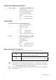
Functions & Installation 2.2 2. Specifications Standard Specifications Item General Specification Rated voltage DC24 V Electric power consumption 6 W or less specifications 1075 g Weight (include EMERGANCY STOP switch and the mode selector key switch, excluding cables) Display specifications Serial interface specifications 2.
Functions & Installation 3. Installation 3. Installation 3.1 Contents TP1 (with cables) Mode selector key 3.2 : 1 unit : 2 units Environmental Conditions The Teach Pendant must be used in an environment that conforms to the following requirements to ensure safe and reliable operation. Item 3.
Functions & Installation 3.4 3. Installation Connection This section indicates the connection of the Controller and the Teach Pendant. Be sure to connect the cables of Controller and Teach Pendant properly. Do not allow unnecessary strain on the cables. (Do not put heavy objects on the cables. Do not bend or pull the cables forcibly.) The unnecessary strain on the cables may result in damage to the cables, disconnection, and/or contact failure.
Functions & Installation 3. Installation NOTE The shape of the cable connector used in connection A and D differs to connection B. TP Cable A : Circular connector to connect to the Operator Panel. (Direct connection is available with conversion kit CK1.) TP Cable B : D-sub connector to connect directly to the Controller. NOTE When Teach Pendant with Operator Panel cable is inserted to the TP port of the Operator Panel, both Operator Panel and Teach Pendant are available.
Functions & Installation 3.5 3. Installation Power Supply The power of the Teach Pendant is supplied via the TP/OP connector on the Controller. After the completing the Controller and the Teach Pendant communication, the following screen will appear on the display of the Teach Pendant. TEACH mode AUTO mode TP1 Rev.
Functions & Installation 3.6 3. Installation Wall Bracket (Option) Outer Dimension [Unit :mm] 201.4 100 J 56.2 226 100 6 31.4 6 Detail : J 6 6 K Detail : K Front View Hook A 118 392.9 39.6 Hook B Back View 16 Side View TP1 Rev.
Functions & Installation 3. Installation Mount and Use Mount the Teach Pendant with the wall bracket in the following procedures. (1) Secure the wall bracket to the wall with three screws (positions are indicated by dotted line in the Outer Dimension). (2) Hang the handle of the Teach Pendant to Hook A. (3) Hang the cable of the Teach Pendant to Hook B. Teach Pendant Cable TP1 Rev.
Functions & Installation 4. Operation Mode (TEACH/AUTO) NOTE 4.1 4. Operation Mode (TEACH/AUTO) A coordinate point including the arm pose is defined as “position (point),” and the data is called “point data.” Outline Robot system has two operation modes TEACH mode and AUTO mode. TEACH mode This mode enables point data teaching and check close from the Robot using the Teach Pendant. Robot operates in Low power status.
Functions & Installation 4.2 4. Operation Mode (TEACH/AUTO) Switch Operation Mode Change the TEACH mode and AUTO mode with the mode selector key switch on the Teach Pendant. TEACH mode AUTO mode TP1 Rev.5 Turn the mode selector key switch to “Teach” for TEACH mode. Pauses the executing program when operation mode is switched to TEACH mode. The operating Robot stops by Quick Pause. Turn the mode selector key switch to “Auto” and change the latch release input signal to ON position for AUTO mode.
Functions & Installation 5. Operation Panel (Key Description) 5. Operation Panel (Key Description) Key Description E-STOP lamp Safety lamp Alphabet and Number Input keys Jog keys Reset key Arrow keys Motor key Home key Cancel key Teaching keys OK key Function keys Alphabet and Number Input Keys Input mode alphabet/number switches by turning ON/OFF the “Alph” lamp. Press the key to turn ON/OFF the “Alph” lamp.
Functions & Installation 5. Operation Panel (Key Description) Arrow Keys Mode switches by turning ON/OFF the “F5-8” lamp. Press the key to turn ON/OFF the “F5-8” lamp.
Functions & Installation 5. Operation Panel (Key Description) Jog Keys Jog key is available only in TEACH mode. Key − + Function Move the target joint (X to W, J1 to J6) to − direction Move the target joint (X to W, J1 to J6) to + direction Teaching Keys Teaching key is available only in TEACH mode.
Functions & Installation 6. 6. Enable Switch Enable Switch In TEACH mode, several operations require use of the 3-position enable switch located on the left rear of the pendant. The enable switch can be operated either hand. When the enable switch is required to execute an operation, you must grip the switch to the center (enable) position. To do this, pull the switch with the left hand fingers until it just stops at the center detent.
Functions & Installation 24 6. Enable Switch TP1 Rev.
Operation This section contains information about operation of the Teach Pendant and maintenance procedure.
Operation 1. 1. Teaching Procedure Teaching Procedure The basic jog operation and teaching procedure is indicated. Switch the mode selector switch to “Teach” to display the following screen. NOTE ) 1.1 A coordinate point including the arm pose is defined as “position (point),” and the data is called “point data.” Jog Operation Move the Robot to the teaching position by one of the following operation (Step Jog operation, Continuous Jog operation).
Operation 1.2 1. Teaching Procedure Teaching Apply the Robot position to the specified point number. (1) Specify the point number by changing the value in the [Point] using the <↑> and <↓> keys. [Label] display changes by changing the point number. (2) Press the key. (3) The following screen appears. When the point number is already used, the following screen appears. (4) Press the key to assign the robot position. (5) Press the key to display the following screen.
Operation 1.3 1. Teaching Procedure Direct Teaching “Direct teach” is a way to teach the Robot directly by setting the teaching joint to servo-OFF. Apply the Robot position to the specified point number. (1) Specify the point number by changing the value in the [Point] using the <↑> and <↓> keys. [Label] display changes by changing the point number. (2) Press the key to select “Free Joint” for the [Jog Dist]. Set each joint to servo ON or OFF.
Operation 1. Teaching Procedure (7) Press the key to display the following screen. Enter the file name and press the key. (8) Press the key to save the file. 30 TP1 Rev.
Operation 2. 2. TEACH Mode TEACH Mode Switch the mode selector key switch to “Teach” to enter the TEACH mode. In this mode, jog, teaching, operation commands, I/O commands, and other operations and commands can be executed using the Teach Pendant. Note, however, that the program cluster cannot be executed. Jog&Teach 2.1 Jog & Teach F1 Point Editor 2.2 Editing Points F2 2.3 Changing the Jog Distance Data Edit Distance F5 F6 Arm/Tool/Local/ECP F4 2.4 Arm / Tool / Local / ECP 2.
Operation 2.1 2. TEACH Mode [Jog & Teach] This section indicates settings in the [Jog&Teach] screen. (1) Switch the mode selector key switch to “Teach” to display the following screen. (2) Set the data items currently displayed in the [Jog&Teach] screen. (See 2.1.1 to 2.1.6.) (3) Note down the robot position. (See 2.1.9.) (4) Back up the point data to a file. (See 2.1.10.) 2.1.1 Specifying Point No. Change the value at [Point] using the <↑> and <↓> keys to specify a point No. Changing the point No.
Operation 2. TEACH Mode 2.1.3 Specifying Jog Speed Press the key and select the speed at [Speed]. (Low, High) Low : Low jog speed High : High jog speed 2.1.4 Executing Step Jog By step jog operation, the robot moves when the Jog key is pressed. Set the distance that the robot moves beforehand. (1) Press the key and select the distance at [Jog Dist].
Operation 2. TEACH Mode 2.1.7 Motor ON/OFF Press the key to switch the motor ON and OFF. TIP ) This can be executed at any time in TEACH mode. 2.1.8 Executing Return to Home Press the key to return the robot to its home position. TIP ) This can be executed at any time in TEACH mode. 2.1.9 Teaching The robot position is assigned to the specified point No. (1) Press the key. (2) The following screen appears.
Operation 2. TEACH Mode 2.1.10 Saving Point Data to File (1) Press the key. (2) The following screen appears. Enter the file name, and press the key. (3) Press the key to save the positions to the file. TIP ) This can also be executed in the [Point Editor] screen. 2.1.11 Loading Point Data from File (1) Press the key. (2) The following screen appears. Move the cursor to select a file. (3) Press the key to load the point data in the file memory.
Operation 2.2 2. TEACH Mode Editing Points This section indicates settings in the [Point Editor] screen. (1) Press the key in the [Jog&Teach] screen. The following screen appears. (2) Set the data items currently displayed in the [Point Editor] screen. (See 2.2.1 to 2.2.4.) (3) Note down the robot position. (See 2.1.9.) (4) Back up the point data to a file. (See 2.1.10.) 2.2.1 Specifying Point No. (1) Specify the point number by changing the value in the [Point] using the <↑> and <↓> keys.
Operation 2.3 2. TEACH Mode Changing Jog Distance Data This section indicates settings in the [Jog Distance] screen. Press the key in the [Jog&Teach] screen. The following screen appears. When a value has been changed, press the key to apply the value, and be sure to press the key to save the settings. 2.3.1 Changing Distance Data Set the distance for each joint.
Operation 2.4 2. TEACH Mode Arm/Tool/Local/ECP This section indicates settings in the [Arm/Tool/Local/ECP] screen. Press the or key in the [Jog&Teach] screen. The following screen appears. When a value has been changed, press the key to apply the value, and be sure to press the key to save the settings. 2.4.1 Changing Arm No. (1) Press the key and move the cursor to [Arm]. (2) Set the arm number. 2.4.2 Changing Tool No.
Operation 2.5 2. TEACH Mode Executing I/O Commands This section indicates settings in the [I/O Command] screen. Press the key in the [Jog&Teach] screen. The following screen appears. 2.5.1 Switching Input/Output Status Display Press the key to switch between the “Inputs” status and the “Outputs” status display. 2.5.2 Output Bit ON/OFF (1) Press the key to display the “Outputs” status. (2) Move the cursor to the output bit that you want to change.
Operation 2.6 2. TEACH Mode Executing Motion Commands 2.6.1 E2 Series / G Series This item indicates the procedure for executing motion commands when using E2 series / G series robots. (1) Press the key in the [Jog&Teach] screen. The following screen appears. Move the cursor to the desired motion command, and press the key. (2) The motion command screen appears. Set the information required for the command, and press the key to apply the settings.
Operation 2.7 2. TEACH Mode Calibrating Origin : E2 Series / G Series This item indicates the procedure to calibrate the origin when using E2 series / G series robots. Follow the procedure below to display the [Calibration] screen. (1) Press the key in the [Jog&Teach] screen (2) The following screen appears. Move the cursor to “0 calibration” and press the key. NOTE ) The following screen appears when the password is set up. Enter the password (1 to 16 characters) and press the key.
Operation 2. TEACH Mode 2.7.1 CAUTION Calibration Procedures (E2 Series) ■ Calibrate Joint #3 first when aligning origins of more than one joint. When Joint #3 is too low, it may collide with peripheral equipment during the calibration of the other joints and may damage the peripheral equipment. The same calibration procedure is used for all joints. Follow the steps below to calibrate each joint. When calibrating Joint #4, you must calibrate Joint #3 and #4 at the same time.
Operation Move the cursor to the joint to calibrate. press the key. 2. TEACH Mode Press the <→> key to select the joint and <→> key : Joint selection <←> key : Joint selection reset The following screen appears when selection Joint #4 and Joint #3 is selected automatically. (4) When a message appears regarding the capacitor charge, leave the power ON for 3 or more minutes to sufficiently charge the capacitor. Press the key to display the following screen. (5) The following screen appears.
Operation 2. TEACH Mode (6) Manually move the joint that needs origin alignment to its approximate 0 pulse position.
Operation (7) Press the key. 2. TEACH Mode The following screen appears. (8) Remove the acrylic panel on the sensor monitor on the base connector plate. Acrylic Panel (9) Set one of the DIP switches (SD1)“1” to “4” corresponding to the calibrating Joint to its ON position. Sensor monitor DIP switch (SD1) Reset switch (SW1) (10) Press and hold the reset switch (SW1) for 1 or more seconds. (11) Press the key to display the following screen. TP1 Rev.
Operation 2. TEACH Mode (12) Turn OFF the DIP switch and mount the acrylic panel on the sensor monitor. Acrylic Panel (13) Press the key. The following screen appears. Press the key again. (14) Controller reboots and the following screen appears. Select one of the currently registered point data that is easy to verify the accuracy of the calibrating joint using the <↑> and <↓> keys, and press the key. Press the key.
Operation (15) The following screen appears. Press the key to turn ON the motor. 2. TEACH Mode Press the key. (16) The following screen appears. Press the key to stop the servo control for all joints to enable the joints to be moved manually. Press the key to display the following screen. (17) The following screen appears. Manually move and position the joint that needs origin alignment while pushing the Joint #3 brake release button and lowering Joint #3. Press the key.
Operation 2. TEACH Mode (18) The following screen appears. Press the key to execute temporary calibration. The following screen appears after executing the temporary calibration. Press the key to servo control all joints. Press the key. (19) The following screen appears. Move the joints except the calibrated joints to the point data position by the motion command. For an example the motion command will be executed to Joint #1 and #2 when Joint #4 is calibrated.
Operation 2. TEACH Mode The following screen appears during Go P1 execution. (20) The following screen appears after Go P1 execution. Set the calibrated joints to the selected point data position accurately by the jog motion. Press the Jog key to move the joint to the basic pose as accurate as possible. Press the key. (21) The following screen appears. TP1 Rev.5 Press the key.
Operation 2. TEACH Mode (22) The origin calibration completed screen appears. NOTE ) CAUTION For righty or lefty setting, refer to 2.7.3 Setting Righty / Lefty. 2.7.2 Calibration Procedures (G Series) ■ Calibrate Joint #3 first when aligning origins of more than one joint. When Joint #3 is too low, it may collide with peripheral equipment during the calibration of the other joints and may damage the peripheral equipment. The same calibration procedure is used for all joints.
Operation 2. TEACH Mode (3) The following screen appears. Move the cursor to the joint to calibrate. press the key. Press the <→> key to select the joint and <→> key : Joint selection <←> key : Joint selection reset The following screen appears when selection Joint #4 and Joint #3 is selected automatically. (4) The following screen appears. TP1 Rev.
Operation 2. TEACH Mode (5) Manually move the joint that needs origin alignment to its approximate 0 pulse position.
Operation (6) Press the key. The following screen appears. 2. TEACH Mode Press the key again. (7) Controller reboots and the following screen appears. Select one of the currently registered point data that is easy to verify the accuracy of the calibrating joint using the <↑> and <↓> keys, and press the key. Press the key. NOTE ) The Manipulator does not move to the exact point because the specified origin is determined visually.
Operation 2. TEACH Mode (9) The following screen appears. Press the key to stop the servo control for all joints to enable the joints to be moved manually. Press the key to display the following screen. (10) The following screen appears. Manually move and position the joint that needs origin alignment while pushing the Joint #3 brake release button and lowering Joint #3. Press the key. (11) The following screen appears. 54 Press the key to execute temporary calibration. TP1 Rev.
Operation 2. TEACH Mode The following screen appears after executing the temporary calibration. Press the key to servo control all joints. Press the key. (12) The following screen appears. Move the joints except the calibrated joints to the point data position by the motion command. For an example the motion command will be executed to Joint #1 and #2 when Joint #4 is calibrated. Press the key while gripping the enable switch to execute Go P1.
Operation 2. TEACH Mode (13) The following screen appears after Go P1 execution. Set the calibrated joints to the selected point data position accurately by the jog motion. Press the Jog key to move the joint to the basic pose as accurate as possible. Press the key. (14) The following screen appears. Press the key. (15) The origin calibration completed screen appears. NOTE ) 56 For righty or lefty setting, refer to 2.7.3 Setting Righty / Lefty. TP1 Rev.
Operation 2.7.3 2. TEACH Mode Setting Righty / Lefty (E2 Series / G Sereis) (1) In the [Calibration] screen, move the cursor to “Righty/Lefty”, and press the key. (2) The following screen appears. Select one of the point data in the accessible area that is easy to verify the accuracy for both right and left arm orientations using the <↑> and <↓> keys and press the key. Press the key. (3) The following screen appears. Press the key. TP1 Rev.
Operation 2. TEACH Mode (4) Continue to press the key with the enable switch held down to execute Jump P1. The following screen appears during Jump P1 execution. (5) The following screen appears after Jump P1 execution. Press the key. (6) The following screen appears. Switch the arm orientation between right and left and move to the same point. Press the key while gripping the enable switch to execute Jump P1. 58 TP1 Rev.
Operation 2. TEACH Mode The following screen appears during Jump P1. (7) The following screen appears after executing Jump P1. Set the calibrated joints to the basic pose accurately by the jog key. Press the key. (8) The following screen appears. Press the key. (9) The origin calibration completed screen appears. TP1 Rev.
Operation 2.8 2. TEACH Mode Calibrating Origin : PS Series This section indicates the procedure to calibrate the origin when using PS series robots. The same calibration procedure is used for all joints. Follow the steps below to calibrate each joint. When calibrating Joint #5, you must calibrate Joint #5 and #6 at the same time. You cannot calibrate Joint #5 alone because of the structure of the Manipulator. (1) Press the key in the [Jog&Teach] screen. (2) The following screen appears.
Operation 2. TEACH Mode (4) The following screen appears. Move the cursor to the joint to calibrate. Press the <→> key to select the joint and press the key. <→> key : Joint selection <←> key : Joint selection reset The following screen appears when selecting Joint #5 and Joint #6 is selected automatically. (5) The following screen appears. TP1 Rev.5 Press the key.
Operation 2. TEACH Mode (6) The Controller reboots and the following screen appears. Press the key to turn ON the motor. Press the key. (7) The following screen appears. Press the Jog key and move the joint close to 0 pulse. When the joint does not move to 0 pulse, move the joint to the set basic pose marked in Setup & Operation Setting the Basic Pose for Calibration in the Manipulator manual. Press the key. (8) The following screen appears. 62 Press the key. TP1 Rev.
Operation 2. TEACH Mode (9) Select a point data that is easy to verify the accuracy of the joint that needs origin alignment from the currently registered point data using the <↑> and <↓> keys, and press the key. Press the key. (10) The following screen appears. Press the key to turn ON the motor. Press the key. (11) The following screen appears. Press the Jog key to move the joint to the basic pose as accurate as possible. Press the key. TP1 Rev.
Operation 2. TEACH Mode (12) The following screen appears. Press the key to execute temporary calibration. (13) The following screen appears after executing the temporary calibration. Move the joints except the calibrated joints to the point data position by the motion command. For an example the motion command will be executed to Joint #1 to #4 when Joint #5 is calibrated. Press the key while gripping the enable switch to execute Go P0. The following screen appears during Go P0 execution.
Operation 2. TEACH Mode (14) The following screen appears after Go P0 execution. Move the calibrated joints to the selected point data position accurately by the jog motion. For an example, Joint #5 and #6 is the calibrated joints. Press the Jog key to move the joint to the basic pose as accurate as possible. Press the key. (15) The following screen appears. Press the key. (16) The origin calibration completed screen appears. TP1 Rev.
Operation 2.9 2. TEACH Mode Releasing Brake (PS series only) This section indicates the brake ON / OFF switching for each joint. (1) Press the key in the [Jog&Teach] screen. (2) The following screen appears. Move the cursor to “1 Brake” and press the key. The following screen appears when the password is set up. Enter the password (1 to 16 characters) and press the key. For password setting, refer to Operation 4. Password Setup. (3) The following screen appears. 66 TP1 Rev.
Operation 2. TEACH Mode To turn the brake ON (4) Press the key of the joint whose brake On/Off setting is to be switched. (5) Press the key. The brake is locked. To turn the brake OFF (4) Press the key of the joint whose brake On/Off setting is to be switched. (5) The brake Off confirmation message appears. key. Confirm the message and press the (6) The brake is released, and the specified joint moves manually. TP1 Rev.
Operation 3. 3. AUTO Mode AUTO Mode Switch the mode selector key switch to “Auto” to enter the AUTO mode. In this mode, jog, teaching, operation commands, I/O commands, and other operations and commands can be executed using the teaching pendant. Note, however, that the program cluster cannot be executed. Auto Mode Print Panel 3.1 Program Command I/O monitor 3.2 I/O Monitor 3.3 Memory I/O Monitor Memory I/O monitor 3.4 Task Monitor Tasks System history 3.5 System History Program mode 3.
Operation 3. AUTO Mode Switch the mode selector key switch to “Auto” to display the [Print] screen. Follow the description on the screen and press the key to display the [Main Menu] screen. TIP ) TP1 Rev.5 Menus with “...” at the end have following procedures after selecting the menu and cannot be executed only by pressing the key.
Operation 3.1 3. AUTO Mode Program Command Display This screen displays messages from the program and requests responses. The [Print] screen appears when the mode selector key switch is switched to “Auto”. To display the [Print] screen from the [Main Menu] screen, move the cursor to [Print Panel], and press the key. When only a message appears Program Example : PRINT #24,“Test Print” The [Main Menu] screen appears.
Operation 3.2 3. AUTO Mode I/O Monitor This screen displays the bit status of I/O. In the [Main Menu] screen, move the cursor to [1 I/O Monitor], and press the key. I/O status (Inputs, bit units) “*” (asterisk) is displayed before the label name for remote setting display to separate remote setting and I/O label. Switches between Inputs and Outputs. Switches the I/O bit status display (Bit units or port units). 3.3 Memory I/O Monitor This screen displays the bit status of memory I/O.
Operation 3.4 3. AUTO Mode Task Monitor This screen displays the status of tasks. In the [Main Menu] screen, move the cursor to [3 Task Monitor], and press the key. When the task name is too long to display the whole name, a tilde is attached at the end of the task name as “LongTaskNa~”. When the task is “NoPause task”, “*P” is attached at the end of the task name. When the task is “NoEmgAbort task”, “*E” is attached at the end of the task name.
Operation 3.5 3. AUTO Mode System History This screen displays a history of errors, operations and warnings that occurred in the past. In the [Main Menu] screen, move the cursor to [4 System History], and press the key. Displays the item type, Number, joint #, task #, date, and time in this order from the left. [System History] main screen Displays the details of the error specified by the cursor. TP1 Rev.
Operation 3.6 3. AUTO Mode Program Mode This section indicates settings in the [Program Mode] screen. Follow the procedure below to display the [Program Mode] screen. (1) In the [Main Menu] screen, move the cursor to [5 Program Mode...], and press the key. (2) The following screen appears. [Program Mode] screen Move the cursor to the last line and press the <↓> key to display the following screen. [Program Mode] screen (next screen) TIP Menus with “...
Operation 3.6.1 3. AUTO Mode Open Programs (1) In the [Program Mode] screen, move the cursor to [0 Open Program...], and press the key. The screen that appears next differs according to the number of files that are currently saved. When there is only one file Select the “function” and press the key to open the file. When there are two or more files Select the file, and press the key to open the file. (2) The following screen appears. Program edit screen (example) TP1 Rev.
Operation 3. AUTO Mode Entering programs The character and numerical value input modes are switched according to whether the “Alph” lamp is ON or OFF. Press the key to switch “Alph” between ON or OFF. Alph OFF Mode Key Numerical value input mode ON Character input mode 0 to 9 − (minus) .
Operation 3. AUTO Mode (3) Enter “170”. Press the key to turn “Alph” OFF. Press the key once. Press the key once. Press the key once. How to enter symbols (1) Press the key to light “Alph”. (2) Press the key to display the following screen. (3) Select the symbol, and press the key. Entering text using key words Candidate command statements are anticipated and displayed from text that is currently being entered.
Operation 3. AUTO Mode Save programs Save programs after editing the programs. (1) Press the key to save the program file. saving the program file. The following screen appears during (2) After the save ends, the screen returns to the program edit screen. Exiting program edit Finish editing the program. (1) Press the key to exit the program file. (2) After the save ends, the screen returns to the program edit screen.
Operation 3. AUTO Mode Search character strings Search for character strings in the program. (1) Press the key. The following screen appears. Enter the character string to search, and press the key. <↓> Displays a list of search text strings. Changes the search order (descending, ascending). The following screen appears during the search. (2) If the character string is found, the cursor moves to the start of that character string.
Operation 3. AUTO Mode Jumping to a specified line in the program (1) Move the cursor to “Line”, and press the key. (2) The following screen appears. Enter a numerical value at [Enter line number] to specify the line number. (3) Move the cursor to the specified line. Jumping to a “function” in the program file (1) Move the cursor to [Function], and press the key. (2) The following screen appears. Move the cursor to the desired “function” and press the key.
Operation 3. AUTO Mode 3.6.2 Building Projects Follow the procedure below to build projects. (1) In the [Program Mode] screen, move the cursor to [1 Build Project...], and press the key. Building of the project is started. The following screen appears during execution. (2) When building is successful The following screen appears after the project building is successfully completed. When building fails The error message list appears. Move the cursor to the desired error, and press the key.
Operation 3. AUTO Mode 3.6.3 Backing up Projects Backs up projects to USB memory. (1) Insert the USB memory into the Controller. (2) In the [Program Mode] screen, move the cursor to [2 Backup Project...], and press the key. (3) The following screen appears. Press the key to execute the project backup. Saves the project to the folder “\EpsonRC50\Projects” in the USB memory. When a project of the same name exists in the USB memory, the following screen appears. Overwrites the project.
Operation 3.6.4 3. AUTO Mode Restore Projects Restores projects backed up in USB memory to the Controller. (1) Insert the USB memory into the Controller. (2) In the [Program Mode] screen, move the cursor to [3 Restore Project...], and press the key. (3) The following screen appears. Press the key. (4) The following screen appears. Displays the project list in the folder “\EpsonRC50\Projects” in the USB memory. Move the cursor to the desired project, and press the key.
Operation 3. AUTO Mode 3.6.5 Import Files Imports “Prg”, “Inc” and “Pts” files in the USB memory to projects in the Controller. Only files of the same name as those that exist in projects can be imported. (1) Insert the USB memory into the Controller. (2) In the [Program Mode] screen, move the cursor to [4 Import File...], and press the key. (3) The following screen appears. Move the cursor to the file to import, and press the key.
Operation 3. AUTO Mode 3.6.6 Export Files Exports “Prg”, “Inc” and “Pts” files in projects in the Controller to the USB memory. (1) Insert the USB memory into the Controller. (2) In the [Program Mode] screen, move the cursor to [5 Export File...], and press the key. (3) The following screen appears. Move the cursor to the file to export, and press the key. (4) The following screen appears.
Operation 3. AUTO Mode (6) The following screen appears. Press the key. (7) Executes the file export. When a file of the same name already exists, the following screen appears. 86 Overwrites the file. Moves to the [Program Mode] screen. TP1 Rev.
Operation 3.6.7 3. AUTO Mode Backup System Backs up system files in the Controller to the USB memory. (1) Insert the USB memory into the Controller. (2) In the [Program Mode] screen, move the cursor to [6 System Backup...], and press the key. (3) The following screen appears. Enter the file name and press the key. (4) The following screen appears. Press the key. TIP ) When key is pressed without specifying a folder, the backup file is stored directly in the USB memory.
Operation 3. AUTO Mode (6) The following screen appears. Press the key to execute the system backup. When a file of the same name already exists, the following screen appears. Overwrites the file. Moves to the [Program Mode] screen. (7) After execution is completed, the following screen appears 88 TP1 Rev.
Operation 3.6.8 3. AUTO Mode Restore System Restores system files backed up in USB memory to the Controller. (1) Insert the USB memory into the Controller. (2) In the [Program Mode] screen, move the cursor to [7 System Restore...], and press the key. (3) The following screen appears. When you restore the robot name, serial number, and the calibration data with the basic Controller settings, move the cursor to [Robot name, serial #, calibration] and press the <→> key.
Operation 3. AUTO Mode (7) The following screen appears. Press the key to start the restore. When the Controller serial number does not match the serial number of the selected Controller setting data, the following screen appears. To continue, press the key. When the Controller system software version does not match the version of the selected Controller setting data, the following screen appears. To continue, press the key.
Operation 3. AUTO Mode 3.6.9 Changing Speed Factor Changes the operating speed of robot motion commands (Go, Jump, Pulse commands, etc.) in the program. (1) In the [Program Mode] screen, move the cursor to [8 Speed Factor...], and press the key. (2) The following screen appears. Enter the factor (unit: %, 1 to 100 integer) with respect to the maximum speed. Press the key and apply the numerical value. Returns the factor to its default (100). (3) Press the key to set the value.
Operation 3. AUTO Mode Configure program editor Set the preferences of the program editor. (1) In the [Configuration] screen, move the cursor to [0 Editor], and press the key. The setup screen appears. To change an item: Move the cursor to the left column. To change item settings: Move the cursor to the right column. (2) Press the <↑> <↓> keys to move the cursor to the item and press the <→> key to move the cursor to the right to confirm the item.
Operation 3. AUTO Mode Enable execution in main menu Normally, the followings are set in the program mode after the password is entered. - Project Backup / Restore - System Backup / Restore - File Import / Export Items that are enabled for execution are added to the menu in the [Backup] screen. (See “Operation 3.7 Backup / Restore.”) Follow the procedure below to enable execution in the main menu. (1) In the [Configuration] screen, move the cursor to [1 Backup Screen], and press the key.
Operation 3. AUTO Mode (2) The following screen appears. Move the cursor to the desired display language, and press the key. (3) Press the key and the Controller reboots. 3.6.12 Update System Software Updates the system software of the Controller to the system software in USB memory. (1) Insert the USB memory into the Controller. (2) In the [Program Mode] screen, move the cursor to the last line, and press the <↓> key. The following screen appears.
Operation 3. AUTO Mode (4) The following screen appears. Move the cursor to the folder to update, and press the key. Displays the hierarchy one level below the selected folder. Displays the hierarchy one level above the selected folder. (5) The following screen appears. Press the key to execute the update. (6) After the software is updated, the following screen appears. TP1 Rev.
Operation 3.7 3. AUTO Mode Backup / Restore Normally, the following settings are made in the program mode after the password is entered: - Project Backup / Restore - System Backup / Restore - File Import / Export Items that are set as “Yes” (execution in the main menu “enabled”) at “Enabling execution in the main menu” can be set. (1) In the [Main Menu] screen, move the cursor to [6 Backup / Restore...], and press the key. (2) The following screen appears.
Operation 3.8 3. AUTO Mode Save Controller Statuses Indicate the procedure to save the status of the Controller to the USB memory. (1) Insert the USB memory into the Controller. (2) In the [Main Menu] screen, move the cursor to [Controller States...], and press the key. The following screen appears. (3) Select a folder to save the data. The root directory is selected by default. (4) Press the key to save the status. 3.
Operation 3.10 3. AUTO Mode Adjust Brightness and Contrast (1) In the [Main Menu] screen, move the cursor to [9 Brightness / Contrast], and press the key. (2) The following screen appears. <↓><↑> Press the key to apply the setting. These arrow keys can adjust the brightness. <←><→> These arrow keys can adjust the contrast. 3.11 Error Messages The following screen appears when an error occurs. 98 Moves to the [Main Menu]. Moves to the screen before the error occurred.
Operation 4. 4. Password Setup Password Setup Setup a password to limit operators for the following menu. TEACH mode ........ [Jog&Teach]-[Maintenance] AUTO mode .......... [Main Menu]-[Program Mode...] Follow the procedure below to set the password. (1) Turn ON the Controller. (2) Double click the icon on the desktop. (3) Select EPSON RC+5.0 menu-[Setup]-[Controller]-[Configuration] to display the following page. (4) Click the button at “TP Program Mode Password.
Operation 5. 5. Troubleshooting Troubleshooting Display panel is blank - The Controller supplies DC24V. Check that the Controller is ON. - Check that the Controller is connected to the TP/OP connector of the Controller properly. An Error code appears and the Robot does not operate normally - Please refer to the error code indicated in the Controller manual. Robot does not move by pressing the Jog key - Execute the Motor On command to energize the Robot motor.
Operation 6. 6. Maintenance Parts List and Option Maintenance Parts List and Option Be sure to specify the proper codes and Option when ordering maintenance parts. Part Name Rev.
Operation 102 6. Maintenance Parts List and Option TP1 Rev.