XK3190 C 602 XK3190-C602 Weighing Indicator User Manual 襦Version 1.
XK3190 C 602 Content Preface Chapter 1 General…………………………………………………… Chapter 2 Main Parameters…………………………………………… Chapter 3 Installation, Interface & Communication Format………… Chapter 4 Parameters Setting and Calibration………………………… Chapter 5 Operating Instruction of Quantitative Scale………………… Chapter 6 Control Process of Quantitative Scale ……………………… Chapter 7 Operating Instruction of Catchweigher…………………………… Chapter 8 Application Examples of Catchweigher…………………………… Annex A Error Prompt Message…………………………………………… An
XK3190 C 602 Preface Instruction for use of manual This manual is for reference by the operators and installers of XK3190-C602 indicator during their operation or installation and testing. Chapter 1 and chapter 2 of this manual introduce the technological features and parameters of the indicator in a general manner.
XK3190 C 602 air and has not reached to the load carrier. To obtain the predetermined material weight, it is necessary to turn off the feeder in advance. The weight involved in the leading is called a lead. For C602, “self-correction of lead” function can be activated to ensure the accuracy of final weight.
XK3190 C 602 the captured object weight. Initial zero-setting is the first zero-setting operation after startup. It can be set as automatic zero-setting upon startup (initial) or manual zero-setting. If zero-setting upon startup is prohibited, the indicator maintains the zero point at shutdown. The initial zero-setting range can be selected and generally ±10%Max is set. If the variation of zero point of scale exceeds the initial zero-setting range, initial zero-setting cannot be carried out.
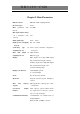
XK3190 C 602 Chapter 1 General The XK3190-C602 weighing indicator adopts Cortex M3 32-bit processor and high-precision 1- A/D convertor to carry out conversion display for weight signal. The maximum conversion speed can reach up to 200/s. The display can be easily connected with resistance strain gauge transducer to form batching scale and quantitative packing scale etc., suitable for various applications where high-speed and high-precision weighing control are required.
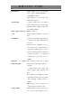
XK3190 C 602 Chapter 2 Main Parameters Indicator model XK3190—C602 weighing indicator Precision degree Level 3 Max. verification scale nind=3000 interval Min. input signal voltage of e verification scale 12V interval Input signal range 3mV 15mV Bridge power of weighing DC 5V 80mA load cell Connecting type of of long wire weighing load cell Max. cable 6-wire system, automatic compensation length of 100m / 0.
XK3190 C 602 Parallel output port: to be connected with Print interface micro printer, LT800, KX-P1121 or LQ1600K line printers. Serial interface: to be connected with serial interface printer 8 optical isolation and open collector Switch output switch output with max. control voltage 330V DC, current 3100mA, total current of 8 channels 3200mA Relay output (with relay Number of relay: 8 Contact capacity: 220VAC / 28V DC box) 0.
XK3190 C 602 0-10V. Precision degree 30.2%FS Load capacity: 4-20mA max. load resistor 2504 0-5V / 0-10V output impedance 3 14 Working power supply 110 230V AC 50/60 Hz Temperature 0 humidity of and 40 390 RH -20 50 390 RH working environment Temperature humidity transportation and of and storage External dimension Housing: 150 * 75 * 105 (mm) (width * height * depth) Panel: 172 * 93 * 3 (mm) (width * height* thickness) Dimension of installation hole: 152 * 77 (mm) Weight About 0.
XK3190 C 602 Chapter 3 Installation, Interface & Communication Format I.
XK3190 Connecting terminal of power C 602 Connecting terminal of switch output Connection terminal of switch Connection terminal of analogue output Connection terminal Calibration Connecting switch terminal of Interface of parallel printer Figure 3 2 Schematic Diagram of Back Panel of weighing load cell
XK3190 C 602 II.
XK3190 C 602 Inter-panel High voltage area connector in power panel Setting jumper of analogue output Figure 3-4 Schematic Diagram of Power Panel
XK3190 C 602 Attention: the indicator shall have sound and reliable earthing protection so as to ensure the operation stability and safety of operator. Installation method of indicator Unscrew two M4 fastening screws on both sides at back of the indicator, remove the binding, insert the indicator into the installation hole, insert the binding again and fasten it with M4 screws.
XK3190 C 602 III. Connection between load cell and indicator 1. 7-pin electrical male plug are adopted for connection of load cell. Figure 3-5 shows the meanings of each pin. 2. When junction box is used to connect several load cells or extend the cable of load cell, six-wire connecting method must be adopted. When 1 load cell is used and the cable is not extended, four-wire system can be adopted. Under this condition, it is necessary to short connect the EX+ and SEN+ with EX- and SEN- respectively. 3.
XK3190 C 602 IV. Printer interface 1. Parallel printer interface adopts the standard 25-pin D type jack socket. Figure 3-6 shows the meaning of each pin. The indicator can be connected to printer by standard parallel interface printer cable. The 13th pin is +5V output which can be used to connect micro printer with peak current below 2A.
XK3190 C 602 V. Scoreboard display interface The scoreboard display interface is the 20mA current loop interface which is capable of driving various scoreboards. Please refer to appendix C for the data format and oscillograph of scoreboard display interface. In the figure, DP+ and DP- are the 20mA current loop interface of scoreboard. Figure 3 7 Serial Communication and Scoreboard Display Interface VI.
XK3190 C 602 in which the right RxD and TxD are RS-232 (2) interface while the TXD0, TXD1, XD0, and RXD1 are RS422/485 interface. Only one of the two can be selected in operation. If terminating resistance and pull-up resistance or pull-down resistance needs to be connected, open the housing, draw out main panel, and short jumper JP3 in main panel.
XK3190 12 0x0A C 602 Linefeed sign For instance, if the indicator measures a gross weight of 50.00 (kg), it will send data as follows: “G 50.00”; If the indicator measures a net weight of “N 0.040 (kg), it will send data as follows: 0.040”. 2. Command response mode When SET 1 parameter 6B is set as 0 or 2, the serial interface 2 works in command response mode.
XK3190 C 602 VIII. Control interface and indicating lamp See figure 3-8 for optical isolation switching value interface. O0 ~ O7 are the switch output signal terminals for the 8 open collectors, with each terminal absorbs current 100mA at maximum and the total current shall not exceed 200mA. I0 ~ I7 are the 8 Switch input signal terminals. 0V and +12V are the connecting terminals for 12V external isolation power supply, with maximum capacity of power supply of 200mA.
XK3190 C 602 S S C C C C C O S S S S E S Oper t t h h h h h p ta t ta t x t ation a a a a a a a e n a n a te o n n n n n n n r d n d n r p Definition of d d n n n n n a b d b d n catch- b b el e el e el ti y b y b al weigher y y 5 l 3 l 1 o y c terminal 4 2 y n Standby o n tr o l Corresponding O7 O6 O5 O4 O3 O2 O1 O0 I7 I6 I5 I4 I3 I2 I1 I0 indicating lamp on panel Figure 3-8 Switch input and
XK3190 C 602 Figure 3-9 Setting of Analog Output Calibration method of Analog output The zero point value and full range value of analog quantity are proportional to the corresponding DA code (see table 4-3, explanation for SET 1 parameter 11 and 12). Calculation and calibration of parameter 11 and 12 can be done by using the tolerance of Analog output.
XK3190 C 602 Chapter 4 Parameters Setting and Calibration I. Parameters setting The indicator has 5 groups of parameters setting condition, which are as follows: SET 0 : inquiry parameters; SET 1 :general parameters; SET 2 : control parameters; SET 3 : calibration; SET 4 : calibration parameters. Press setting then press input button to enter [ [SEt 0] , press ] 5 or 6 to select the parameter group, button to enter the setting of relevant parameter.
XK3190 C 602 next parameter. In the following parameters, the italic letters “ABCDEF” in “indicator display” represent that the indicator displays the values of parameters A, B, C, D, E, and F at the same time. “*”, “**”, “******”, and “**.**.**” represent that it only displays the value of one parameter. The lower line in the indicator display shows the DOS prompt. In the DOS prompt, letter M is displayed as “ ”, and letter W is displayed as “ “.
XK3190 C 602 4 The same as the above Display of accumulative weight: when the effective value is above 6 digits, the digits of decimal will Accumulated weight automatically reduce. A—printing option [******] (0: no printing, 1: printing When the integer is [A A] accumulative data, 2: printing all above 6 digits, it can data in memory) only display 6 digits; the number of left decimal points which are lit on represents the number of digits not displayed.
XK3190 C 602 Table 4-1 SET 0 Parameter Table of Catchweigher (When Para mete r Indicator display SET 1 parameter 13A selects 2 or 3 in table 4-3) 1 [**.**.**] Current date setting [dAtE ] 2 [**.**.**] Current time setting [tIME ] 3 4 5 [ ****] [n A] [******] Total accumulated weight [A A] [ ****] Accumulated times of channel Not to be modified, only [n1 A] 1 for inquiry.
XK3190 C 602 can also return to “0” content code status. Display of accumulative B—content in auxiliary display weight: when the B 0 1 2 3 4 5 effective value is above 6 digits, the decimal digits will automatically reduce. When the integer Displa accum Worki Note accum is above 6 digits, it can yed ulated ng 1 ulated Date Time only display 6 digits; the conte weigh step Note times number of left decimal nt t note 1 2 points which are lit on represents the number of digits not displayed.
XK3190 SET 1 C 602 general parameters Table 4-3 Table for Setting of General Parameters Param Indicator display eter 1 [ABCDEF] [COMM ] Parameter explanation Remarks Hardware selection A communication (1) (0: communication (1) OFF, 1: communication (1) ON) B communication (2) (0: communication (2) OFF, 1: communication (2) ON) C scoreboard (0: scoreboard 1 OFF: scoreboard ON ) D printer (0: printer OFF, 1: printer ON) E analog quantity (0: Analog output OFF, 1: Analog output ON) F display of analog
XK3190 C 602 A little Mediu A little C Filter Weak Strong weak 4 [ **] [Addr ] m strong Indicator communication address (01 ~ 26) When several indicators communicate with PC through the RS422/485 bus, communication addresses can be used to distinguish them. Communication baud rate (0 ~7) A-communication interface B-communication interface (2) 5 [ AB] [bAud ] 0 1 2 3 BPS 600 1200 2400 4800 A,B 4 5 6 — BPS 9600 19.2k 57.
XK3190 8 9 10 11 12 13 14 C 602 [ AB] [PL ] Parameter B is only effective A—selection of printing language for micro printer. As for (0: English; 1: Chinese) panel-installed micro printer, B—printing direction selecting reverse printing is (0: no reverse printing, 1: reverse printing) easy for checking printing result.
XK3190 C 602 Note 1: if parameter 9 B is set as 1, while meeting the condition for automatic printing, it will save weight data, with 8064 weighing times as maximum. If 2 is selected, while meeting the condition for automatic printing, it will also save the current time and weight data, with 4032 weighing times and weight data as maximum. If the memory is full, the new data will overlap the earliest ones. When summation is deleted, the recorded data is also deleted.
XK3190 C 602 SET 2 control parameters Refer to table 4-4 and 4-5 according to different value of SET 1 parameter 13A.
XK3190 C 602 1. The discharge is deemed over when the indicator shows the gross weight is below zero zone. 2. The indicator can print and sum only when the gross weight is above zero zone. 11 [******] [0_Zone] Zero zone 12 [ ***] [t0 ] Avoid misjudgment of weight Feed measuring delay (0.0 ~ 25.5 caused by the weight impact at seconds) startup 13 [ ***] [t1 ] Measurement delay of quick feed When t1 = 0, quick feed and slow over (0.0 ~ 25.5 seconds) quick are activated at same time.
XK3190 C 602 Table 4-5 Parameter 2 of Catchweigher (when Para Indicator mete display r SET 1 parameter 13A is set as 2 or 3 in table 4-3) Parameter explanation Remarks 1 A—catchweighing mode [ A] (0: non-peak hold, 1: peak [CtrL ] hold) 2 Upper limit of channel 1: Refer to note of parameter 8 [******] If “zero zone” 3X A, the for meaning of X. Same for [A ] indicator outputs signal of below. channel 1 at t3.
XK3190 C 602 7 Judgment delay (0 ~ 25.5) seconds: Under external control mode, when it is activated, data Please refer to parameter 6 [ ***] calculation is started after for the definition of “zero [t0 ] t0; zone”. Under self-control mode, data calculation is started after t0 when weight is out of zero zone. 8 Time for calculation of average weight (0 ~ 25.5) seconds: After t0, the indicator will Assume that the obtained [ ***] sum the weight values and [t1 ] value is X.
XK3190 C 602 the calibration is valid. Toggle the switch to ‘ON’, press the button [ ] [CALIb ] is shown. Press the calibration status. Press Input Setting and press and the indicator will show 5 or [ [SEt 6 repeatedly until 3] , which means it is ] Input again to start the calibration process. Please see the following table for the calibration instruction and operation method (* is the original setting value).
XK3190 8 [******] Display [CALEnd weight ] current C 602 The calibration is done and the calibration status is Toggle the load quitted. calibration switch to OFF and press Input to go back to normal weighing status. III. Checking of calibration data Prompt: The calibration switch should be opened when the calibration data is modified, otherwise it cannot be saved. Press Setting and 6 [ 4] to show [SEt ] . Press Input , the indicator will enter the data checking status, please see table 4-7.
XK3190 8 9 Current Zero [******] (Relative to [0Point] zero) [ C 602 Cannot be modified. This parameter reflects calibration the zero stability of weighing load cell. A—Whether to print each A] parameter [Print?] 0 No 1 Yes Note 1: Nonlinear correction uses the parabola calculation method. The correction value is 1/2 max. weighing position, that is, the correction amount at the top of the correction curve. Nonlinear correction value equals to the negative value of the nonlinear tolerance of 1/2 max.
XK3190 C 602 Chapter 5 Operating Instruction of Quantitative Scale I. Startup and zero setting upon startup 1. After power is connected, the screen will full display for 10 seconds and show the indicator type and software version, then finally enter the weighing status. If the button Exit is pressed halfway, then automatic checking will be ended in advance. 2.
XK3190 V. C 602 Print Print Print the current weight under non operating, non setting status . Remark: Please confirm the parameter setting of the printer type before printing to avoid printing mistake. VI. Data Query and Removal Method to Save Weighing Data Set Parameter B in Parameter 9 [ AB] of [Auto P] SET 1 as 1, the quantitative scale will automatically save the actual weight of each quantitative cycle.
XK3190 C 602 to the running status and continue its work. If the button Stop is pressed repeatedly, the indicator will be switched over between ‘pre-stop’ and ‘pause’; Press button Setting under ‘pause’ status to enter the status of stop, and the status before ‘pause’ will not be saved. The valid signal (i.e. add voltage of 12V~24V or short connected to ‘+12V’) are input to terminal ‘function’ Operation or I1 ,’stop’ I2 on the rear panel, which has same function as button Stop .
XK3190 C 602 with long duration is executed (for example, print the weighing record), the button pressed during the command execution period will be stored in the buffer area of key command. The new key command will be responded only when the current key command is executed.
XK3190 C 602 Chapter 6 Control Process of Quantitative Scale I.
XK3190 C 602 4. If the Add Signal and Discharge Signal are always valid, the indicator will automatically execute the procedure repeatedly. Table 6-2 describes the working process of quantitative scale subtraction by program step. Display method of program step Set Parameter 7B of SET 0 to 4; under running status, the auxiliary display of the indicator will show the current program step number in forms of ‘Step**’.
XK3190 C 602 of material 1 and the gradual feed is allowed, go to program step 7 and the timer will be T3; If the gradual feed is not allowed and the weight is more than the batching value plus tolerance, out-of -tolerance treatment will stop at this step and wait for qualified out-of-tolerance treatment. If the out-of-tolerance treatment is not done, then go to program step 9, the timer will be T5. 7 Start the slow feed of material 1.
XK3190 C 602 is less than the batching value of material 1 minus tolerance of material 1 and the gradual feed is allowed, go to program step 16 and the timer will be T3; If the gradual feed is not allowed and the weight is more than the batching value plus tolerance, out-of-tolerance treatment will stop at this step and wait for qualified tolerance treatment. If the out-of-tolerance treatment is not done, go to program step 18, the timer will be T5.
XK3190 C 602 Subtracting scale is to control the material (i.e. the material feed) weight discharged by the control hopper.
XK3190 C 602 execute the procedure repeatedly. 4. If the remaining material weight is less than the min. weight (i.e.d1+d2) of one time material feeding weight plus material in the hopper, the instrument will be stopped to do the material feeding and wait for the Add Signal (it means material charging is allowed, that is, feed material to the hopper); The output control signal of material discharging of the instrument will be valid after there is an Add Signal and it will start to judge the weight.
XK3190 C 602 off quick feed. The timer will be T1 and go to program step 3. 3 The timing is over, go to program step 4 and the timer will be T0. 4 Start the slow feed; timing is over and weight inspection is started. If the loaded value reaches to batching value minus slow feed lead, turn off slow feed. Timer will be T2 and go to program step 5. 5 The timing is over. If the lead correction is allowed, modify the slow feed lead and go to program step 6.
XK3190 C 602 program step 1. Otherwise stop the action. 13 If there is an Add Signal, go to program step 14. 14 Start the material discharging, add material to the hopper until the allowed weight is reached and go to program step 15. 15 If the material discharging is started manually, then stop the action. Otherwise go to program step 16 and the timer will be T6.
XK3190 C 602 Chapter 7 Operation Instruction of Batching scale I. Power on and Zero Setting upon Start up 1. After power is on, the screen will full display 10 seconds and show the instrument type and software version, then finally enter the weighing status. If the button Exit is pressed during automatic checking, it will be ended in advance. 2.
XK3190 Setting 8 Input C 602 date setting 8 Input time setting V. Printing Print Print the current weight in non-operating, non-setting status . Remark: Please confirm the type of printer before printing to avoid printing mistake. VI. Data Query and Removal Method to Save Weighing Data Set Parameter B in Parameter 9 [ AB] [Auto P]of SET 1 to 1, the batching scale will automatically save the actual result of each weighing.
XK3190 C 602 status or exit running status. After it is started, O0 will output the running signal to control the function of devices such as conveyer belt. When the functioning status is entered, any other buttons will not respond except the button Stop . Add the voltage 12V~24V to the input terminal ‘operation’ I1 , ‘stop’ I2 on the rear panel or short connect them to the voltage ‘+12V’, which has the same function as the button Operation or Stop .
XK3190 C 602 Chapter 8 Application Examples of Batching scale I. Self Control Mode If belt weighing scale is provided at the control site, the user has to choose three different cargoes of different weights through the belt. The weights of these three cargos are respectively 5kg, 10kg and 15kg and it will be delivered through the belt every 10 seconds.
XK3190 C 602 Fig 8-1 Time Sequence of Catchweigher in Self-control Mode Brief introduction of control procedure of batching scale in self-control mode (Please refer to the sequence order figure): (1) The instrument starts to run and it will judge whether the weight is higher than zero zone.
XK3190 C 602 the auxiliary display of the instrument will show the current program step number in forms of ‘Step**’. Table 8-2 Description of Program Steps of Self-control Mode Program Description Step If the net weight value is more than upper limit of zero zone, go to 1 program step 2 and timer will be T0. Timing T0 is over. Start to calculate the average weight and go to 2 program step 2, timer will be T1. Record the weight data. Timing of T1 is over.
XK3190 C 602 II. External Control mode Suppose high speed batching scale is provided at site: Industrial control PLC will combine with the instrument to sort out the cargos quickly. PLC will control the cargo to the weighing platform. A signal will be triggered to the instrument after the cargo is loaded to make the weighing platform calculate the weight. The weight scope of the users’ qualified product is 9.90kg ~ 10.
XK3190 [d ] C 602 to the max. value. Please refer to Fig 8-2 for the control sequence order of batching scale in external mode.
XK3190 C 602 Display method of program step Set Parameter 17B of SET 0 to 4. Under running status, the auxiliary display of the instrument will show the current program step number in forms of ‘Step**’. Table 8-4 Description of Program Step in External Control Mode Program Description Step If the external signal I3 is valid, go to program step 2 and the timer 1 will be T0. Timing T0 is over. Start to calculate the average weight, go to 2 program step 2 and the timer will be T1. Record the weight record.
XK3190 C 602 Annex A Error Prompt Message Table A-1 Error Prompt Message Explanation Error Prompt Message Explanation Handling method [Error ] [ 1] Tare requirement is not met. Tare after getting stable. [Error ] [ 2] Requirement of zero-setting is not met. Set zero stable. [Error ] [ 3] Input parameter allowed range. Input the correctly. [Error ] [ 4] EEPROM damaged is Replace U15, U16 on main board [Error ] [ 5] Calibration data is wrong, and the parameter is initialized.
XK3190 [ 10X] C 602 wrong U15, U16 hardware damaged or not installed U16 on main board is [Error ] [ 110] Error occurs during weighing record saving. Ditto [------] [XXXXXX] Calibration parameter is not appropriate, causing weight indication value exceeding indication scope of indicator Recalibrate correctly, and set appropriate parameters.
XK3190 Annex B Output Quantitative scale C 602 Schematic Diagram of Relay Board O0 Zero point O1 O2 O3 Slow Fast 1 Fast 2 1 Channel Channel Channel Catchweigher Operation 1 2 3 O4 O5 O6 Slow Feed Eligible 2 Channel Channel Stand-by 4 5 O7 Out-of-tolerance Stand-by Figure B-1 Definition of Output Function of XK3190-C602 Relay Box During installation, connect the cable coupled with relay J1 terminal to output terminal block of C602 instrument, i.e.
XK3190 C 602 Annex C Large Screen Data Waveform Graph and Format 1. C602 instrument can be connected with all kinds of large screen display. 2. Large screen display interface is provided with 15 core connector assembly, (sharing a socket with serial communication interface), the definition of its pin can be seen in description of pin 9, 10 in Figure 3-4. 3. Scoreboard signal is current loop signal of 20mA constant current, serial output in binary code, with baud rate of 600.
XK3190 Figure C C 602 Signal Format of Scoreboard Display Interface
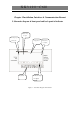
XK3190 C 602 Annex D Data Format of Communication Port (1) During work mode selection of communication port 1 (setting 1, step parameter), it transmits data to PC once after each time of AD sampling. Mode 0: transmit AD code continuously Baud rate of communication should be more than “AD conversion rate * 60”, or otherwise unrecognized characters or data loss may occur.
XK3190 C 602 Annex E Data Format of Command-Response Mode of Communication Port (2) Data format for communication of response mode: Table E-1 Data Format of Communication Field Start signal Length Address Command NN ****** Check (optional) (optional) sum End signal 1 1 1~2 2 1~12 2 1 Indication hexadecimal ASCII ASCII ASCII ASCII ASCII hexadecimal form system character character character character character system Content 02H A~Z See table Note: 1 D-2 Note Note
XK3190 Send by instrument sent B by PC Send C by by PC Send by instrument Send D by PC Send E by by PC Send by instrument Send F by PC Send by instrument Send G by PC Send by instrument Send by PC Send gross weight Read net weight Send gross weight Read tare Send tare weight Tare Tare Zero-setting Zero-setting Operate Operate Stop H Send by instrument Send I by PC Send by instrument Send J by PC Send by instrument K Send PC 02H AA00 03H 02H Addr B XH XL 03H
XK3190 C 602 02H Addr K XH XL 03H Send by instrument 02H AK0A 03H the instrument enters Pause/Continue into pause or running state Send L by PC Send by instrument Send M by PC Send by instrument Send N PC Send O by Accumulate Print Print Print by Print accumulation Send Print working by PC by by PC Send by by PC Print working 02H Addr L XH XL 03H 02H AL0D 03H 02H Addr M XH XL 02H AM0C 03H 03H 02H Addr M XH XL 02H AM0C 03H 03H 02H Addr N XH XL 03H 02H AN0F 03H 02H
XK3190 Send by PC Write calibration by instrument Send 02H Addr T NN ****** XH XL 03H by PC Return to calibration parameter U 02H Addr T NN ****** XH XL 03H AT NN ****** Return to PC command 02H Addr U NN ****** 02H XH XL 03H 03H AU NN ****** Refer to Note 3 by Return to working XH XL 03H instrument 02H 03H 02H Addr U NN ****** Send AT NN ****** Refer to note 2, note 5.
XK3190 Send AC by PC by instrument Send by Addr AC NN 02H AACO0013D 03H ****** XH XL 03H 02H Send IO state Addr AC NN 02H ****** XH XL 03H AACO0013D 03H Read internal 02H Addr AD NN XH 02H AAD J13F memory state XL 03H by Send internal 02H instrument memory state ****** XH XL 03H Send Write internal 02H PC Send AE 02H Send IO state Note 9 Send AD C 602 by PC memory Send Note 10 Addr Addr AD AE Send internal 02H instrument memory state ****** XH XL 03H Send
XK3190 C 602 zero) AQNL 000.000 1C Non-linear modification value 0 AQAD 2 27 AD transfer speed 2 AQFL 2 28 Filtration strength 2 AQFm 1 0A Filtration method 1 AQSt 2 05 Stable judgment 2 AQ0T 1 45 Zero tracking range 1 AQ0S 1 42 Zero setting range 1 AQ0I 4 5D Initial zero setting range 4 20% AQEI 1 2D Initial zero setting switch 1 on AQUt 2 03 Weight unit 2 Note 3 of Table E-2: 60cps 0.
XK3190 C 602 ARPr 3 02 Printer type 3 ARPL 1 3E Printing language 1: Chinese AR1C 1 50 Work mode 1 of serial port 1: send weight continuously AR2C 2 50 Work mode 2 of serial port 2: RS485 mode AR1B 4 54 Baud rate 4 of serial port 1: 9600bps AR2B 4 57 Work mode 4 of serial port 2: 9600bps ARAo 020.000 31 Relevant weight of full measuring range of analog output 20.
XK3190 C 602 Note 4 of Table E-2: NN=00: read accumulated data, NN=01: read all stored data. Codes of accumulated data of quantitative scale: Tc total times; Tw total weight. Codes of accumulated data of batching scale: Tc total times; Tw total weight; 1C~5C total times of channel 1 ~ channel 5; 1W~5W total weight of channel 1~ channel 5. Format of saved data output: 02H, address, command (S), sequence No.
XK3190 C 602 and data format are same as Note 8 of E-2. Table E-2 Note 10: The meaning of NN parameter is shown in Table E-8. Table E-8 Definition of Parameters Parameter code Definition Remaining time of time relay 0 ~ time relay 7; integer TA~TH of returned 3 bytes of C602 represents calculated value of remaining time. Time unit 100ms, value range 0~255. States of group 0 to group 7 intermediate relays, 8 JA~JH intermediate relays for every group. Group 0 is time relay.
XK3190 C 602 Annex F Explanation on Print Format F.1 Microprint format : F.1.1 Print current weight F.1.1 Print current weight Print in Chinese -----------08/12/07 10:10:31 010.000 kg 001.000 kg 009.000 kg -----------Print in English ---------------Date : 08/12/07 Time : 10:10:31 Gross: 010.000kg Tare : 001.000kg Net : 009.000kg ---------------- F.1.2 Automatic print format (same for grader and quantitative scale) Print in Chinese kg -----------00001 004.999 00002 005.000 00003 005.
XK3190 F.1.3 Accumulated print of quantitative scale Print in Chinese -----------08/12/07 15:04:18 00003 0000014.999kg -----------Print in English Accu -----------Date:08/12/07 Time:15:04:18 No :00003 Total 0000014.999kg ------------ F.1.4 Accumulated print of grader Print in Chinese -----------08/12/07 15:04:18 -----------1 00002 0000003.000 kg 2 00002 0000006.000 kg 3 00000 0000000.000 kg 4 00000 0000000.
XK3190 C 602 5 00000 0000000.000 kg -----------00004 0000009.000 kg Note: the accumulated data of various channels are not saved when de-energized, while the total accumulated value is saved, therefore, after being energized, the total accumulated No, total weight and sum of various channels will be inconsistent if the original total value is not cleared. Print in English -------------Date: 08/12/07 Time: 15:04:18 -------------Ch1 : No: 00002 Tt: 0000003.000 kg Ch2 : No: 00002 Tt: 0000006.
XK3190 C 602 SUM : No: 00004 Tt: 0000009.000 kg F.2 Line printer format F.2.1 Print current weight Print in Chinese 08/12/07 9:14:43 kg 003.000 kg 000.000 kg 003.000 Gross(kg) 003.000 Tare(kg) 000.000 Net(kg) 003.000 Print in English Date 08/12/07 Time 9:14:43 F.2.2 Automatic print (same for accumulative scale and grader) Print in Chinese 08/12/07 00001 00002 00003 09:04:13 09:04:24 09:04:50 kg kg 006.000 006.001 006.000 0000006.000 0000012.001 0000018.
XK3190 C 602 -----------08/12/07 15:04:18 00003 0000014.999kg -----------Print in English Accu -----------Date:08/12/07 Time:15:04:18 No :00003 Total 0000014.999kg ------------ F.2.4 Accumulated print of catchweigher Print in Chinese 08/12/08 09:15:28 kg 1 2 3 4 5 00001 00002 00001 00001 00001 0000001.000 0000006.000 0000005.000 0000007.000 0000007.999 00006 0000028.999 Print in English Date :08/12/08 Time: 09:13:25 Chs : No : Total : kg 1 2 3 4 5 00001 00002 00001 00001 00001 0000001.
XK3190 C 602 printer) There is only English format for parameter print, the explanation is as follows Content of print C602 Ver1.00 Max=: 020.000kg e= : 01 Dp : 03 0_AD: 00262121 0Point: 000.000kg R : 00067106 Line: 000.000%FS COMM:111110 0_SET 141 Flt : 1222 Addr: 01 Buad: 44 Mode: 22 Prnt: 1 PL : 00 AutoP 12 Aout_W 020.000kg Aout_0 00000 Aout_F 65070 Type: 212 Disp: 04 Light: 5 Explanation Instrument type and software version No. Max.
XK3190 C 602 There is only English format for parameter print, with explanation as follows: Content of print Set NO. 0 Ctrl: 000 Pt : 00010 A1 : 003.000kg B1 : 000.500kg C1 : 000.020kg D1 : 000.020kg A2 : 003.000kg B2 : 000.500kg C2 : 000.020kg D2 : 000.020kg 0_Zone 000.010kg T0 : 0.2 s T1 : 0.2 s T2 : 0.2 s T3 : 0.2 s T4 : 0.2 s T5 : 0.2 s T6 : 0.2 s T7 : 0.2 s Explanation Parameters No.
XK3190 C 602 F.3.2 Print of catchweigher working parameter There is only English format for parameter print, with explanation as follows Content of print C602 Ver1.00 Pn : 1 A : 002.000kg B : 004.000kg C : 006.000kg D : 008.000kg 0_Z: 000.010kg T0 : 0.2 s T1 : 0.2 s T2 : 0.2 s T3 : 0.2 s Explanation Instrument type and software version No. Parameters No.
XK3190 C 602 Annex G Troubleshooting of General Problems When the instrument work abnormally, if there is any error prompt, please handle it according to A-1 “Explanation of Error Prompt Information”. If the working procedure is abnormal, auxiliary display can be set to work step state ( SET 0 quantitative scale parameter 7B = 4, catchweigher parameter 17B = 4), to observe at which step the action stops.
XK3190 C 602 The instrument cannot enter running state. Working parameter setting has problems. Please check whether parameters set are reasonable according to specifications. Cannot work in accordance with expected steps. There are problems of parameter setting. The required input signals for running procedure is missed Ditto Check whether “allow feed”, “allow discharge” signals are effective.
XK3190 C 602 ( SET 1 3C) parameter Stable light is not ON after figures are stable. Settings of stability judgment is too small Increase the value of SET 1 parameter 3D Stable light is ON even when the figure is not stable.
XK3190 C 602 Safety Instructions In order to guarantee personal safety and property safety of the user, please pay attention to the following points: 1. The system should be well grounded. 2. Our Company is trying to improve product’s quality and provide high quality product to the users.