Technical Reference Manual MR Series English EPSON 403308709 Rev.
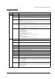
MR Series Technical Reference Manual Revision Table Rev. Page Description Rev. A All pages Newly authorized Rev. B Chapter 5 BIOS updated from 2.06 to 2.08 9-2 Added explanation and listing of "touch panel position adjust jig" in "Required Tools". Reason for change: The tool is now supplied for assembling the touch panel assembly. 9-18—20 Added new explanation for installation of the touch panel assembly.
Rev. Rev.D Page Description 9-24,27,28,37 Added the explanation for disassembly and assemblyof the parts below. -PCI card -Switch cable assembly 9-29 The method of disassembly and assembly the CD/FDD bracket is changed. The changed point. One screw and stopper is added to fix the CD/FDD bracket correctly. Reason for change; The part is changed to prevent the CD/FDD bracket from connection failure. B-11—15 Added parts list and block diagram for the model DM-M820-015.
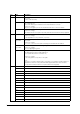
MR Series Technical Reference Manual Rev. Page Description Rev.F 4-73-77 5-1,15,19,20 5-30 Add the HDD Power Down Settings. 5-1,2,15,19 5-20,30 Add the BIOS Ver.2.13.00. 3-6 Add the RTC (Real Time Clock). v,vii 1-1,3,4,, 9,10 2-1,3,5,6 3-1,4,,6 8-3,14,15,18 8-23 9-25,30,31 9-51 -54 B-16 -24 Add the IM-800 with TM Printer Power Supply model. 1-1,11 B-2 -15 Add the DM-M820 High brightness model. 9-33,42 Add the notes. 9-50 Add the Speaker instdliation. B-16 -24 Add the COM cable, B. Rev.
Cautions ❏ No part of this document may be reproduced, stored in a retrieval system, or transmitted in any form or by any means, electronic, mechanical, photocopying, recording, or otherwise, without the prior written permission of Seiko Epson Corporation. ❏ The contents of this document are subject to change without notice. Please contact us for the latest information.
MR Series Technical Reference Manual Important Safety Information This section presents important information intended to ensure safe and effective use of this product. Read this section carefully, and store it in an accessible location. Key to Symbols The symbols in this manual are identified by their level of importance, as defined below. Read the following carefully before handling the product. WARNING: Warnings must be followed carefully to avoid serious bodily injury.
Do not charge the internal lithium battery or leave it in a hot place such as near a fire or on a heater because it could overheat and ignite. When you dispose of the internal lithium battery, insulate it by wrapping the terminals with tape. Mixing the battery with other metals or batteries may lead to fire, heat, or explosion. Be sure your power cable meets the relevant safety standards and includes a power system ground terminal (PE terminal).
MR Series Technical Reference Manual Be sure to set this product on a firm, stable, horizontal surface. The product may break or cause injury if it falls. Do not use the unit in locations subject to high humidity or dust levels. Excessive humidity and dust may cause equipment damage, fire, or shock. Do not use the unit in locations subject to liquids, since this product is not waterproof.
If you turn off the unit, wait at least 10 seconds before you turn it on again. Safety Precautions for the DM-M820 WARNING: Turn off the power switch immediately and unplug the DC plug if the DM-M820 or AC Adapter produces smoke, a strange odor, or unusual noise. Continued use may lead to fire or electric shock. Contact your dealer or an EPSON service center for advice. The DM-M820 contains a glass panel. If the DM-M820 is dropped or treated roughly, the glass may break.
MR Series Technical Reference Manual Safety Precautions for the OI-MR01 AC Adapter WARNING: Shut down your equipment immediately if it produces smoke, a strange odor, or unusual noise. Continued use may lead to fire or electric shock. Immediately unplug the equipment and contact your dealer or a SEIKO EPSON service center for advice. Never attempt to repair this product yourself. Improper repair work can be dangerous. Never disassemble or modify this product.
CAUTION: Be sure your power cable meets the relevant safety standards and includes a powersystem ground terminal (PE terminal). Be sure to use this product only with a DM-M820 LCD unit. Do not connect it to equipment from other manufacturers. Use this product only for its intended application. Improper usage may lead to equipment damage, fire, or shock. Be sure to set this unit on a firm, stable, horizontal surface. Product may break or cause injury if it falls.
MR Series Technical Reference Manual About this Manual Aim of the Manual This manual was created to provide all information necessary for system planning, design, installation, application, and service of the MR series for designers and developers of POS systems and for servicers of the products.
Contents Revision Table . . . . . . . . . . . . . . . . . . . . . . . . . . . . . . . . . . . . . . . . . . . . . . . . . . . . . . . . . . . . . . . . . . . . . . . . . . . . . . Important Safety Information . . . . . . . . . . . . . . . . . . . . . . . . . . . . . . . . . . . . . . . . . . . . . . . . . . . . . . . . . . . . . . . . . . Key to Symbols . . . . . . . . . . . . . . . . . . . . . . . . . . . . . . . . . . . . . . . . . . . . . . . . . . . . . . . . . . . . . . . . . . . . . . . . . .
MR Series Technical Reference Manual Chapter 3 Hardware Specifications Hardware Block Diagram for IM-800 . . . . . . . . . . . . . . . . . . . . . . . . . . . . . . . . . . . . . . . . . . . . . . . . . . . . . . . .3-1 DMA . . . . . . . . . . . . . . . . . . . . . . . . . . . . . . . . . . . . . . . . . . . . . . . . . . . . . . . . . . . . . . . . . . . . . . . . . . . . . . . . . . . . . . .3-2 System Interrupts . . . . . . . . . . . . . . . . . . . . . . . . . . . . . . . . . . . . . . . . . . . . . . .
Installation for Windows 98 Locally Procured Edition . . . . . . . . . . . . . . . . . . . . . . . . . . . . . . . . . . . . . . . . . . . . Installation Procedure . . . . . . . . . . . . . . . . . . . . . . . . . . . . . . . . . . . . . . . . . . . . . . . . . . . . . . . . . . . . . . . . . . . . Setup Procedure . . . . . . . . . . . . . . . . . . . . . . . . . . . . . . . . . . . . . . . . . . . . . . . . . . . . . . . . . . . . . . . . . . . . . . . . . Installing the Chipset Driver for Intel . . . . .
MR Series Technical Reference Manual Chapter 6 Operation of the IM-800 and the DM-M820 IM-800 Power . . . . . . . . . . . . . . . . . . . . . . . . . . . . . . . . . . . . . . . . . . . . . . . . . . . . . . . . . . . . . . . . . . . . . . . . . . . . . . . .6-1 Force Power Off . . . . . . . . . . . . . . . . . . . . . . . . . . . . . . . . . . . . . . . . . . . . . . . . . . . . . . . . . . . . . . . . . . . . . . . . . .6-1 LEDs for IM-800 . . . . . . . . . . . . . . . . . . . . . . . . . . . . . . . . .
Chapter 9 Disassembly and Assembly Disassembly and Assembly of the DM-M820 . . . . . . . . . . . . . . . . . . . . . . . . . . . . . . . . . . . . . . . . . . . . . . . . . . . . Determining which procedure to use . . . . . . . . . . . . . . . . . . . . . . . . . . . . . . . . . . . . . . . . . . . . . . . . . . . . . . . Precautions Before Assembly and Disassembly . . . . . . . . . . . . . . . . . . . . . . . . . . . . . . . . . . . . . . . . . . . . . . . . . . Conceptual Work Diagram for DM-M820 . . . .
MR Series Technical Reference Manual Appendix A Jumper Settings IM-800 Jumper Settings . . . . . . . . . . . . . . . . . . . . . . . . . . . . . . . . . . . . . . . . . . . . . . . . . . . . . . . . . . . . . . . . . . . . . . .A-1 2.5”HDD Jumper Settings . . . . . . . . . . . . . . . . . . . . . . . . . . . . . . . . . . . . . . . . . . . . . . . . . . . . . . . . . . . . . . . . . . . . .A-1 DM-M820 Jumper Settings . . . . . . . . . . . . . . . . . . . . . . . . . . . . . . . . . . . . . . . . . . . . . .
xviii Rev.
MR Series Technical Reference Manual Chapter 1 Features and Overview Features The MR is a modular-type POS terminal consisting of a base unit, which is the IM-800, and a display unit, which is the DM-M820. The IM-800 and the DM-M820 are also sold separately. IM-800 Features ❏ IBM® PC/AT® compatible ❏ Intel® Celeron™ (FC-PGA/FC-PGA2 package) can be used. Either a 733 MHz or a 1.2 GHz Celeron is factory installed.
❏ Power is supplied from the IM-800 or the OI-MR01 AC Adapter. The AC Adapter is used if the DM-M820 is bought by itself instead of with an IM-800. *1 Applies only to models with a stain-resistant Touch Panel. *2 Applies only to models with a Touch Panel. *3 Applies only to models with an MSR, which is sold only with the IM-800. Model Configurations The MR is composed of the IM-800 and the DM-M820. IM-800 CPU 733MHz, 1.2GHz HDD One 3.5" HDD, Two 2.
MR Series Technical Reference Manual Part Names for IM-800 Front view Ventilation opening USB ports CD/FDD cover Power switch Power HDD LED LED With CD/FDD cover open FDD LED CD-ROM drive(option) Rev.
Rear Cover Rear cover Rear view(Standard model) Mouse COM1 port Keyboard LPT port PCI slot COM3 port COM2 port Display port Line-out output DC 12V output (for DM-M820) Line-in Mic input input Ethernet port USB port AC voltage select switch AC Inlet COM4 port Rear view(24V model) DC 24V output (for TM printer) Mouse Keyboard PCI slot COM3 port COM2 port DC 12V output COM1 port LPT port 1-4 Features and Overview Display port Line-out output Ethernet port USB port Line-in Mic input i
MR Series Technical Reference Manual . Inside view(for the Standard model) Rear Side COM Port Circuit Board Assembly CPU PCI card DIMM Power Supply CD-ROM Drive HDD FDD Speaker (for the Speaker model) Inside view(for the 24V model) Front Side Rear Side COM Port Circuit Board Assembly DC 24V Board CPU PCI card DIMM Power Supply CD-ROM Drive HDD FDD Speaker (for the Speaker model) Rev.
Part Names for DM-M820 Model with MSR LCD / touch panel* Function control buttons Adjustment control Power switch Power-On LED Card Slot** MSR unit** LED for MSR** Model without MSR LCD / touch panel* Function control buttons Adjustment control Power switch Power-On LED 1-6 Features and Overview Rev.
MR Series Technical Reference Manual Rear view LCD stand Stand tab Cable A / Cable B / Cable C / Cable A (with a touch panel and an MSR) Display connector DC plug Serial port connector Rev.
Cable B (without a touch panel and an MSR) Display connector DC plug Cable C (with a touch panel, without an MSR) Serial port connector DC plug Display connecter . AC Adapter (OI-MR01) Power LED AC inlet DC plug * Applies only to models with a touch panel. ** Applies only to models with an MSR. 1-8 Features and Overview Rev.
MR Series Technical Reference Manual Specifications IM-800 Item CPU Memory Usable CPU types *1) Celeron 733 MHz or 1.2 GHz Socket 370-pin socket Main memory *2) 168-pin DIMM slots × 2 3.3V PC100 SDRAM / Maximum 512MB BIOS ROM 512KB Chipset Intel 810E2 chipset Video controller Built-in chipset IO controller Winbond W83627F (controls FDD, COM1/2, PS/2, and parallel interface) ITE IT8872F (controls COM3/4) Mass storage FDD One 3.5" floppy drive (1.44MB / 720KB) HDD One 3.5" HDD or Two 2.
Item Specifications Lithium battery Power supply The IM-800 is internally equipped with a Lithium non-rechargeable battery that supplies the backup voltage to the RTC and the RTC's builtin CMOS RAM when AC power is not supplied. The battery can be exchanged easily because the battery is connected through the socket.
MR Series Technical Reference Manual DM-M820 Item LCD Backlight Specification Size 12.1" Type Color TFT Resolution 800 × 600 dots Color 262,144 colors (Can emulate 16 M color display using the dithering function) Input signal 0.7V p-p, 75 ohm Scanning frequency Horizontal 24 to 69KHz, Vertical 50 to 85 Hz Dot clock frequency Max. 80MHz View angle Horizontal direction From the left 45º (typ.) to the right 45º (typ.) Vertical direction From the top 30º (typ.) to the bottom 10º (typ.
Item Specification Mass Approximately 5.0 kg {3.3 lb} Environmental conditions Condition: Operating range Storage range Temperature: 5 to 35°C {41 to 95°F} –10 to 50°C {14 to 122°F} Humidity (RH): 30 to 80% non-condensing 30 to 90% non-condensing The unit is not water resistant. Others Connection to the IM-800 through an exclusive DC cable. A button on the right side of the panel lets you adjust the backlight brightness. *1 Applies only to models with a touch panel.
MR Series Technical Reference Manual Dimensions IM-800 Dimensions: 315 (W) × 280 (D) × 88 (H) mm {12.4 × 11 × 3.5"} (excluding the rear cover) 365 280 315 (W) × 365 (D) × 88 (H) mm {12.4 × 14.4 × 3.5"} (including the rear cover) 88 (excluding the rubber feet) [Units : mm] 315 DM-M820 340 mm 250 mm 200 mm 305 mm Rev.
Underside of Base The dotted circle is the position and size of the hole in the table required if the DM-M820 is mounted on a table with the cable going down rather than out of the back of the LCD stand. 102 70 50 200 240 1-14 Features and Overview Rev.
MR Series Technical Reference Manual Chapter 2 Setup for the IM-800 and the DM-M820 Setting the AC Voltage for the IM-800 (For the Standard model) If you are using 100-127 V power, set the AC voltage switch to 115. If you are using 200-240 V power, set the AC voltage switch to 230. (The factory setting is 230.) If the setting is wrong, the system will be damaged and will not operate. Follow these steps: 1. Remove the warning sheet. 2. Set the AC voltage select switch.
If the IM-800 is placed horizontally with the rear cover installed, attach the rubber feet that are included or leave at least 1 cm {0.4"} of space from the bottom of the rear cover. 1cm or more Installing face Do not put anything that weighs more than 20 kg {44 lb} on the IM-800 when it is installed horizontally. Installing the DM-M820 Cable Arrangement When you plan your installation of the DM-M820, consider the cable that comes out of the base.
MR Series Technical Reference Manual Connecting the DM-M820 Be sure to unplug the power cable for the IM-800 or PC before you connect the cables for the DM-M820. Connectors on the IM-800 Serial port connectors DC plug Keyboard out Display connector Connector Cables for a DM-M820 with a Touch Panel and MSR ❏ DC plug Connects to the 12 VDC output of the IM-800. ❏ Display connector Connects to the display port of the IM-800. ❏ Serial port connector Connects to the touch panel COM1 or COM2 port.
Note: If you are using a DM-M820 with a touch panel, be sure to connect the serial port connector to COM1 or COM2. Do not use COM3 or COM4. Also if you are using a DM-M820 with a touch panel, do not install a mouse driver. Installing a mouse driver can prevent the touch panel from working. Connector Cables for a DM-M820 with No Touch Panel and No MSR ❏ DC plug ❏ Display connector Connect to the 12 VDC output of the IM-800 or AC adapter (OI-MR01). Connect to the display port of the IM-800 or PC.
MR Series Technical Reference Manual With the TM Printer Power Supply model PCI slot COM3 COM2 Mouse Keyboard Display COM1 LPT Line-out 12 VDC output for DM-M820 Line-in Mic input Ethernet AC Inlet COM4 USB Connecting Other Peripheral Devices to the IM-800 These are general instructions for the types of peripherals you may want to use. CAUTION: The12 VDC output is an exclusive power supply for the DM-M820. Do not use it for other peripheral devices.
Keyboard and Mouse To use a USB keyboard or mouse under MS-DOS or Windows NT, set USB keyboard support or USB mouse support in the Integral Peripheral section of the BIOS setup. Using a PS/2 mouse To use a PS/2 mouse, you must be sure that USB mouse support in the Integrated Peripheral section of the BIOS is set to Disabled (which is the factory setting). TM-Printer Use the dedicated power supply for the power supply of the TM-Printer.
MR Series Technical Reference Manual Attaching the Rear Cover The rear cover makes the back of the system look neat and protects the cables. 1. When you want the cables to exit the top of the rear cover, use pliers to break out the tabs. CAUTION: If burrs are left after the tabs are removed, they may cause cuts or scratches. Remove the burrs with a cutter or file. 2. Remove the screw from the lower right corner of the back of the unit. 3. Fit the tabs on the rear cover as shown below. tabs 4.
2-8 Setup for the IM-800 and the DM-M820 Rev.
MR Series Technical Reference Manual Chapter 3 Hardware Specifications Hardware Block Diagram for IM-800 Main Board I2C Bus Clock Generator ICS9248-9 6 66/100/133 MHz CPU Socket 370 S-DRAM PC100 DIMM 168 Pins X 2 810E GMCH (North Bridge) 82810E VRM 8.
DMA The IM-800 supports seven DMA channels. Channels 0, 1, 2, and 3 provide 8-bit data transfers; channels 4, 5, 6, and 7 provide 16-bit data transfers. The IM-800 uses channel 2 for the floppy disk drive controller and releases the other channels to the other devices. The following table lists the DMA channel allocation.
MR Series Technical Reference Manual Configuration of Circuit Boards Main Board CPU Fan Connector System Fan Connector Mouse Keyboard Power Switch Connector LED Connector ATX Connector BIOS Parallel COM1 CRT Line-Out COM2 Header Line-In Mic-In Primary IDE LAN USB x2 Secondary IDE DIMM Sockets FDD CPU Socket (370-pin) CD Audio Header Front USB Header JP15 JP10 Riser Card Slot Speaker Connector Speaker RTC Battery COMS CLEAR Jumper Rev.
Riser Board PCI Slot COM Board Slot DC12V Jack COM Board COM3 DC12V Input Connector JP2 JP1 COM4 Header DC24V Board DC24V Jack DC24V Input Connector PCI Slot CAUTION: Before using a PCI card, it is your responsibility to examine it carefully to confirm whether its specifications conform to the specifications described in this manual. To get the latest information about which PCI board can be used with this product, contact your EPSON dealer. The PCI slot is located on the riser board.
MR Series Technical Reference Manual The dimensions of installable PCI cards are shown below: 210 106.68 Maximum height of parts: 14.48 (maximum) Maximum height of parts on the soldering face: 2.67 (maximum) [Units:mm] Power Supply The IM-800 has an ATX power supply that switches the AC input by AC voltage select switch and does not have a switch to cut off the AC input.
24V model Input voltage/current: 100 - 127 VAC / 4A 200 - 240 VAC / 2A Input frequency: 50 ± 3 Hz / 60 ± 3 Hz Cooling fan: depending on Air intake type, fan rotation speed is automatically changed, the temperature in the power supply unit. MTBF: 200,000 hours Precautions: 2) When the protective circuit of the voltage power unit performs a shutdown, the protective circuit keeps working for a while. When this happens, unplug the power cable and wait for about 15 seconds; then plug the cable back in.
MR Series Technical Reference Manual Lithium Battery The IM-800 is internally equipped with a Lithium non-rechargeable battery, which supplies the backup voltage to the RTC and the RTC's built-in CMOS RAM (only when the AC power is not supplied). The battery can be exchanged easily because the battery is connected through the socket. Battery type: CR2032 Vendor: Sony, Maxell, Toshiba Battery life: Approximately 5 years When replacing batteries, be sure to use the types and manufacturers listed above.
3-8 Hardware Specifications Rev.
MR Series Technical Reference Manual Chapter 4 OS and Drivers Outline of This Chapter This chapter tells which Operating Sytems and Drivers can be used and how to install and uninstall them. CAUTION: Don’t write anything, such as an application to an HDD that is removed from the MR. The vibration and impact can cause trouble and the failure of the HDD. Operating Systems The following Operating Systems can be used for the IM-800.
Driver CD-ROM for the IM-800 The driver for installing a locally procured OS on the IM-800, the MSR utility for using the MSR of the DM-M820, and drivers for using the peripheral devices are on this CD-ROM. The CD-ROM directory is shown below.
MR Series Technical Reference Manual Touch Panel driver CD-ROM for the DM-M820 touch panel model The CD-ROM directory is shown below. Root |--- DOS |--- WIN--- European |--- Asian CDVER.TAG Touch Panel Driver for MS-DOS Touch Panel Driver for Windows98/NT/2000/XP for European Touch Panel Driver for Windows98/NT/2000/XP for Chinese T/ C,Korean Readme.txt files are in both the root directory and in subdirectories beneath the root directory. 1. The Readme.
Windows 2000 Pre-Installed Model The exclusive EPSON utility and drivers for using IM-800 are pre-installed in the HDD with the pre-installed Windows 2000 Professional. Installation Procedure Windows 2000 Installation When turning on the power supply, the installation starts. Enter the product key of the W2K label pasted on the product. You can set up the Network automatically or set it up later. When using the DM-M820 with Touch Panel, follow the steps as below.
MR Series Technical Reference Manual Pre-installed software ❏ Microsoft Windows 2000 Professional ❏ Microsoft Windows 2000 Service Pack 2 ❏ Multilingual User Interface (French, German, Italian, Spanish, Dutch, Portuguese) ❏ Intel Chipset software installation utility ❏ Intel Video driver ❏ Intel Network driver ❏ Analog Devices Sound driver ❏ ITE COM3/4 Driver ❏ EPSON DM-MS Series setup utility *1 Version of the Pre-installation HDD To confirm the version of the HDD, see the file HDVER.
Directory Configuration The root directory of the HDD is structured as follows.
MR Series Technical Reference Manual 3. The Regional Settings screen is displayed. Make sure the system locale, user locales and keyboard layout are set to United States, then click Next. 4. The Personalize Your Software screen is displayed. Input the Name and Organization, then click Next. 5. The Your Product Key screen is displayed. Input the product key entered on the cover of the First Step Guide in the COA (Certificate of Authenticity) package included with this product; then click Next. 6.
2. Pointer Device Properties is displayed. Click the Windows tab. 3. Click the Defaults button on the Double Click Settings group box. 4. Click OK. Installing the MSR Utility for Windows Install the MSR Utility by the following procedure. 1. Start C:\Backup\Msrcfg\ Win\Disk1\SETUP.EXE. 2. The Setup Wizard starts and the Welcome dialog box is displayed. Click Next. 3. The Choose Destination Location dialog box is displayed. Specify the directory where the program is to be installed and click Next.
MR Series Technical Reference Manual Recovering the OS Use the OS recovery media (CD-ROM) packed with the IM-800 to recover the OS. Follow the steps below to carry out OS recovery. 1. Turn power to the IM-800 off. Turn the main power switch off. Unplug the power cable. 2. If a CD-ROM drive is not already installed, attach a drive to the MR series. 3. Attach to the MR series the HDD unit you'd like to recover. 4.
13. The image data exchange dialog will appear. Insert the Windows 2000 CD-ROM 2 of 2 in the CD-ROM drive; then press the OK button. 14. When the prompt below is displayed on the screen, OS recovery work is complete. X:\>_ 15. Eject the “Windows 2000 CD-ROM” from the CD-ROM drive. 16. Reboot and start the BIOS setup utility. 17. Return the First Boot Device in the Advanced BIOS features setup menu to the “Floppy”. 18. On the main menu, select “Save & Exit Setup” and press the Enter key.
MR Series Technical Reference Manual Windows 98 Pre-Installed Model The HDD pre-installed with Windows 98 Second Edition is also pre-installed with the EPSON utility software and drivers dedicated to the IM-800. Languages are English, French, German, Spanish, and Italian. Installation Procedure Windows 98 Installation When turning on the power supply, the installation starts. Enter the product key of the W98 label pasted on the product. You can setup the Network automatically or setup it later.
❏ Intel Video driver ❏ Intel Network driver ❏ Analog Devices Sound driver ❏ ITE COM3/4 Driver ❏ EPSON DM-MS Series setup utility *1 Note: *1: These are not installed during the auto installation procedure. Version of the pre-installation HDD To confirm the version of the HDD, see HDVER.TAG in the start-up drive root. This file is textformatted and can be read using Notepad or a similar text editor. The contents of HDVER.TAG are as follows: [HD Information] MODEL=IM-800 OS= Windows98 LANG=English VER=1.**.
MR Series Technical Reference Manual Windows 98 Set-Up Procedure Windows 98 is set up by using the following procedure: 1. Connect the keyboard and mouse to the IM-800. 2. Turn on the PC to start Windows 98 SE. 3. The Enter Network Password dialog box is displayed. Input the password and click OK. 4. The Welcome screen is displayed. Input the necessary information and click Next. 5. The Windows End User license Agreement is displayed. Read it though and confirm your agreement to the terms.
5. The confirmation dialog box of the uninstalling is displayed. Select Yes. 6. Uninstalling is completed, and the dialog box is displayed. Click OK. Support Information Select the My Computer icon on the desktop, click the right mouse button and select Properties from the pull down menu. Click the Support Information button; the information on the contact is displayed. Recovering the OS Preparing recovery media ❏ Preparing a start-up disk 1. Start the command prompt. 2.
MR Series Technical Reference Manual 3. Write all data saved in step 2 onto a CD-R. 4. After saving the data, the directory under the C:\backup\recovery directory may be deleted. ❏ Backing up each driver Each directory under the C:\backup directory is the backup of each driver, which can be backed up through individual saving. Recovering method ❏ Editing the start-up disk Edit CONFIG.SYS and AUTOEXE.BAT created in “Preparing a Recovery Medium” to the device on which the image data has been saved.
Installation for Windows XP Professional Locally Procured Edition Installation Procedure If you install Windows XP Professional locally procured edition, follow the steps below. Windows XP Professional Installation Insert the Windows XP startup disk and CD-ROM; then turn on the IM-800 to perform the setup. Enter the product key of the COA package. You can set up the Network automatically or set it up later. Serial port Driver Installation Install the software from the Driver CD-ROM for the IM-800.
MR Series Technical Reference Manual 4. The [END-USER LICENSE AGREEMENT] screen is displayed. Read it through and confirm contents. If you agree with them, press the F8 key. 5. Select the partition to set up Windows, and press the Enter key. When an unformatted partition is selected, a confirmation screen is displayed. Execute the format according to the instructions on the screen. After that, copying of the file starts. 6. Reboot the system again according to the instructions on the screen. 7.
2. Select [Start Menu] and open the control panel. 3. Select [Printers and Other Hardware] in the control panel. 4. Select [System] in the [See Also]. 5. The System dialog is displayed. Select the [Hardware] tab. 6. Click Device Manager. 7. Select [Other Devices] - [PCI Serial Port] in the list, and click Properties. 8. The Properties dialog box is displayed. Click Reinstall Driver. 9. The [Welcome to the Hardware Update Wizard] dialog box is displayed.
MR Series Technical Reference Manual Installation for Windows 2000 Professional Locally Procured Edition Installation Procedure If you install Windows 2000 Professional locally procured edition, follow the steps below. Windows 2000 Professional Installation Insert the Windows 2000 startup disk and CD-ROM; then turn on the IM-800 to perform the setup. Enter the product key of the COA package. You can set up the Network automatically or set it up later.
Setup procedure Windows 2000 is set up by using the following procedure: 1. Connect the keyboard and mouse to the IM-800. 2. Insert the CD-ROM of Windows 2000 in the CD-ROM drive and boot up the system. 3. The Setup Wizard starts, and the Welcome dialog box is displayed. Select [Install a new copy of Windows 2000], and then click Next. 4. The License Agreement is displayed. Read it through and confirm your agreement to the terms. And then select [I accept the agreement] and click Next. 5.
MR Series Technical Reference Manual 3. The System Properties dialog box appears. Click the Hardware tab. 4. Click the Device Manager button. 5. The Device Manager dialog box appears. Select the keyboard as shown in the illustration below and click the Properties button in the tool bar. Or right click to show the short-cut menu; then select Properties. Rev.
6. The keyboard dialog box appears. Click the Power Management tab. Check the Allow this device to bring the computer out of standby box and click OK. Installing the Intel Chipset Diver This is installed by the exclusive installation program. 1. Insert the Driver CD-ROM for the IM-800 in the CD-ROM drive. Start Win2K\Chipset\SETUP.EXE. 2. The Setup Wizard starts and the Welcome screen is displayed. Click Next. 3. The License Agreement screen is displayed. Click Yes. 4. The Readme.
MR Series Technical Reference Manual 2. The dialog box to confirm copying the file is displayed. Click Yes. 3. The Setup Wizard starts, the License Agreement dialog box is displayed. Select [I accept the terms in the license agreement] and click Next. 4. The dialog box which specifies the place of the copy of the file is displayed. Input the place and click Next. The default setting is C:\Intel_32. 5. When copying of the file is completed, the Release note is displayed. 6.
7. The confirmation dialog box of the uninstalling is displayed. Select that the [Yes, I want to uninstall this device], and click Next. 8. Uninstalling is completed and the dialog box is displayed. Click Finish. Installing the Display Driver This is installed by the exclusive installation program. 1. Insert the Driver CD-ROM for the IM-800 in the CD-ROM drive. Start Win2K\Video\Win2K-XPE66.EXE. 2. The Release note is displayed. Click Next. 3.
MR Series Technical Reference Manual 8. Uninstalling is completed and the dialog box is displayed. Click Finish. Installing the Serial Port Driver Note COM1/COM2 can be used without installing the driver. If you use COM3/COM4, you need to install the driver. If the standby mode of the Operating System is selected, the current mode automatically changes to the standby mode even if the data is being output to COM ports. 1. Insert the Driver CD-ROM for the IM-800 in the CD-ROM drive. 2.
Installation for Windows NT Locally procured edition Note If you use Windows NT, you need to install Service Pack 6a. Installation Procedure If you install Windows NT Local procured edition, follow the steps below. Operating System Installation Inseert the CD-ROM for Windows NT and turn on the IM-800 to perform the setup. Enter the product key of the COA package. You can set up the Network automatically or set it up later.
MR Series Technical Reference Manual Setup procedure Windows NT is set up by using the following procedure: 1. Connect the keyboard and mouse to the PC. 2. Insert the CD-ROM of Windows NT in the CD-ROM drive and boot up the system. 3. The Welcome to Setup screen dialog box is displayed. Press the Enter key. 4. According to the instructions on the screen, input the necessary items and continue installing. 5. The Windows NT Licensing Agreement dialog box is displayed.
4. The dialog box which specifies the place of the copy of the file is displayed. Input the place and click Next. The default setting is C:\Intel_32. 5. When copying of the file is completed, the Release note is displayed. 6. Open the Control Panel, and select Network. A dialog box is displayed. Click Yes. 7. The Network Setup Wizard starts. Check the [Wired to the Network] check box, and click Next. 8. Click Select from list. 4-28 OS and Drivers Rev.
MR Series Technical Reference Manual 9. Click Have Disk. 10. The Insert Disk dialog box is displayed. Input the directory specified by step 4, and click OK. The default setting is C:\INTEL_32. 11. The Select OEM option dialog box is displayed. Confirm that [Intel(R) PRO Adapter] is selected, and click OK. 12. The Intel(R) PRO Adapter is added to the network adapter. Click Next. 13. Select the network protocol. Set it to your system. Then click Next. Rev.
14. Select the network service. Set it to your system. Then click Next. 15. The following dialog box is displayed. When Next is clicked, installation starts. 16. The dialog box that specifies the directory of the copy origin is displayed. Insert the CD-ROM of Windows NT in the CD-ROM drive and input D:\ (if the CD-ROM drive is the D drive) and click OK. 17. In accordance with the environment used, continue the installation according to the instruction on the screen. 18.
MR Series Technical Reference Manual Uninstalling the network driver Uninstalling cannot be done. Installing Service Pack 6a This is installed by the exclusive installation program. 1. Insert the Service Pack 6a CD-ROM in the CD-ROM drive. Execute the “Nt4sp6\Sp6i386.exe” on the Service Pack 6a CD-ROM. 2. The Setup Wizard starts, the License Agreement dialog box is displayed. Select [Accept the license agreement] and click Install. 3. Installing is completed; then the dialog box is displayed.
4. A finished dialog box appears. Click OK. 5. The system reboots. Installing the Display Driver Before installing the display driver, be sure to install Service Pack 6a. This is installed by the exclusive installation program. 1. Set the Driver CD-ROM for the IM-800 to the CD-ROM drive. Start Winnt\Video\Winnt4E66.EXE. 2. The Release note is displayed. Click Next. 3. The Setup Wizard starts. The Welcome dialog box is displayed. Click Next. 4. The License Agreement dialog box is displayed. Click Yes. 5.
MR Series Technical Reference Manual 4. Click Add/Remove. 5. The Confirm File Deletion dialog box is displayed. Click Yes. 6. Uninstalling is completed and the dialog box is displayed. Click OK. 7. The reboot dialog box is displayed. Click OK. 8. Reboot the system. Installing the Serial Port Driver This is installed by the exclusive installation program. Note COM1/COM2 can be used without installing the driver. If you use COM3/COM4, you need to install the driver. 1.
Installation for Windows 98 Locally Procured Edition Installation Procedure If you install Windows 98 Locally procured edition, follow the steps below Windows 98 Installation Inseert the MS-DOS startup disk and CD-ROM for Windows 98 and turn on the IM-800 to perform the setup. Enter the product key of the COA package. You can set up the Network automatically or set it up later. Chipset Driver Installation Install using the Driver CD-ROM for the IM-800.
MR Series Technical Reference Manual Setup Procedure Windows 98 is set up by using the following procedure: 1. Connect the keyboard and mouse to the PC. 2. Insert the Startup disk of the MS-DOS to the FDD. Turn on the power supply to the system. 3. Insert the CD-ROM of Windows 98 in the CD-ROM drive and start the SETUP.EXE. The Setup Wizard starts. 4. The License Agreement is displayed. Read it through and confirm your agreement to the terms.
5. The Reboot dialog box is displayed. Confirm that the [Yes, I want to restart my computer now] is selected, and click Finish. 6. After the system is restarted, the Chipset drivers are installed. 7. After installation, according to the instruction on the screen, reboot the system. Uninstalling the chipset driver for Intel Uninstalling cannot be done. Ultra DMA Setting for the HDD You can set the HDD to the DMA mode by following the steps below. 1.
MR Series Technical Reference Manual 6. Check [DMA] in the [Option] group box. 7. The following dialog box appears. Click OK. 8. Click OK to close the GENERIC IDE DISK TYPE47 Properties dialog box. 9. Click Close to close the System Properties dialog box. 10. The following dialog box appears. Click Yes to restart the system. Installing the Network Driver This is installed by the exclusive installation program. 1. Insert the Driver CD-ROM for the IM-800 in the CD-ROM drive. Start Win98\Network\100PDISK.
4. The dialog box that specifies the location of the file is displayed. Input the place and click Next. The default setting is C:\Intel_32. 5. When copy of the file is completed, the Release note is displayed. 6. Select [Start Menu] - [Settings] and open the Control Panel. 7. Select [System] in the control panel. 8. The System dialog box is displayed. Click [Device Manager]. 9. Select [Other Device] - [PCI Ethernet Controller] in the list, and click Properties. 10. The Properties dialog box is displayed.
MR Series Technical Reference Manual Installing the Display Driver This is installed by the exclusive installation program. 1. Insert the Driver CD-ROM for the IM-800 in the CD-ROM drive and start \Win98\Video\Win9Xe66.EXE. 2. The Readme.txt dialog box is displayed. Click Next. 3. The Setup Wizard starts and the Welcome screen is displayed. Click Next. 4. The License Agreement dialog box is displayed. Click Yes. 5. Installing is completed and the Reboot dialog box is displayed.
6. The reboot dialog box is displayed. Confirm that [Yes, I want to restart my computer now] is selected, and click Finish. Installing the Serial Port Driver Note COM1/COM2 can be used without installing the driver. If you use COM3/COM4, you need to install the driver. If the standby mode of the Operating System is selected, the current mode automatically changes to the standby mode even if the data is being output to COM ports. 1. Insert the Driver CD-ROM for IM-800 in the CD-ROM Drive.
MR Series Technical Reference Manual Installation for MS-DOS Locally Procured Version Installation Procedure If you install MS-DOS Locally procured version, follow the steps below. Operating System Installation Insert the MS-DOS startup disk and turn on the IM-800 to perform the Setup. As for the installation procedure, refer to the MS-DOS manual. CD-ROM Driver Installation As for installing MS-DOS only, the CD-ROM drive for the IM-800 is not recognized.
Installing the CD-ROM Driver After installing the MS-DOS locally procured edition only, the CD-ROM drive of the IM-800 is not recognized. Therefore, use other PC to read the CD-ROM, and install the CD-ROM driver to the IM-800 after copying the CD-ROM driver to a floppy disk from the Driver CD-ROM for the IM-800. Note When using the CD-ROM driver, MSCDEX.EXE of MS-DOS is needed. Install the CD-ROM driver by the following procedure. 1.
MR Series Technical Reference Manual 2. Insert the Driver CD-ROM for the IM-800 in the CD-ROM drive. 3. Start \Dos62\Network\100PDISK.EXE. 4. The dialog box to confirm copying the file is displayed. Click Yes. 5. The Setup Wizard starts, and the License Agreement dialog box is displayed. Select [I accept the terms in the license agreement] and click Next. 6. The dialog box that specifies the place of the copy of the file is displayed. Input the place and click Next. The default setting is C:\Intel_32. 7.
7. Add the following description to the AUTOEXEC.BAT of MS-DOS with a text editor, and save it. The following is the example of the having the driver file in the C:\NWCLIENT\ directory. In case of having it in the other directory, describe as "CD [the directory name]". CD NWCLIENT LSL E100BODI IPXODI NETX 8. Turn off the IM-800 and connect it to the network. 9. Turn on the IM-800 and restart MS-DOS. Installing the Serial Port Driver Note COM1/COM2 can be used without installing this driver.
MR Series Technical Reference Manual Installation of Other Drivers Installing the Touch Panel Driver for Windows Note Be sure to set the touch panel driver to COM1 or COM2. COM3/COM4 cannot be used. This is installed by the exclusive installation program. 1. Insert the touch panel driver CD-ROM for DM-M820 in the CD-ROM drive. European: Start \Win\european\SETUP.EXE. Chinese T/C,korean : Start \Win\asian\SETUP.EXE. 2. Start the touch panel driver set up program. The Welcome screen is displayed. Click Next.
7. The Number of devices dialog box is displayed. Confirm the number 1 is specified. Click Next. 8. The Desktop Segment dialog box is displayed. Specify the Device Segment (the range to allocate the touch panel), enter the optional panel name. Click Next. Whole Desktop is usually the best choice. 4-46 OS and Drivers Rev.
MR Series Technical Reference Manual 9. The Select Controller dialog box is displayed. Select the [Gunze,AHL,Serial]. Click Next. 10. The Port dialog box is displayed. Specify the Serial Port. Check the Auto Detect box or enter the number of the COM port that you use. Click Next. Advanced is usually not needed. CAUTION: Be sure not to set the port to COM3/COM4. Rev.
11. The Ready to Install dialog box is displayed. Click Next. 12. Installation ends and the Install Successful dialog box is displayed. Click Finish. 13. After the installation, the dialog box is displayed. Click Yes. 14. After rebooting the system, the calibration of the touch panel is executed automatically. See “Touch Panel Calibration.” Uninstalling the touch panel driver for Windows Uninstall the touch panel driver by the following procedure. 1.
MR Series Technical Reference Manual 4. Click Add/Remove. 5. The Uninstall Universal Pointer Device Driver dialog box is displayed. Click Next. 6. The Uninstall Completed dialog box is displayed. Click Finish. 7. The dialog box to require rebooting the system is displayed. Click Yes and reboot the system. Installing the Touch Panel Driver for MS-DOS Note Be sure to set the touch panel driver to COM1 or COM2. COM3/COM4 cannot be used. This is installed by the exclusive installation program. 1.
TBMOUSE Command Line TBMOUSE mode Mode:1 If the screen is touched, the mouse cursor moves to the place that was touched and the left mouse button is pressed. After that, the finger can be slid across the screen with the left button held down. The mouse button is released if the finger is lifted from the screen. Mode:2 If the screen is touched, the mouse cursor moves to the place that was touched, but the left mouse button is not pressed.
MR Series Technical Reference Manual Uninstalling the MSR utility for Windows Uninstall the MSR Utility by the following procedure. 1. Select [Start Menu] - [Settings] and open the control panel. 2. Select [Add/Remove Hardware] in the control panel. 3. Select [DM-MS Series Configuration Utilities]. 4. Click Add/Remove. 5. The confirmation dialog box of the uninstalling is displayed. Select Yes. 6. Uninstalling is completed, and the dialog box is displayed. Click OK.
2. Select Programs - Gunze - U-TP - Calibrate in that order from the Start menu. 3. The calibration screen is displayed and an X mark is displayed in the top left corner of the screen. 4. Press the X mark’s intersection point on the screen. The X mark will then move to the top right of the screen. 5. Then press the X mark’s intersection point again. With the default setting, the X mark is displayed in 4 places: top left, bottom left, top right, bottom right. The calibration point is set from 2 to 25.
MR Series Technical Reference Manual Note In Windows NT/2000/XP, only an administrator can change the value. In Windows 2000 /XP, the tolerance needs to be made larger for each registered user account with this tool. Regular users can click [Default]. 1. Select Programs - Gunze - U-TP - Settings in that order from the Start menu. 2. Pointer Device Properties is displayed. Click the Windows tab. 3.
The touch panel settings tool can set detailed items related to touch panel operation. It consists of the following: ❏ Device Addition and the deletion of the device and the setting of the communication method. ❏ Hardware Setting the connect environment of the touch panel driver. ❏ Settings Setting the recognition condition at the touching time. ❏ Advanced Management of the touching position data and the setting of the beep.
MR Series Technical Reference Manual Touch Panel Driver setting property Start the display of the touch panel driver setting property by the following procedure. 1. Start Windows. 2. Select Programs - Gunze - U-TP - Settings in that order from the Start menu. 3. The Pointer Device Properties screen is displayed. If there is a Device Manager icon in the task tray, the Touch Panel Driver Setting Properties can be displayed by the following procedure. 1. Start Windows. Rev.
2. Click the icon on the task tray and select Settings from the Pull up menu. 3. The Pointer Device Properties screen is displayed. Devices The following screen is displayed if the Devices tab is clicked. ❏ [Add] The device name can be assigned to the touch panel system connected to the IM-800. There is no need to set it generally. ❏ [Remove] Delete the assigned touch panel system.
MR Series Technical Reference Manual Hardware The following screen is displayed if the Hardware tab is clicked. ❏ [Hardware settings for] Select the touch panel device name. Generally “Device 1" is selected. ❏ [Port] This sets the communication port. There is usually no need to change it. ❏ [Auto Detect] This detects the Port, the Address and the IRQ for the connected touch panel. There is usually no need to change it. ❏ [Address] This displays the address used. This item cannot be set here.
is overwritten by new data before it is processed sometimes occurs. When setting the FIFO, the overrun error can be avoided using the inner cache. This item is set to 8 generally, so there is no need to change it. ❏ [Check Port] This displays the time interval (the second) for checking the COM Port condition for connected the touch panel. This item cannot be set here. Settings The following screen is displayed if the Settings tab is clicked.
MR Series Technical Reference Manual ❏ [Averaging] This samples plural values of touch position data and averages them. The default setting is 0. If it is set higher, the program will ignore minute movements of the finger. Note: If the Averaging value is too high, the following of the cursor is not good and sometimes the cursor may fly to an unexpected location. ❏ [Low pass filter] This can filter and ignore the data containing jitters, noise and unusual data.
❏ [Sample rate] Set the rate to process the touch position data. The default setting is 100 (%). There is usually no need to change it. ❏ [Touchdown filter] When some first data of the touch position are unstable these data are ignored and the following data is processed. The default setting is 0. ❏ [Deglitch] The value of the touch position data is sometimes interfered with in an environment near equipment generating a lot of noise. Deglitch ignores data that varies more than the specified amount.
MR Series Technical Reference Manual Events The following screen is displayed if the Events tab is clicked. Set the layout of the operation at the touching and the mouse button operation as a click, a double click and so on. ❏ [Events for] Select the touch panel device name. Generally, the “Device 1" is selected. ❏ [Primary] Sets the operation when the left mouse button is chosen in the system tray or the mouse icon of the event selector.
❏ [Time/Time Left] If the screen is touched and the finger does not move within the specified time, a click is executed. The time is set at the Click time in the Settings tab. After the click, you can drag. A double click can be executed by keeping the finger in the same position after the click operation. ❏ [Time/Tap Left] If the screen is touched and the finger does not move within the specified time, a click is executed. The time is set at the Click time in the Settings tab.
MR Series Technical Reference Manual ❏ [None] When touching in the touch panel, the mouse cursor moves to the touched place but a click is not executed. General The following screen is displayed if the General tab is clicked. Set the display of the confirmation messages and the icons, beeps and so on. ❏ [Show icons in system tray] This sets whether to display the touch panel driver setting and the icon of the event selector at the system tray.
Button Modes The following screen is displayed for the Button Modes tab. Set the details of the operation of the button mode. ❏ [Edit mode] Select the button mode name to edit. It is possible to register new button modes. For the operation of each button mode, see the “Events” section. ❏ [Button (Left, Right)] Clicking the Left radio button selects the left click or the left double click operation to be edited.
MR Series Technical Reference Manual • Down 5: This sets the touch operation recognized as the 3rd click. (Down 5 becomes valid when it executed in the click time.) • Up 6: This sets the touch operation recognized as the 3rd click cancellation. The following are the choices for the trigger settings • None: Does not assign a touch operation. • Immediate: Executes immediately after a touch operation. • Touchdown: Executes when the panel is touched.
Windows The following screen is displayed if the Windows tab is clicked. Set the detailed items about the Double Click. ❏ [Time] This sets the time interval to recognize as a double click. The default is 900 ms. ❏ [Height] This sets the vertical space between the touch positions that will be recognized as a double click. The default is 64 pixels. ❏ [Width] This sets the horizontal space between the touch positions that will be recognized as a double click. The default is 64 pixels.
MR Series Technical Reference Manual Calibration The following screen is displayed when the Calibration tab is clicked. Set the detailed items about the calibration condition. ❏ [Calibration settings for] Select the touch panel device name to set. “Device 1" is usually selected. ❏ [Calibration modes] This names the calibration modes including user settings and loads the one selected. ❏ [Add] This saves a new set calibration mode. ❏ [Remove] This removes a saved calibration mode.
❏ [Transparent background] With this checkbox checked, the background in calibration execution becomes transparent and only the calibration point “X” is displayed. ❏ [Toolbars] This sets the area of the touch panel that is reserved for the toolbars. Status The following screen is displayed if the Status tab is clicked. This displays the communication mode of the touch panel device. About The following screen is displayed if the About tab is clicked.
MR Series Technical Reference Manual Test When you click the Test button, you can test the operation mode of the touch panel. Event Selector The Event Selector is the tool as switching between the Primary and the Secondary on the touch panel. The Primary and the Secondary are set in the Event tab of the Touch Panel Driver setting property. Starting the Event Selector Start the Event Selector by the following procedures. 1. Start Windows. 2.
3. The Event Selector starts and the dialog is displayed. When it has an icon in the task tray, the Event Selector can also be started with the following procedure: 1. Start Windows. 2. Click the icon in the task tray and select the Event Selector from the pull up menu. 3. The Event Selector starts and the dialog is displayed. Operation 1. Switching between the Primary and Secondary The Primary and Secondary can be switched by tapping the mouse icon in the Event Selector.
MR Series Technical Reference Manual Selecting the left button of the mouse icon selects Primary for the touch panel. Displayed in Dialog Displayed in Tasktray When Secondary is selected Selecting the right button of the mouse icon selects Secondary for the touch panel. Displayed on Dialog Displayed on Tasktray 2. Setting the details Detailed items can be set with the pull down menu of the Event Selector. When the right button on in the title bar is clicked, the pull down menu is displayed.
❏ [Text mode] This changes the picture of the mouse icon to the character display. Primary operation Secondary operation ❏ [Always on top] When this is selected the Event Selector icon is always displayed on top of other applications. ❏ [About Event Selector] This displays about the version information of the Event Selector. Touch Panel Driver for MS-DOS When the LCD panel is changed or the TTDOS is installed, calibrate the Touch Panel by using the calibration.
MR Series Technical Reference Manual 8. Then an “X” appears in another location on the screen. Touch the center of the “X.” 9. The message “Success” appears. Press the option key to return the main menu. 10. Input X to end the calibration program. 11. The message “Success” appears. The calibration program has ended. HDD Power Down Timer Setting When the time the HDD is not accessed exceeds the specified time, the HDD motor can be stopped. The method of setting depends on the OS.
3. Select the time in the [Settings for Home/Office Desk power scheme: Turn off hard disks] option. 4. Click [OK]. When there is no HDD access for the time set, the HDD Power Down Timer switches over to HDD Power Down and the motor of the HDD stops. Windows 2000 Professional 1. Select [Settings]-[Control Panel]-[Power Options] in the Start menu of Windows. 4-74 OS and Drivers Rev.
MR Series Technical Reference Manual 2. [Power Options Properties] is displayed. Click the [Power Schemes] tab. 3. Select the time in the [Settings for Home/Office Desk power scheme: Turn off hard disks] option. 4. Click [OK]. When there is no HDD access for the time set, the HDD Power Down Timer switches over to HDD Power Down and the motor of the HDD stops. Windows 98SE 1. Select [Settings]-[Control Panel]-[Power Management] in the Start menu of Windows. Rev.
2. [Power Management Properties] is displayed. Click the [Power Schemes] tab. 3. Select the time in the [Settings for Home/Office Desk power scheme: Turn off hard disks] option. 4. Click [OK]. When there is no HDD access for the time set, the HDD Power Down Timer switches over to HDD Power Down and the motor of the HDD stops. 4-76 OS and Drivers Rev.
MR Series Technical Reference Manual Windows NT Workstation 4.0 SP6a Controlling the HDD motor is done through the BIOS. For the details, see Chapter 5 “BIOS Function.” MS-DOS Ver.6.22 Controlling the HDD motor is done through the BIOS. For the details, see Chapter 5 “BIOS Function.” Shift to the HDD power ON When access to HDD occurs, the motor of HDD begins to start and the HDD becomes accessible. MSR Utility for Windows This driver is used to change the MSR settings.
When the program starts, the following screen appears. The following paragraphs define each item on the screen: ❏ Ignore MSR/Keyboard Command If this check box is checked, all commands to the keyboard firm are not accepted. Typically, this check box is checked for use with the external programmable keyboard. It has not been checked in the initial setting. Note: Be careful that if this check box is checked, this utility cannot be started unless the main body is turned off or reset.
MR Series Technical Reference Manual ❏ MSR Start/End Sentinels (Card Start, Card End, ISO/JIS1 Track 1 Start, ..., JIS2 Start, JIS2 End) The characters to be prefixed and affixed to the data during the MSR reading are specified. It is possible to specify this setting for each card and each track. Leave this field blank if no character is to be added.
While the setting is being transferred, the dialog box indicating the situation is displayed. While the key lock setting file is being transferred, the following is displayed: Writing Configuration #dd-d ... where “dd” is the key number, and “d” is the number of retry times up to six. While the setting file for this utility is being transferred, the following is displayed: Writing Configuration 0xhh-d ...
MR Series Technical Reference Manual Setting file An example of the setting file for this utility is shown below.
ValidTracks is specified to be 1, 2, 3, or J. When it is specified to be 1, track 1 can be read. When it is specified to be 2, track 2 can be read. When it is specified to be 3, track 3 can be read. When it is specified to be J, the JIS2 track can be read. More than one file may be specified by dividing them with. CodeDefinitionxx is described to make the character created while the MSR was being read original.
MR Series Technical Reference Manual Commands Run the utility by typing the command in the following format: PKMODE2.EXE[MSR] [US|JP|FR|GR|SP] [CMDOFF|CMDON] [TK0SS=string] [TK0ES=string] [TK1SS=string] [TK1ES=string] [TK2SS=string] [TK2ES=string] [TK3SS=string] [TK3ES=string] [TKJSS=string] [TKJES=string] [BEEP=ON|BEEP=OFF] [MSR=m...
TK3ES=string: TKJSS=string: TKJES=string: BEEP=ON: BEEP=OFF: MSR=m...: KEYTBL=pathname: /TRACE: /TRON: /TROFF: /VAL=xxh, yyh: /PARA[zzh]: /CODE[zzh]: /DATA: /KB128=ON: /KB128=OFF: Replaces the 3track end flag of the MSR with the string. The default is “?.” Replaces the JIS II type start flag of the MSR with the string. The default is “ “ (20th). Replaces the JIS II type end flag of the MSR with the string. The default is “%” (7th). Enables the buzzer sound when the magnetic card is read.
MR Series Technical Reference Manual Processing details The version is displayed as Firmware Version= V3.00. To obtain detailed version information, execute PKUPDT2.EXE. Note: This definition utility operates on MS-DOS. It does not operate in a DOS box (in Windows). Be sure to start MS-DOS before Executing. Because this MSR utility uses a keyboard interface in communication with the firmware, operation of an external keyboard and MSR read operations are strictly prohibited during execution.
As parameters execute correctly, the following messages are displayed: Status messages Parameter Message MSR1 MSR track1 MSR MSR default US US 101 keyboard JP JP 106 keyboard FR French keyboard GR German keyboard SP Spanish keyboard CMDOFF Command Function OFF CMDON Command Function ON TK0SS Card Start Sentinel = string TK0ES Card End Sentinel = string TR?SS Track? Start Sentinel = string TK?ES Track? End Sentinel = string TKJSS JIS2 Start Sentinel = string TKJES JIS2 End Sent
MR Series Technical Reference Manual Completion messages are shown below: Completion messages Message Description Firmware old version or invalid... Firmware version error, etc. Invalid parameter Parameter error Communication error Communication error Invalid pathname File error Automatic Definition Data Setting Utility For MS-DOS Outline This utility automatically sets the definition information of the POS keyboard of the IM-800.
Messages Messages Message Description EPSON POS Keyboard Auto Definition Utility Vx.xx.xx During startup Usage: PKLOAD data-file data-file: definition data file .K84 :84Key definition data .K28 :28Key definition data .KYL :KeyLock definition data .$$$ :PKUPLD saved data .FLD :PKUPLD2 saved data .PKL :PKMODE definition data Usage EPSON POS Keyboard Auto Definition Utility Vx.xx.xx Now transfer 28Key Definition data .........
MR Series Technical Reference Manual this file should be specified as [.PKL]. The format has the following sections and entries: File format Section Entry Parameter (underlined parameters are the default values) [General] Remarks Fixed value. Be sure to describe at the start. Version PKL100 Fixed value. Be sure to describe at the start. IgnoreCommands Selected from Off and On Be careful that if On is selected, the subsequent commands are not accepted.
The default setting (U.S. mode) is described as follows: [General] Version=PKL100 IgnoreCommands=Off [MSR] ValidTracks=1,2,3 Beep=On CodeType=US CardStart= CardEnd= Track1Start=% Track1End=? Track2Start=; Track2End=? Track3Start=+ Track3End=? Code Conversion Entry CodeDefinitionNN = Character Code, Key Number, Shift Mode CodeDefinitionNN : Specifies the character code to be defined. 'c' defines whether a character or numeral has been specified.
MR series Technical Reference Manual Chapter 5 BIOS Functions The IM-800 system ROM stores the following BIOS-related utilities. This chapter describes these utilities. ❏ BIOS setup ❏ Defaults and selectable options ❏ Power on self-test (POST) ❏ Device diagnostic utility HDD Power Down Timer Setting The HDD Power Down Timer settings are made through the OS in Windows XP/2000/98, but in Windows NT/95 and DOS, the settings are made through the BIOS, as detailed below.
Operating Procedure How to use setup To execute BIOS setup requires a PS/2-compatible keyboard. BIOS setup cannot be run from the touch panel alone. Start the BIOS setup utility using the following procedure: 1. Connect the keyboard to the keyboard/mouse connector. 2. Turn the power on to start up the MR series. 3. Press Del during the POST process, and the BIOS setup utility will start up.
MR series Technical Reference Manual Changing settings To choose an item, first move the cursor onto a desired field with the arrow keys. Next, select a value in the field with + (PageUp) or – (PageDown). Finally, select the Save & Exit Setup command in the main menu, which saves the currently displayed values of all the menus. BIOS Setup Main Menu The BIOS setup main menu contains the following items: Table A-1 BIOS setup main menu Rev.
Standard CMOS Features Menu In this menu, set the system clock and the calendar, set the disk drive parameters and the type of video subsystem, select among the error types that interrupt the power on self-test (POST), and so on. Table A-2 Standard CMOS Features menu Items Description Date Sets the date. (BIOS automatically determines the day of the week.) Press ← or → to move to the desired field (date, month, year).
MR series Technical Reference Manual Table A-2 Standard CMOS Features menu (continued) Items Drive A Rev. I Description Head This item indicates the number of heads for the connection device. The following differences occur, depending on the device detection method used. Auto: The value obtained by the device is displayed. Manual: The user can set the value within a range of 0-255 only when the access method is set as “CHS”.
Table A-2 Standard CMOS Features menu (continued) Items Description Video This setting pertains to the type of video adapter being used. Always use the “EGA/VGA” setting. Since this setting automatically selects the type of video adapter during startup (POST startup phase) and will thus change to “EGA/ VGA”. Halt On Sets the system stop conditions for startup (POST). The definitions for each of the settings are as follows. All Errors:Use this setting to stop the system when an error occurs.
MR series Technical Reference Manual Advanced BIOS Features Menu In this menu, set the basic BIOS settings, such as cache, boot-up sequence, and memory shadowing. Table A-3 Advanced BIOS Features menu Items Description Virus Warning This is the setting for the data write enable/ disable to the boot sector and partition table. For the default setting, Fail-Safe is “Enabled” and Optimized is “Disabled”. Enabled:This is the setting used to disable the write function.
Table A-3 Advanced BIOS Features menu (continued) Items Description Boot Other Device Even if a device search is performed in the order of First/Second/Third Boot Devices, and a device that is capable of performing the startup is not found, this setting can be used to execute/not execute the Boot Other Device function. The default setting is set as “Enabled”. Change the setting so that it is compatible with the system configuration.
MR series Technical Reference Manual Table A-3 Advanced BIOS Features menu (continued) Items Description Security Option Sets the password entry timing. The default setting is “Setup”. The password is set in Main Menu: Set Supervisor Password and Main Menu: Set User Password.If a password is not set in these items, this setting will have no significance.
Advanced Chipset Features Menu In this menu, set the items that rely on the chipset on the main board, such as the memory, the bus timing, and the system temperature setting. Since these settings are executed via Load Optimized Defaults, they are the optimum settings for the system and generally do not need to be changed. Be aware that because these settings pertain to the control timing, the apparatus may fail to start up if an incompatible setting is executed.
MR series Technical Reference Manual Integrated Peripherals Menu This menu sets the items related to I/O ports such as the IDE controller, the transfer mode, the serial ports, and the parallel port. Table A-7 Integrated Peripherals menu Items Description On-Chip Primary PCI IDE This setting is to enable/disable the IDE controller housed in the chip set (ICH2). All of the default settings are set as "Enabled". Always use the default "Enabled" setting.
Table A-7 Integrated Peripherals menu (continued) Items Description Init Display First This setting sets the priority level for the video adapter. The default setting is "Onboard". Since the IM-800 uses the video controller housed in the chip set (GMCH) as the priority level, use the default setting. Onboard: Choose this to give priority to the video controller built in the chip set (GMCH). PCI Slot: Choose this to give priority to the video adapter mounted in the PCI slot.
MR series Technical Reference Manual Table A-7 Integrated Peripherals menu (continued) Items Description Onboard Parallel Port This setting enables/disables the parallel controller (combination of the I/O address and IRQ resource for the parallel port) inside the S-I/O (W83627). The default setting is "278/IRQ7". There are 3 options, the "Disabled" setting, "378/IRQ7" setting and the "278/IRQ5" setting.
Table A-5 POWER MANAGEMENT SETUP menu (continued) Items Description Suspend Mode Select the time it takes for the system to enter Suspend Mode by BIOS from option settings. The default setting is Disabled. Be careful not to set the time value too small as the system may frequently switch between FullOn Mode and Suspend Mode. Setting for OS DOS: Because DOS does not have a suspend timer, use this setting to set the time to enter the Suspend mode.
MR series Technical Reference Manual Table A-5 POWER MANAGEMENT SETUP menu (continued) Items Description Resume by Alarm Use this setting to turn on the power with the alarm (date and time). Set Resume by Alarm to the desired setting to enable or disable this function. Enabled: Choose this to enable the alarm function.By selecting this, Date (of Month) Alarm and Time (hh:mm:ss) Alarm can also be set. Disabled: Choose this to disable the alarm function.This is the default setting.
Windows NT With Windows NT, the Restart dialog box is displayed when shutting down the operating system, and the system stops and waits for instructions. Therefore, either one of the following methods should be used. ❏ Set Soft-Off using PWR-BTTN to "Instant-Off" to turn the power supply off when the Power button is pressed. ❏ Change HAL to automatically turn the power supply off when the operating system is shut down.
MR series Technical Reference Manual ❏ Windows XP Since this operation system supports ACPI (PMOS), the settings in the operating system are valid and the settings in the BIOS are invalid. OS setting Full-On / Video-Off Standby Shutdown Shutdown Full-On Standby Standby Full-On Never No-Operation Full-On The power supply is turned off if the Power button is pressed for 4 seconds or more. Video Off Mode The BIOS does not have a Video Off function.
Because a delay with the system timer is generated if Windows NT enters the Suspend mode, the system is not allowed to enter the Suspend mode. Be aware that the suspend timer cannot be set by the BIOS. Also, the Delay 4 Sec. setting cannot be used because pressing the Power button when the Power Button setting is set to Delay 4 Sec. would cause the system to enter the Suspend mode. ❏ Windows 98/2000/XP Windows 98 and later operating systems have a standby function.
MR series Technical Reference Manual PNP/PCI Configurations Menu In this menu, set the IRQ and DMA assignment methods and other items. Do not change the default settings under normal conditions. Table A-6 PNP/PCI Configurations menu Rev. I Items Description PNP OS Installed Use this setting to select whether the operating system is compatible with Plug and Play (PnP). The default setting is Yes. Always use the default setting.
Defaults and Selectable Options The BIOS default, setup default, and selectable options of each item are as follows. Some items are not displayed and cannot be changed, depending on the settings of their master items. Standard CMOS Features 1) Date, time Item Options Notice Day of the week — Day of the week: Month Jan Feb Mar Apr May Jun Jul Aug Sep Oct Nov Dec Year, Month, Day: Selected from the options.
MR series Technical Reference Manual Item Options Notice IDE Primary Master None Auto Manual Set the detection method for the connection device. None: The connection detection is not executed. It is treated as disconnected software Auto: Auto detection is executed. The information held by the device is automatically applied. Manual: The information set by the user is applied. Access Mode CHS LBA Large Auto Set the access Method to the connected device.
Item Options Notice Landing Zone ----- This item indicates the head fixed track number for the connection device. The following differences will occur, depending on the device detection method used. Auto: The value obtained by the device is displayed. Manual: The user can set the value within a range of 0-65,535 only when the access method is set as “CHS”. (When connecting a device for which there is no particular value specified, the number “1” is specified as the maximum number of cylinders).
MR series Technical Reference Manual Advanced BIOS Features The basic items related to BIOS boot-up are as follows. Rev. I Item Options Fail-Safe default Optimized default Virus Warning Disabled Enabled Enabled Disabled External Cache Disabled Enabled Enabled Enabled CPU L2 Cache ECC Checking Disabled Enabled Enabled Enabled Processor Number Feature This is a function for specifying whether or not to acquire the serial number of a CPU model added from the Pentium III processor.
Item Options Fail-Safe default Optimized default Boot Up Floppy Seek Disabled Enabled Enabled Enabled Boot Up NumLock Status Off On Off Off Gate A20 Option Normal Fast Normal Fast Typematic Rate Setting Disabled Enabled Disabled Disabled Typematic Rate (Chars/Sec) *2 6 8 10 12 15 20 24 30 (6) (6) Typematic Delay (Msec) *2 250 500 750 1000 (250) (250) Security Option Setup System Setup Setup OS Select For DRAM > 64MB Non-OS2 OS2 Non-OS2 Non-OS2 HDD S.M.A.R.
MR series Technical Reference Manual Advanced Chipset Features The setup items related to the chipset are as follows.
Integrated Peripherals The setup items related to onboard peripherals are as follows.
MR series Technical Reference Manual Item Options Fail-Safe default Optimized default Onboard LAN Device Disabled Enabled Enabled Enabled IDE HDD Block Mode Disabled Enabled Disabled Enabled Onboard Lan Boot ROM Disabled Enabled Enabled Enabled Onboard FDC Controller Disabled Enabled Enabled Enabled Onboard Serial Port 1 3F8/IRQ4 2F8/IRQ3 3F8/IRQ4 3F8/IRQ4 Onboard Serial Port 2 3F8/IRQ4 2F8/IRQ3 2F8/IRQ3 2F8/IRQ3 Onboard Parallel Port Disabled 378/IRQ7 278/IRQ5 3BC/IRQ7 378/IRQ
POWER MANAGEMENT SETUP The setup items related to power management are as follows.
MR series Technical Reference Manual Item Options Fail-Safe default Optimized default Primary IDE 1 Disabled Enabled Disabled Disabled Secondary IDE 0 Disabled Enabled Disabled Disabled Secondary IDE 1 Disabled Enabled Disabled Disabled FDD, COM, LPT Port Disabled Enabled Enabled Enabled PCI PIRQ [A-D] Disabled Enabled Disabled Disabled Notes:If Resume by Alarm for the Date (of Month) Alarm and Time (hh:mm:ss) Alarm is set as “Enabled”, the user can specify the selection.
Notes: When Resources Controlled By is set to Manual, IRQ Resources, DMA Resources, and Memory Resources can be set by the user. When IRQ Resources is selected, resources PCI/ISA PnP and Legacy ISA can then be selected from the advanced settings screen. The IRQ resources that can be set are IRQ-3, 4, 5, 7, 9, 10, 11, 12, 14, and 15. When DMA Resources is selected, resources PCI/ISA PnP and Legacy ISA can be set from the advanced settings screen.
MR series Technical Reference Manual When the device diagnostic utility starts, the following screen appears. Use the cursor keys, [Enter] key and [ESC] key to navigate the menus and make selections. Cursor keys Use these keys to select and navigate the menus. Enter key Use this key to select an item. ESC key Use this key to cancel an operation.
Select Initialize from the menu bar to select the serial port connected to the TM printer and DMD. Exit Select Exit from the menu bar to exit the program. Device Status Display Screen image After the connection of the TM printer and DM-D is confirmed, the status of those devices is displayed. 5-32 BIOS Functions Rev.
MR series Technical Reference Manual TM Status The status displayed for TM Status is as shown below. The priority status items are displayed from high to low priority. If the device is not recognized, Disable or No communication is displayed. Displayed Status Status Hardware Error A hardware error occurred. Paper feeding The paper is feeding.
Drawer Password Select Drawer Password to display the password setting screen. Creating a password Changing a password Enter a case-sensitive password of 4 to 8 English alphanumeric characters. You will be asked to enter your password two times when creating a password and three times when changing a password. Creating a Password Enter a password in the Enter and Re-Enter fields.
MR series Technical Reference Manual M/B Information Select M/B Information from the pull-down menu to display the main board information. The displayed items are as follows. CPU This displays the CPU name.Example: Intel Celeron (TM) Speed This displays the CPU clock.Example: 733 Memory This displays the system's memory size.Example: 256 Video This displays the recognition status of the video controller in the chipset.
TM print test Select TM print test from the pull-down menu to conduct a print test of the TM printer. When the test is successfully completed, "TM print test: done" message appears. This test is performed regardless of the status of the modem signal. The status of the modem signal is displayed in COM Ports. DM display test Select DM display test from the pull-down menu to conduct a DM display test. When the test is successfully completed, "DM display test: done" message appears.
MR series Technical Reference Manual LPT1 loop-back Select LPT1 loop-back from the pull-down menu to conduct a signal wire test using the loopback connector of the parallel port. Please note that a test cannot be performed for the data wire. The test results are displayed in the following manner. LPT1 port is disabled The designated port is disabled.
5-38 BIOS Functions Rev.
MR Series Technical Reference Manual Chapter 6 Operation of the IM-800 and the DM-M820 IM-800 Power The IM-800 does not have a power switch to shut down the power. When AC power is supplied, even if the power is off, a minute electric current flows through the system. The power switch on the front turns the system power on or off. Force Power Off When you want to quit an application and the operating system forcibly, press the power switch for more than 4 seconds. Then unplug the power cable.
Opening and Closing of the CD/FDD Cover When opening the CD/FDD cover, push down the top of the CD/FDD cover as shown below. CD-ROM Emergency Ejection When the CD-ROM drive does not function properly, you can remove the CD-ROM by following the steps below: 1. Turn off the IM-800. 2. Insert a small, thin object, such as an extended paper clip, in the CD-ROM eject hole. 3. The disk tray pops out slightly; then pull it out gently.
MR Series Technical Reference Manual Indicators for DM-M820 LEDs There are two LEDs: the power LED for the LCD unit and the LED for the MSR. POWER LED MSR LED These LEDs have the following meaning: LED Color Meaning Power LED Green Power is on (during normal operation). Flashing green No video input signal detected. MSR* Off Power is off. Green Card reading is successful. Orange Card reading has failed. Off Waiting for card reading or power is off.
Hold both sides of the display and adjust the angle as shown below. How to Use a Touch Panel (for the Touch Panel Model) Be sure to use your finger or a polyacetal pen to input data to the touch panel. When the touch panel becomes dirty, wipe its surface lightly with a soft cloth or a cloth moistened with ethyl alcohol. CAUTION: Do not use the unit in locations subject to liquids, since this product is not water resistant.
MR Series Technical Reference Manual Chapter 7 Maintenance and Adjustment Cleaning the IM-800 Front Panel Ventilation Opening There are many small holes in the left of the front panel. Air enters here and goes out the ventilation openings on the rear side and right side. If these holes become clogged with dust, remove the dust with a small vacuum cleaner or other appropriate cleaning device.
Display Adjustment (SERIAL NO. *xxxx00xxxx*) To adjust the LCD display, use the Function and Adjustment control buttons on the right side of the LCD unit. When you press the top Function control button (↑) once, the On-Screen Display appears in the lower righthand corner of the screen. Function control buttons To select a function in the On-Screen Display, use the ↑ and ↓ Function control buttons, as shown in the table below. To adjust the selected function, press the + or – Adjustment control buttons.
MR Series Technical Reference Manual Number of times to press the Function buttons Setting items Function ↑ button ↓ button 3 Miscellaneous Menu 0 On-Screen Display H-POSITION To adjust the horizontal position of the On-Screen Display menu. 1 On-Screen Display V-POSITION To adjust the vertical position of the On-Screen Display menu. 2 MENU TIMER To select the On-Screen Display menu display time. 3 INFORMATION To display the information for the LCD.
Display Adjustment (SERIAL NO. *xxxx01xxxx*) To adjust the LCD display, use the On-Screen Display (OSD) menu. To adjust the OSD menu with the Function buttons, use the Adjustment buttons and Power button. FUNCTION button ADJUSTMENT button POWER button ❏ Displaying and closing the OSD menu To display the On-Screen Display menu, press the (↑) Function button once. To close the OSD menu, press the POWER button once.
MR Series Technical Reference Manual If you press the (↓) Function button once when the OSD menu is not displayed, the message shown on the right appears and the LCD is adjusted automatically. When the power of the DM-M820 is on and there is no video signal, the message shown on the right appears for a few seconds, and then the Power LED flashes. When signals that the DM-M820 cannot display are received, the message shown on the right appears.
Main menu Sub manu Function OSD Menu Setting OSD Display H-POSITION To adjust the horizontal position of the OSD menu. OSD V-POSITION To adjust the vertical position of the OSD menu. OSD MENU TIMER To select the OSD menu display time. CONTRAST To adjust the contrast level of the display. BRIGHTNESS To adjust the brightness level of the backlight. COLOR USER To select the color palette. ADJUST COLOR GREEN To adjust the density level of GREEN.
MR Series Technical Reference Manual Touch Panel Calibration Touch panel calibration adjusts settings to make the position the operator touches on the touch panel match the computer-recognized software position. Calibrate the touch panel in the following situations. ❏ When the LCD unit is replaced. ❏ When you want to fine-tune the touch points on the touch panel. ❏ When the touch point positions on the touch panel are not accurate.
Maintenance for AC Adapter ❏ To clean the unit, wipe with a dry or slightly moistened (and firmly wrung out) cloth. ❏ Never clean the unit while it is plugged into the wall outlet. ❏ Do not clean the unit with thinner, benzine, or alcohol. 7-8 Maintenance and Adjustment Rev.
MR Series Technical Reference Manual Chapter 8 Troubleshooting Flow of Troubleshooting Procedures Confirm and prepare in advance Check these standard items prior to beginning troubleshooting. (See page 8-2.) Breakdown of likely locations for each type of fault Check the detailed breakdown of causes of faults for individual units and components. (See page 8-2.) In addition to the flowchart shown above, you can use the Power On Self-Test (POST) messages to identify the causes of faults.
Preparations for Troubleshooting Before troubleshooting, check and, if necessary, correct the following points. ❏ When the IM-800 is used in your system, you can check for the causes of faults is in the IM-800 or peripherals by using the device diagnostics. ❏ Is the power voltage in the AC outlet normal? ❏ Are the peripherals turned on? (The EPSON customer display has its own power switch.
MR Series Technical Reference Manual MSR faults *1) Printer unit faults Serial port, parallel port, USB port, and keyboard / mouse port faults Power supply faults Faults that are difficult to diagnose System Unable to Start Power Supply Remains Off (Green Indicator Off (*)) and Display Screen is Blank ❏ Follow the procedures below. 1. Unplug the power cable. Leave it unplugged for about fifteen minutes; then plug it back in and try to start it again. 2.
3. Replace the display unit. 4. If the problem is solved in step 3, the display unit has failed. See the problems described under “LCD Display Faults“ on page 8-11 to troubleshoot the display itself. 5. Confirm whether replacing the main circuit board solves the problem. Display Indicator Comes On, POST Ends Normally, but System Does Not Boot from Hard Disk Drive ❏ Follow the procedures below. 1. Confirm that any floppy disk is pulled out of the FDD drive. 2.
MR Series Technical Reference Manual ❏ Check whether the system can now start from the replacement HDD. If the system starts, check the customer’s BIOS settings for any errors. If the system doesn’t start, the cause may be a faulty connection or a problem with an individual unit or the connector itself. Follow the procedures below. 1. Confirm whether replacing the HDD cable solves the problem. 2. Confirm whether replacing the power supply solves the problem. 3.
Power Management Faults Unable to Turn On System from USB Device Note that system power supply control using USB devices is not supported. Unable to Turn On System from Network ❏ Confirm that Wakeup by PCI card in the Power Management Setup is set to Enabled. • The measures described below assume there are no problems with customer network settings and the programs that control this function.
MR Series Technical Reference Manual Time Setting is Not Possible or Time Setting Disappears ❏ Follow the procedures below. 1. Confirm whether replacing the lithium battery on the main circuit board solves the problem. 2. Confirm whether replacing the main circuit board solves the problem. “CMOS Checksum Error” occurs frequently during the POST ❏ When the lithium battery is depleted, this error occurs.
Floppy Disk Drive Unit Faults Unable to Read from or Write to Floppy Disk ❏ Follow the procedures below. 1. Confirm whether using another floppy disk solves the problem. 2. Confirm that the setting of Drive A in Standard CMOS Features of BIOS is set to 1.44MB, 3.5 in. (Refer to Chapter 5.) ❏ Check whether the floppy drive is able to read or write. If the floppy disk drive is still unable to read or write, the cause may be a faulty connection or a problem with an individual unit or the connector itself.
MR Series Technical Reference Manual 2. Confirm whether replacing the HDD solves the problem. 3. Confirm whether replacing the main circuit board solves the problem. CD-ROM Faults Unable to Read Data from CD-ROM ❏ Follow the procedures below. 1. Check the surface of the disk for foreign matter, marks, and scratches. 2. Note that labels applied to the CD-ROM can cause data read errors. 3. If using DOS for the system, you need to use the specified driver.
• The CD-ROM drive tray can be opened by inserting the designated tool in the EJECT hole. 2. If using DOS for the system, use the specified driver. (To install the driver, refer to “Installing the CD-ROM driver“ in Chapter 4.) 3. Confirm whether replacing the CD-ROM solves the problem. Network Faults Unable to Connect to Network ❏ Follow the procedures below. 1. Check the network cable connections. 2.
MR Series Technical Reference Manual Speaker Faults Sound does not sound Adjust the sound in OS. First, confirm the setting of OS. ❏ Follow the procedures below. 1. In case of the Speaker model, exchange the speaker. 2. Confirm whether replacing the main circuit board solves the problem. LCD Display Faults LCD Display Screen Either Blank or Unstable ❏ Follow the procedures below. 1. Check the connection of the video connector. 2. Check the display setting of the display. (Refer to Chapter 7.) 3.
LCD Display Screen Too Dark, Too Bright or Cannot Be Adjusted ❏ Follow the procedures below. 1. Confirm whether adjusting the brightness level on the LCD solves the problem. 2. Confirm whether replacing the switch cable assembly solves the problem. 3. Confirm whether replacing the LCD circuit board solves the problem. 4. Confirm whether replacing the inverter board solves the problem. 5. Confirm whether replacing the LCD solves the problem.
MR Series Technical Reference Manual ❏ Check whether the touch panel can now function. If the touch panel can function, check the customer’s touch panel settings for any errors. If the touch panel cannot function, the cause may be a faulty connection or a problem with the individual unit or the connector itself. Follow the procedures below. 1. Confirm whether replacing the touch panel unit circuit board solves the problem. 2. Confirm whether replacing the touch panel unit solves the problem. 3.
Printer Unit Faults The power supply of the printer isn't turned on ❏ Follow the procedures below. 1. Check the power switch of the TM printer is turned on. 2. Check the power cable of the TM printer is connected with the TM printer. 3. Check the TM printer is connected to the power supply of the TM-800 or the outlet.When supplying the power from the IM-800 TM printer power supply built-in model, check the power cable connections. 4.
MR Series Technical Reference Manual ❏ If the printer unit is still not able to print, the cause may be a faulty connection or a problem with an individual unit or the connector itself. Follow the procedures below. 1. Confirm whether replacing the printer unit solves the problem. 2. Refer to the relevant technical manuals and service manuals for the printer in question. Deterioration in Print Quality ❏ Refer to the relevant technical manuals and service manuals for the printer in question.
5. For problems with the keyboard, confirm whether replacing the MSR assembly solves the problem. 6. For problems with the COM3 port, confirm whether replacing the COM cable solves the problem. 7. For problems with the COM3 or COM4 port, confirm whether replacing the COM port circuit board solves the problem. 8. For problems with the COM3 or COM4 port, confirm whether replacing the riser circuit board solves the problem. 9. Confirm whether replacing the main circuit board solves the problem.
MR Series Technical Reference Manual Possible Short in System ❏ Follow the procedures below. Note: In cases where the power supply short circuit protection shuts the power supply down, power will not come back on if the power is turned on immediately after being turned off. It is necessary to wait for a period of at least fifteen seconds before turning the power back on. Step Corrective Procedure 1 Remove all the devices listed below. • All peripheral devices connected to IM-800 interface board.
4. Confirm that the power consumption for the PCI slots, COM ports, keyboard/mouse port, and USB port conform to the specifications in the table below. Power supply Application Capacity + 5 VDC PCI slot, COM ports, keyboard/mouse, USB 2.0 A + 3.3 VDC PCI slot 1.0 A + 12 VDC PCI slot, COM ports 1.0 A – 12 VDC PCI slot 0.02 A +24 VDC TM printer 2A The individual ports possess the capacity limits in the table below.
MR Series Technical Reference Manual MSR Faults Unable to Read Cards ❏ Follow the procedures below. 1. Check whether an incompatible card type (track type) is used. 2. Check the reading face of the card. Note: Confirm whether the problem is resolved by removing the external connectors. The MSR and keyboard can not be used at the same time. 3. Confirm whether moving the display away from such noise sources as CRT displays and power supplies solves the problem. 4. Confirm the cable (Reference No.
POST Messages The Power On Self-Test (POST) checks the system configuration and hardware when power is turned on. If it detects any errors, it issues error messages and emits audible beeps. The following section explains the error messages. POST Messages During the POST, the BIOS either sounds a beep code or displays a message when it detects a correctable error. The following is a list of POST messages. An error message may be followed by a prompt to press F1 to continue or press DEL to enter setup.
MR Series Technical Reference Manual POST messages (Continued) Message Description ERROR INITIALIZING HARD DISK CONTROLLER This message is displayed when initialization of the hard disk drive controller fails. Check to see if there is an error in the hard disk drive (IDE) settings via the BIOS setup utility or if there is a malfunction in the hard disk or the connection. If no problem was found, replace the main board.
POST messages (Continued) Message Description MEMORY ADDRESS ERROR AT ... If an address error occurs during a memory test, that address is displayed. This error may be caused by a malfunction of the memory (DIMM) or the main board (including the memory controller). Try replacing these parts in turn to see if this solves the problem. If the memory has not been installed, this is indicated by an error beep at the early POST stage. MEMORY PARITY ERROR AT ...
MR Series Technical Reference Manual Procedures for Testing the Power Supply CAUTION: In the interests of safety be sure to conduct checks with the power supply disconnected from the main circuit board. Setup ❏ Tester ❏ Wire × 1 (for On signal input) ❏ Use the following procedures to test the power supply. Note: Protective circuits that protect against shorts, over current, and overheating are installed in the power supply.
5. Measure the voltage between each terminal on the 20-pin connector and the voltage of all drive connectors. If the voltage differs from that shown on the chart below, replace the power supply. 11 20 1 10 20-pin connector HDD End of Power Cable FDD and CD-ROM End of Power Cable Yellow(+12V) Black(GND) Black(+24V) White(GND) COM Port Circuit Board End of Power Cable Power supply voltage check Voltage system Measurement terminals Normal voltage +3.3 V system Pin 1 – pin 15 + 3.14 ~ + 3.
MR Series Technical Reference Manual 6. Disconnect the wire shorting pins 14 and 15 on the power supply’s 20-pin connector. Check that the power is off. If the voltages are not normal, replace the power supply. Power Supply Cable’s Voltage Check (*) Measurement terminals Signal name 1 +12 VDC Shell Frame GND top of the connector Shell Power supply connector This connector is used to connect the display (DM-M820) to an external power source.
8-26 Troubleshooting Rev.
MR Series Technical Reference Manual Chapter 9 Disassembly and Assembly This portion of the chapter provides instructions for disassembling the DM-M820. To reassemble the DM-M820, reverse the steps in this chapter, except where special instructions are given. Directions for each procedure in this chapter, such as up and down, right and left, or top and bottom, are as seen from the front of this product.
Disassembly and Assembly of the DM-M820 There are three models of the DM-M820. The DM-M820-013/023 is the model without a touch panel and without an MSR. The DM-M820-014/024 is the model with a touch panel and with an MSR. The DM-M820-015/025 is the model with a touch panel and without an MSR. The method of dissassembly of the inside components depends on when the unit was manufactured. Determining which procedure to use Check the label on the manufacture's plate at the base of the DM-M820. ❏ SERIAL NO.
MR Series Technical Reference Manual Precautions Before Assembly and Disassembly WARNING: Wait several minutes after turning off the power and disconnecting the AC before starting disassembly work. This precaution is necessary because as long as this product’s power supply is on, portions of the internal circuits are charged with extremely high voltages. CAUTION: Most of the components used in the manufacture of the circuit boards, LCD, and touch panel are static-sensitive devices.
Conceptual Work Diagram for DM-M820 Rear cover (103) Top cover of Base assembly (*) Front cover (102) MSR assembly (106) (*) LED circuit board (1045) Base assembly (117) Hinge Assemblies (118) Rear case attached with Base assembly Rear case (108) Rear panel (1042) Front case (109) LCD circuit board (111) (*) Touch panel circuit board (116) Inverter circuit board (112) DC Jack board (122) Front case (109) (*) Touch panel assembly (1056) or Touch panel unit (115) LCD (110) Switch circuit bo
MR Series Technical Reference Manual Disassembling the Base Assembly Base Assembly(117) Follow the steps below to disassemble the unit. 1. Disconnect the cables from the IM-800 connectors and the DC12V outlet. 2. Remove 1 screw (1049) securing the top cover of the base assembly. 3. Remove the top cover of the base assembly. screw (1049) top cover of the base assembly base assembly 4. Remove 8 screws securing the bottom plate. Remove the bottom plate.
5. Remove 4 screws (1048) securing the base assembly to the display hinges. Then, remove the base assembly. hinge assemblies screw (1048) screw(1048) 6. Pull the cables out from the base assembly as shown below. (The model with an MSR unit is used in the illustration below.) 1046 1047 1043 119 To install, reverse the removal procedure. 9-6 Disassembly and Assembly Rev.
MR Series Technical Reference Manual Hinge Assemblies Follow the steps below for disassembly. Note: The hinges on your display may not look exactly like those below. 1. Remove 4 screws (S01) securing the hinges to the rear case, and remove the display. screw (S01) screw (S01) 2. Remove 1 screw (1049) securing the top cover of the base assembly. Remove the cover. (See page 9-8) 3. Remove 4 screws (1048) securing the base assembly to the hinge assemblies. Remove the hinge assemblies. (See page 9-5.
Removing the Covers Rear Cover The instructions below describe the all models of the DM-M820. 1. Remove 6 screw caps and screws securing the rear cover. Then, remove the rear cover. screw (S01) screw (S01) rear cover screw (S02) screw (S02) Follow the steps below to assemble the unit. 1. Confirm the cables’s connection to the rear case. And when reattaching the covers, be careful not to catch the cables in the covers.
MR Series Technical Reference Manual Front Cover 1. Remove the rear cover. (See page 9-8.) 2. Remove 2 screw caps and screws (S09) securing the front cover. Then, remove the front cover. screw (S09) screw (S09) front cover To install, reverse the removal procedure. Rev.
Removing the Components (SERIAL NO. *xxxx00xxxx*) When removing the components for which the SERIAL NO is *xxxx01xxxx*, see page 9-27. MSR Assembly or LED Circuit Board 1. Remove the rear cover. (See page 9-8.) 2. Disconnect 1 screw (S01) and remove the front cable clamp. 3. Remove 3 screws (S01) securing the MSR assembly to the front cover. And disconnect the connector of the LED cable from the MSR assembly.
MR Series Technical Reference Manual Rear Case 1. Remove the rear cover. (See page 9-8.) 2. Remove the front cover. (See page 9-9.) 3. Remove the cables. DM-M820-014 /015 DM-M820-013 4. Remove the hinge assemblies from the rear case. (See page 9-10.) 5. Remove 2 screws (S04) and 2 hex screws (S06) securing the rear case. And remove the rear case. (The model with an MSR is used in the illustration below.
Removing the Front Case 1. Remove the rear case.(See page 9-11.) 2. Remove 2 screws (S15) securing the LCD assembly to the front case. After then remove 2 screws (S05) holding 2 ground wires (one on each side) and lift up the ground wires. (The model with a touch panel is used in the illustration below.
MR Series Technical Reference Manual Rear panel Follow the steps below for disassembly. 1. Remove the rear cover. (See page 9-8.) 2. Remove the front cover. (See page 9-9.) 3. Remove the rear case. (See page 9-11.) 4. Remove hex screws (S07). DM-M820-014/024/015/025 DM-M820-013/023 5. Remove 8 screws (S05) securing the rear panel to the LCD assembly. Then remove 2 screws (S05) holding 2 ground wires (one on each side) and lift up the ground wires. After that remove the rear panel.
Touch Panel Circuit Board Follow the steps below for disassembly. 1. Remove the rear cover. (See page 9-8.) 2. Remove the front cover. (See page 9-9.) 3. Remove the rear case. (See page 9-11.) 4. Remove the rear panel. (See page 9-13.) 5. Remove 4 screws (1051), and remove the touch panel circuit board. cables connected to the switch circuit board screw (1051) touch panel circuit board cables screws (1051) To install, reverse the removal procedure. 9-14 Disassembly and Assembly Rev.
MR Series Technical Reference Manual LCD Circuit Board Follow the steps below for disassembly for the model DM-M820-014/024 and DM-M820-015/ 025. 1. Remove the rear case. (See page 9-11.) 2. Remove 4 hex screws (S07) (two each for the two connectors). (See page 9-13.) 3. Remove 10 screws (S05) securing the rear panel to the LCD assembly. After that remove the rear panel. (See page 9-13.) 4. Disconnect the 4 cables shown below.
4. Disconnect the 3 cables from the LCD circuit board, and remove 2 screws (1050) holding 2 ground wires and lift up the ground wires. After that remove the 2 screws (1050) securing the plate. cable screw (1050) and ground wire cables connected to the switch circuit board cables cable: See Caution below screw (1050) and ground wire LCD circuit board screw (1050) screw (1050) CAUTION: Remove the cable on the right side very carefully because its connection is not strong. 5.
MR Series Technical Reference Manual Inverter Circuit Board Follow the steps below for disassembly for the model DM-M820-014 and DM-M820-015/025. 1. Remove the rear case. (See page 9-11.) 2. Remove 4 hex screws (S07) (two each for the two connectors). (See page 9-13.) 3. Remove 10 screws (S05) securing the rear panel to the LCD assembly. After that remove the rear panel. (See page 9-13.) 4. Disconnect 2 cables and remove 2 screws (1052). Remove the inverter circuit board.
Removing the Touch Panel Assembly Follow the steps below to disassemble the touch panel assembly (1056). 1. Remove the rear case. (See page 9-11.) 2. Remove the front case from the front panel unit. (See page 9-13.) 3. Remove the rear panel. (See page 9-13.) 4. Remove the LCD circuit board. (See page 9-15.) 5. Disconnect the touch panel cable from the cable for the circuit board, as shown below, by releasing the patch, and remove the touch panel cable.
MR Series Technical Reference Manual 6. Remove the screws (S05) securing the touch panel assembly to the front panel unit. Then remove the touch panel assembly by lifting up it. screws (S05) touch panel screws (S05) front panel unit Note: Lift up the touch panel assembly carefully. Otherwise, the double-coated electric-conductive tape attached to each plate and the LCD unit will come off incorrectly.
1. Remove the exfoliation paper attached with double-coated electric-conductive tape on the upper plate and lower plates. The illustration below shows the position of the exfoliation paper. exfoliation paper 2. Place the upper plate and the lower plate on the front panel unit, moving them to the center to align the position of the screw holes. front panel unit upper plate (120) lower plate (121) 3. Attach the plates to the front panel unit with the 4 screws (S05).
MR Series Technical Reference Manual 4. Remove the 6 pieces of exfoliation paper attached to the plates. upper plate (120) exfoliation paper lower plate (121) 5. Use the touch panel position adjust jig to adjust the position of the touch panel. touch panel position adjust jig 6. Attach the touch panel, being careful to align the corners. position of the characters touch panel (115) Note: Be sure to attach the touch panel with the character side up. 7.
CAUTION: To remove the touch panel position adjust jig, lift it up straight. Otherwise it may be damaged. Follow the steps below to attach the touch panel unit (115). Removing the Touch Panel Unit The first step is same to some steps (from 1 to 5) for removing the touch panel assembly(it is indicated in the explainment above). Note: In the product made at first, a spacer is attched on LCD. When replacing the touch panel unit, remove the spacer before attaching the touch panel unit. LCD spacer 6.
MR Series Technical Reference Manual Note: The front panel unit of the OLD model has only two screw holes. Therefore, when replacing it with new one, attach the new touch panel using two-sided tape instead of screws at two places (G ,H) When the front panel unit is a new frame, screw four places (E,F,G,H) E F When the front panel unit is an old frame, two places (G,H) cannot be screwed. Therefore, attach the touch panel unit to the rear panel using the two-sided tape at two places.
LCD Follow the steps below for disassembly for the model DM-M820-014/024 and DM-M820-015/ 025. Note: If you remove the LCD for the model DM-M820-013/023, follow the steps below except step 5. 1. Remove the rear case. (See page 9-11.) 2. Remove the front case. (See page 9-13.) 3. Remove the rear panel. (See page 9-13.) 4. Remove the LCD Circuit Board. (See page 9-15.) 5. Remove the touch panel unit or touch panel assembly. (See page 9-18 or page 9-22.) 6. Disconnect 1 cable from the inverter circuit board.
MR Series Technical Reference Manual 8. Remove the LCD while pulling the cable from the hole. hole hole To install, reverse the removal procedure. Switch Circuit Board Follow the steps below for disassembly for the model DM-M820-014/024 and DM-M820-015/ 025. Note: If you remove the LCD for the model DM-M820-013/023, follow the steps below except step 5. 1. Remove the rear case. (See page 9-11.) 2. Remove the front case. (See page 9-13.) 3. Remove the rear panel. (See page 9-13.) 4.
7. Remove 1 screw (1050) holding 1 ground wire and lift up the ground wire. After that remove 1 screw (1050) securing the switch circuit board. . screw (1050) switch circuit board screw (1050) and ground wire 8. Remove the switch circuit board while pulling the cable from the hole. hole To install, reverse the removal procedure. 9-26 Disassembly and Assembly Rev.
MR Series Technical Reference Manual Removing the Components (Later the SERIAL NO. *xxxx01xxxx*) If removing components with SERIAL NO *xxxx00xxxx*, see page 9-10. MSR Assembly or LED Circuit Board 1. Remove the rear cover. (See page 9-8.) 2. Disconnect 1 screw (S01) and remove the front cable clamp. 3. Remove 3 screws (S01) securing the MSR assembly to the front cover. And disconnect the connector of the LED cable from the MSR assembly.
Rear Case 1. Remove the rear cover. (See page 9-8.) 2. Remove the front cover. (See page 9-9.) 3. Remove the cables. 4. Remove the hinge assemblies from the rear case. (See page 9-10.) 5. Remove 2 screws (S04) and 2 hex screws (S06) securing the rear case. And remove the rear case. (The model with an MSR is used in the illustration below.) screw (S04) screw (S04) rear case plate attached to the rear case hex screw (S06) hex screw (S06) Note: You need to attach the plate to the rear case you ordered.
MR Series Technical Reference Manual Removing the Front Case 1. Remove the rear case.(See page 9-11.) 2. Remove 2 screws (S15) securing the LCD assembly to the front case. screw (S15) screw (S15) front panel unit holding LCD assembly front case 3. Remove the front case. To install, reverse the removal procedure. CAUTION: To avoid damage during reassembly, do not apply pressure to any circuit boards when you fasten them in place. Rev.
Rear panel Follow the steps below for disassembly. 1. Remove the rear cover. (See page 9-8.) 2. Remove the front cover. (See page 9-9.) 3. Remove the rear case. (See page 9-11.) 4. Remove 4 hex screws (S07). DM-M820-014/024/015/025 5. Remove 8 screws (S05) securing the rear panel to the LCD assembly. After that remove the rear panel. screws (S05) screws (S05) rear panel screw (S05) screws (S05) screws (S05) Note: The ground wires are not attached to the model without a touch panel.
Touch Panel Circuit Board MR Series Technical Reference Manual Follow the steps below for disassembly. 1. Remove the rear cover. (See page 9-8.) 2. Remove the front cover. (See page 9-9.) 3. Remove the rear case. (See page 9-11.) 4. Remove the rear panel. (See page 9-13.) 5. Remove 4 hex screws (S07) and remove the cable. touch panel circuit board(116) hex screw(S07) cable 6. Disconnect the 2 cables shown below. Remove 2 screws (1051), and remove the touch panel circuit board.
LCD Circuit Board Follow the steps below for disassembly. 1. Remove the rear cover. (See page 9-8.) 2. Remove the front cover. (See page 9-9.) 3. Remove the rear case. (See page 9-11.) 4. Remove the rear panel. (See page 9-13.) 5. Disconnect the 3 cables shown below. Remove 3 screws (1050). cable screw (1050) cable screw (1050) LCD circuit board (111) CAUTION: Remove the cable on the right side very carefully because its connection is not strong. 6. Remove the LCD circuit board.
MR Series Technical Reference Manual Inverter Circuit Board Follow the steps below for disassembly. 1. Remove the rear cover. (See page 9-8.) 2. Remove the front cover. (See page 9-9.) 3. Remove the rear case. (See page 9-11.) 4. Remove the rear panel. (See page 9-13.) 5. Disconnect the 5 cables shown below. Remove 3 screws (1052). screw (1052) Inverter circuit board (112) cable 6. cable Remove the Inverter circuit board. To install, reverse the removal procedure. Rev.
DC Jack Board Follow the steps below for disassembly. 1. Remove the rear cover. (See page 9-8.) 2. Remove the front cover. (See page 9-9.) 3. Remove the rear case. (See page 9-11.) 4. Remove the rear panel. (See page 9-13.) 5. Disconnect the 1 cable shown below. Remove 2 screws (1052). cable DC Jack board(122) screw (1052) 6. Remove the DC Jack board. To install, reverse the removal procedure. 9-34 Disassembly and Assembly Rev.
MR Series Technical Reference Manual Removing the Touch Panel Assembly Follow the steps below for disassembly. 1. Remove the rear cover. (See page 9-8.) 2. Remove the front cover. (See page 9-9.) 3. Remove the rear case. (See page 9-11.) 4. Remove the front case. (See page 9-12.) 5. Remove the rear panel. (See page 9-13.) 6. Release the lock of the connector at the cable connection part. Unplug the touch panel cable out from the cable of the touch panel board.
7. Remove four screws (S05) securing the touch panel set to the front panel unit while lifting the touch panel set. screw (S05) screw (S05) Touch panel set (1056) To install, reverse the removal procedure. Note: Attach the touch panel set (1056) after removing dust from the touch panel set and the surface of the LCD with an air sprayer. When reattaching the touch panel assembly, align the position of the holes in the touch panel assembly and the front panel unit. 9-36 Disassembly and Assembly Rev.
MR Series Technical Reference Manual LCD Follow the steps below for disassembly. 1. Remove the rear cover. (See page 9-8.) 2. Remove the front cover. (See page 9-9.) 3. Remove the rear case. (See page 9-11.) 4. Remove the front case. (See page 9-12.) 5. Remove the rear panel. (See page 9-13.) 6. Remove the touch panel assembly. (See page 9-14.) 7. Disconnect 2 cables from the inverter circuit board and disconnect 1 cable from the LCD circuit board.
8. Remove 4 screws (S16) and remove the LCD. screw (S16) LCD (110) screw (S16) Note: When attaching the LCD set, be careful not to insert the cable between the LCD and the frame. To install, reverse the removal procedure. 9-38 Disassembly and Assembly Rev.
MR Series Technical Reference Manual Switch Circuit Board Follow the steps below for disassembly for the model DM-M820-014/024 and DM-M820-015/ 025. Note: If you remove the LCD for the model DM-M820-013/023, follow the steps below except step 5. 1. Remove the rear case. (See page 9-11.) 2. Remove the front case. (See page 9-13.) 3. Remove the rear panel. (See page 9-13.) 4. Remove the LCD Circuit Board. (See page 9-15.) 5. Remove the touch panel. (See page 9-18.) 6. Remove the LCD. (See page 9-24.) 7.
Disassembly and Assembly of the IM-800 This portion of the chapter provides instructions for disassembling the IM-800. WARNING: Wait several minutes after turning off the power and disconnecting the AC before starting disassembly work. This precaution is necessary because as long as this product’s power supply is on, portions of the internal circuits are charged with extremely high voltages. CAUTION: While the power is on, some parts inside this product reach high temperatures.
MR Series Technical Reference Manual Conceptual Work Diagram for IM-800 IM-800 rear case (203) IM-800 upper case (1009) (*) CD/FDD bracket (1008) GASKET, B (226) (*) SPRING, A (227) CD-ROM (219) System fan (214) DIMM (204) Riser frame (1006) CD/FDD bracket (1008) HDD bracket (1007) FDD (211) 2.5"HDD (206) 3.
Removing the IM-800 Rear Case To remove the IM-800 rear case, follow these steps: 1. Remove 3 screws indicated by the arrows below. IM-800 rear case 2. Remove the IM-800 rear case. To install, reverse the removal procedure. Removing the Covers IM-800 Upper Case 1. Remove the two screws (S13) indicated below: screw (S13) 2. Push the IM-800 rear case toward the front of the unit and then lift it off as shown below. IM-800 upper case 9-42 Disassembly and Assembly Rev.
MR Series Technical Reference Manual 3. If it is necessary to remove the IM-800 front case assembly (usually it is not necessary to remove it), remove the 5 screws (S11) shown below and remove the IM-800 front case assembly. screw (S11) screw (S11) IM-800 front case assembly To install, reverse the removal procedure. Removing the Compornents Riser Frame 1. Remove the IM-800 upper case. (See page 9-42.) 2. Remove the screw (S13) indicated below.
COM Port Circuit Board Assembly 1. Remove the IM-800 upper case. (See page 9-42.) 2. Remove the riser frame. (See page 9-43.) 3. Remove the screw (S13) securing the COM port circuit board (indicated below) to remove the COM port circuit board. screw (S13) COM port circuit board PCI Card A PCI card can be inserted into the upper slot on the riser frame. 1. Remove the IM-800 upper case. (See page 9-42.) 2. Remove the riser frame. (See page 9-43.) 3.
MR Series Technical Reference Manual RAID Card A RAID card can be inserted into the upper slot on the riser frame. 1. Remove the IM-800 upper case. (See page 9-42.) 2. Remove the riser frame. (See page 9-43.) 3. Remove the HDD cable from the RAID card. HDD cable RAID card 4. Remove the screw (S13) securing the PCI board (indicated below) to remove the RAID card. RAID card screw (S13) When replacing the PCI card, remove the dummy plate, if it is installed.
Riser Circuit Board 1. Remove the IM-800 upper case. (See page 9-42.) 2. Remove the riser frame. (See page 9-43.) 3. Remove the screw (S13) securing the COM port circuit board (indicated below) to remove the COM port circuit board. screw (S13) COM port circuit board 4. Remove the two screws (S13) securing the riser circuit board indicated in the illustration below to remove the riser circuit board. screw (S13) riser circuit board To install, reverse the removal procedure. DC24V board 1.
MR Series Technical Reference Manual 3. Remove the DC24V board by the procedures of 1 - 3. 4. Remove the cable of the power supply unit. To install, reverse the removal procedure. Note: Install the Power supply connecter for the DC 24V board just level with the rear case surface. NG Rev.
SPRING, A 1. Remove the IM-800 upper case. (See page 9-42.) 2. Remove the SPRING ,A from the frame as the figure. SPRING, A DC24V board Install by the following procedure 1. Remove the double-sides tape under the frame. 2. Paste a new double-sides tape ,A under the frame. Frame Double-sides tape ,A 3. Insert the SPRING ,A 4. Pinch the flame and the SPRING ,A with fingers to bond with the double-side tape. 9-48 Disassembly and Assembly Rev.
MR Series Technical Reference Manual CD/FDD Bracket 1. Remove the IM-800 upper case. (See page 9-42.) 2. Remove the CD-ROM cable (A), the audio cable (B), and the CD-ROM power cable (C) indicated below. Then remove the screws (S13) from locations D, E and F, also indicated below. A BC stopper E D dabo F Note: When you install the CD/FDD bracket, be certain that the stopper attached to the frame securely and attached the screw to the locations D. (See the illustration above.) 3.
Note: The position of the power supply cable is different for 3.5”HDD or 2.5”HDD. 3.5”HDD Model Power supply 3.5"HDD CD-ROM FDD 2.5”HDD Model Power supply 2.5"HDD CD-ROM FDD 4. Remove the FDD cable from the FDD circuit board. FDD circuit board 9-50 Disassembly and Assembly Rev.
MR Series Technical Reference Manual CD-ROM 1. Remove the IM-800 upper case. (See page 9-42.) 2. Remove the CD/FDD bracket. (See page 9-49.) 3. Remove the four screws (1020) indicated in the below illustration. Note: Rest two screws (1020) is attached to the side of opposite plate. screw (1020) CD/FDD bracket 4. Remove the CD-ROM in the direction of the arrow. CD-ROM audio connector CD/FDD bracket Note: Be careful not to break the audio connector inside the CD/FDD bracket.
FDD 1. Remove the IM-800 upper case. (See page 9-42.) 2. Remove the CD/FDD bracket. (See page 9-49.) 3. Remove the CD-ROM from the CD/FDD bracket. (See page 9-51.) 4. Remove the two screws (S12) indicated in the below illustration. screw (S12) CD/FDD bracket 5. Remove the FFC cable from the FDD by releasing the patch. FFC cable patch 6. Remove the FDD in the direction of the arrow. To install, reverse the removal procedure. Note: When you replace the FDD, attach the FFC with the tape.
MR Series Technical Reference Manual HDD bracket 1. Remove the IM-800 upper case. (See page 9-42.) 2. Remove the riser frame. (See page 9-43.) 3. Remove the CD/FDD bracket. (See page 9-49.) 4. Remove the HDD power cable (P3) from the HDD. Note: The position of the power supply cable is different for 3.5”HDD or 2.5”HDD. 3.5”HDD Model Power supply 3.5"HDD CD-ROM FDD 2.5”HDD Model Power supply 2.5"HDD CD-ROM FDD 3.5”HDD HDD bracket HDD power cable (P3) 2.
6. Remove the HDD cable(216) from the Main circuit board. HDD cable 9-54 Disassembly and Assembly Rev.
MR Series Technical Reference Manual 3.5”HDD The IM-800 has 3.5”HDD type and 2.5”HDD type. 1. Remove the IM-800 upper case. (See page 9-42.) 2. Remove the riser frame. (See page 9-43.) 3. Remove the CD/FDD bracket. (See page 9-49.) 4. Remove the HDD bracket, HDD power cable and HDD cable. (See page 9-53.) 5. Remove the HDD assembly in the direction of the arrow. Note: When you install the HDD assembly, the 4 clips must be hooked completely. clips clips HDD assembly 6.
CAUTION: Be careful not to drop the HDD when you remove it from the HDD bracket. 7. Pull out the 3.5”HDD from the HDD bracket while lifting up the 3.5”HDD in the direction of the arrow. Then disconnect the HDD cable and remove the 3.5”HDD. 3.5”HDD HDD cable To install, reverse the removal procedure. CAUTION: Be careful not to injure yourself on the sharp edges of the metal parts of the IM-800. 9-56 Disassembly and Assembly Rev.
MR Series Technical Reference Manual 2.5”HDD The IM-800 has 3.5”HDD type and 2.5”HDD type. 1. Remove the IM-800 upper case. (See page 9-42.) 2. Remove the riser frame. (See page 9-43.) 3. Remove the CD/FDD bracket. (See page 9-49.) 4. Remove the HDD bracket, HDD power cable and HDD cable. (See page 9-53.) 5. Remove the HDD assembly in the direction of the arrow. Note: When you install the HDD assembly, the 4 clips must be hooked completely. clips clips HDD assembly 6.
CAUTION: Be careful not to drop the HDD when you remove it from the HDD bracket. Be careful not to pinch the HDD cable when screwing. 7. Pull out the 2.5”HDD from the HDD bracket while lifting up the 2.5”HDD in the direction of the arrow. Then disconnect the HDD cable and remove the 2.5”HDD. 2.5”HDD HDD cable CAUTION: Be careful not to injure yourself on the sharp edges of the metal parts of the IM-800. 8. Remove two screws securing the 2HDD circuit board and remove the 2HDD circuit board.
MR Series Technical Reference Manual 10. To remove the second 2.5”HDD remove the four screws shown in the figure below securing the HDD and remove the SHORTPLUG for the 2.5”HDD. 2.5”HDD SHORT PLUG When you install two 2.5”HDD, the master or slave can be installed on the top or bottom. When you install the 2.5”HDD, you need to set the HDD jumpers properly. When connecting two 2.5”HDDs, one is Master and the other is Slave. Set Master/Slave by the jumper of the HDD. As for the procedure, see "HDD".
DIMM 1. Remove the IM-800 upper case. (See page 9-42.) 2. Remove the CD/FDD bracket. (See page 9-49.) 3. Open the tabs securing the DIMM at each end, as shown below. Then lift the DIMM out of the socket. To install, reverse the removal procedure. 9-60 Disassembly and Assembly Rev.
MR Series Technical Reference Manual System Fan 1. Remove the IM-800 upper case. (See page 9-42.) 2. Remove the CD/FDD bracket. (See page 9-49.) 3. Disconnect the system fan cable from the connector indicated below. system fan cable 4. Remove the two screws (1015) securing the system fan to the frame. CAUTION: When you remove or install the system fan, be sure to press the top of the system fan as indicated by the arrow while you remove or insert the screws. Otherwise you may bend the frame.
Switch cable assembly (218) 1. Remove the IM-800 upper case. (See page 9-42.) 2. Remove the CD/FDD bracket. (See page 9-49.) 3. Disconnect switch cable assembly (218) from the connector indicated below. power switch cable 4. Disattach the hooks of the power switch from the frame back side. (The illustration below shows the front side of the frame.) power switch hooks Front side Back side Note: When you attach a power switch to the frame, be careful that it is not inside out.
MR Series Technical Reference Manual CPU Cooler and CPU Follow the steps below for removal. CAUTION: The CPU cooler on the CPU may be hot after you turn off the power. Wait until it cools before you remove it. Note: When you replace a CPU, you must replace the CPU cooler too because the silicone that attaches the cooler to the CPU will come off when you take the CPU cooler off of the CPU. When you replace a CPU cooler without replacing the CPU, confirm that the silicone comes completely off of the CPU.
CAUTION: Remove the clip very carefully to avoid damaging any main circuit board components. 6. After you have unhooked one side of the CPU cooler, you can easily remove the CPU cooler by tilting it toward the other side and lifting it off. 7. Lift the CPU release lever in the direction of the arrow in the illustration until it is upright, and then pull the CPU straight up.
MR Series Technical Reference Manual Speaker 1. Remove the IM-800 upper case. (See page 9-42.) 2. Remove the riser frame. (See page 9-43.) 3. Remove the CD/FDD bracket. (See page 9-49.) 4. Remove the HDD bracket. (See page 9-53.) 5. Remove the Power Supply. (See page 9-67.) 6. Pull out the cable connecting the speaker from the main board. Speaker cable 7. Remove two screws fixing the speaker. screw Note: There is the main board which cannot connect the speaker. The way of discerning is as follows.
Install the Speaker by the following procedure 1. Peel off the tape of the Speaker Spacer and paste it on the speaker. 2. Adjust the Speaker cable to the lack of the Speaker holder and put the Speaker holder on the speaker. 3. Attach the speaker with two screws. Attach screws in the position of the following figure. screw Note: Install the cable of the speaker to become an underside. Install the speaker so as not to touch the frame of the IM-800.
MR Series Technical Reference Manual Power Supply 1. Remove the IM-800 upper case. (See page 9-42.) 2. Remove the riser frame. (See page 9-43.) 3. Remove the CD/FDD bracket. (See page 9-49.) 4. Remove the HDD bracket. (See page 9-53.) 5. Remove the two screws (S13) securing the power supply. screw (S13) 6. Remove the power cables connected to the main circuit board. 7. Cut the cable tie and remove the DC24V cable from the DC24V board.
8. Remove the power supply from the lower frame by first moving it in the direction of arrow 1, then in the direction of arrow 2. 2 1 lower frame To install, reverse the removal procedure. Note: During reassembly confirm that the power supply is attached to the lower frame as shown in the illustration above. CAUTION: Also, when you place the cable of power supply, put it under the USB cable. Do not arrange the cable of the power supply near the end of the case.
MR Series Technical Reference Manual Main Circuit Board 1. Remove the IM-800 upper case. (See page 9-42.) 2. Remove the riser frame. (See page 9-43.) 3. Remove the CD/FDD bracket. (See page 9-49.) 4. Remove the HDD bracket. (See page 9-53.) 5. Remove the DIMM. (See page 9-60.) 6. Remove the CPU cooler and CPU. (See page 9-63.) 7. Remove the cables on the main circuit board. 8. Remove the 5 screws (S13) shown in the figure below and remove the main circuit board. screw (S13) screw (S13) screw (S13) Rev.
To install, reverse the removal procedure. Note: When you change the main circuit board, you can use both the CPU and the CPU cooler attached to the old board. You need not to replace the CPU or the CPU cooler. CAUTION: Also, when you place the cable of power supply, put it under the USB cable. Do not arrange the cable of the power supply near the end of the case. Otherwise, it may be damaged when you install the IM-800 upper case or the CD/FDD bracket.
MR Series Technical Reference Manual Appendix A Jumper Settings IM-800 Jumper Settings The jumper settings for the IM-800 are as follows: PCB Jumper Function Setting Main control board JP10 Clearing the CMOS RAM 1-2: Normal (default) 2-3: Clear the CMOS RAM *1 JP15 Setting the serial IRQ for the PCI slot 1-2: Does not connect the serial IRQ to PCI slot 2-3: Connects the serial IRQ to PCI slot (default) JP1 Setting pin 1 of the COM4 port 1-2: DCD signal (default) 3-4: +5V power supply 5-6: +12
DM-M820 Jumper Settings Jumper settings for the touch panel board Jumper Location Set 1 > Set 10 SET 1, 2, and 3 are shorted. The others are open. LED of DM-M820 T/P board When power is supplied, the red LED lights. During data communication the green LED blinks. A-2 Jumper Settings Rev.
MR Series Technical reference Manual Appendix B Parts Information Part Life The following table shows the life of IM-800 parts. Table B-1 IM-800 part life Ref.# Part name Life 215 CPU cooler Approximately 80,000 hours. 45°C - Power supply fan (*) Approximately 70.000 hours. 45°C 214 System fan Approximately 80.000 hours. 45°C (*) Power supply fan is not supplied for an after service parts. The following table shows the life of DM-M820 parts. Table B-2 DM-M820 part life Rev. I Ref.
Confidential Part List DM-M820-013/023/113/123 Table B-1 DM-M820-013/023 /113/123 Ref.
MR Series Technical reference Manual DM-M820-013/023/113/123 Case Block S09 101 108 102 101 S09 109 S04 101 S06 S04 101 S15 1053 1055 101 S06 1054 S15 1041 1055 1054 S05 S02 101 S01 S05 S02 101 S05 S05 S07 S05 S05 S01 103 S02 101 S01 101 S05 S05 1042 S05 S01 117 Rev.
Confidential DM-M820-013/023/113/123 Component Block S16 110 S16 S16 S16 1050 1050 1050 113 112 111 1050 1050 1052 Appendix B-4 Parts Information Rev.
MR Series Technical reference Manual DM-M820-013/023/113/123 Base Unit Block 1049 117 1048 1048 118 1046 1047 1043 119 Rev.
Confidential Parts list DM-M820-014/024/114/124 (SERIAL NO. *xxxx00xxxx*) Table B-2 DM-M820-014/024 /114/124 Ref.
MR Series Technical reference Manual Table B-2 DM-M820-014/024 /114/124 Rev. I Ref.
Confidential DM-M820-014/024/114/124 (SERIAL NO. *xxxx00xxxx*) Case Block 108 S09 101 S04 101 S09 101 109 102 S06 S04 101 1053 1055 S15 101 S06 1054 1045 1055 S03 1054 S15 106 1041 S10 1044 S01 S10 S05 S02 101 S01 S05 S02 101 S05 S05 S07 S05 S05 S01 103 S02 101 S01 101 S05 S05 1042 S07 S05 S01 117 Appendix B-8 Parts Information Rev.
MR Series Technical reference Manual DM-M820-014/024/114/124 (SERIAL NO. *xxxx00xxxx*) Component Block S15 S15 S05 S15 120 S05 S15 S05 115 1057 121 S16 S16 114 S05 110 110 S16 S16 S16 S16 114 S16 S16 1050 1050 1050 1050 1050 1050 113 113 112 112 111 111 1050 1050 1050 1050 1052 116 1051 Rev.
Confidential DM-M820-014/024/114/124 (SERIAL NO. *xxxx00xxxx*) Base unit Block 1049 117 1048 1048 118 1046 1047 1043 119 Appendix B-10 Parts Information Rev.
MR Series Technical reference Manual Parts list DM-M820-014/024/114/124 (Later the SERIAL NO. *xxxx01xxxx*) Table B-3 DM-M820-014/024 /114/124 Rev. I Ref.
Confidential Table B-3 DM-M820-014/024 /114/124 Ref. # Name for technical reference manual Name for spare parts price list Part supply Unit 1049 Screw, M - No 1 1050 Screw, N - No 6 1051 Screw, O - No 4 1052 Screw, P - No 2 1053 Screw, Q - No 4 1054 Scrwe, R - No 2 1055 Screw, S - No 2 1056 Screw, T - No 2 Appendix B-12 Parts Information Rev.
MR Series Technical reference Manual DM-M820-014/024/114/124 (Later the SERIAL NO. *xxxx01xxxx*) Case Block 108 S09 101 S04 101 S09 101 109 102 S06 S04 101 1053 1055 S15 101 S06 1054 1045 1055 S03 1054 S15 106 1041 S10 1044 S01 S10 S05 S02 101 S01 S05 S02 101 S05 S05 S07 S05 S05 S01 103 S02 101 S01 101 S05 S05 1042 S07 S05 S01 117 Rev.
Confidential DM-M820-014/024/114/124 (Later the SERIAL NO. *xxxx01xxxx*) Component Block S15 S15 S15 S15 115 S16 110 S16 S16 S16 1050 1050 113 116 111 1050 112 1051 1050 S07 S07 122 1052 1054 Appendix B-14 Parts Information Rev.
MR Series Technical reference Manual DM-M820-014/024/114/124 (Later the SERIAL NO. *xxxx01xxxx*) Base unit Block 1049 117 1048 1048 118 1046 1047 1043 119 Rev.
Confidential Parts list DM-M820-015/025/115/125 (SERIAL NO. *xxxx00xxxx*) Table B-4 DM-M820-015/025/115/125 Ref.
MR Series Technical reference Manual Table B-4 DM-M820-015/025/115/125 Rev. I Ref.
Confidential DM-M820-015/025/115/125 (SERIAL NO. *xxxx00xxxx*) Case Block 108 S09 101 S04 101 102 101 S09 109 S06 S04 101 S15 1053 1055 101 S06 1054 S15 1055 1041 1054 S05 S02 101 S01 S05 S02 101 S05 S05 S07 S05 S05 S01 103 S02 101 S01 101 S05 S05 1042 S07 S05 S01 117 Appendix B-18 Parts Information Rev.
MR Series Technical reference Manual DM-M820-015/025/115/125 (SERIAL NO. *xxxx00xxxx*) Component Block S15 S15 S05 S15 120 S05 S15 S05 115 1057 121 S16 S16 114 S05 110 110 S16 S16 S16 S16 114 S16 S16 1050 1050 1050 1050 1050 1050 113 113 112 112 111 111 1050 1050 1050 1050 1052 116 1051 Rev.
Confidential DM-M820-015/025/115/125 (SERIAL NO. *xxxx00xxxx*) Base unit Block 1049 117 1048 1048 118 1046 1047 1043 119 Appendix B-20 Parts Information Rev.
MR Series Technical reference Manual Parts list DM-M820-015/025/115/125 (Later the SERIAL NO. *xxxx01xxxx*) Table B-5 DM-M820-015/025 /115/125 Rev. I Ref.
Confidential Table B-5 DM-M820-015/025 /115/125 Ref. # Name for technical reference manual Name for spare parts price list Part supply Unit 1053 Screw, Q - No 4 1054 Scrwe, R - No 2 1055 Screw, S - No 2 1056 Screw, T - No 2 Appendix B-22 Parts Information Rev.
MR Series Technical reference Manual DM-M820-015/025/115/125 (Later the SERIAL NO. *xxxx01xxxx*) Case Block 108 S09 101 S04 101 102 101 S09 109 S06 S04 101 S15 1053 1055 101 S06 1054 S15 1055 1041 1054 S05 S02 101 S01 S05 S02 101 S05 S05 S07 S05 S05 S01 103 S02 101 S01 101 S05 S05 1042 S07 S05 S01 117 Rev.
Confidential DM-M820-015/025/115/125 (Later the SERIAL NO. *xxxx01xxxx*) Component Block S15 S15 S15 S15 115 S16 110 S16 S16 S16 1050 1050 113 116 111 1050 112 1051 1050 S07 S07 122 1052 1054 Appendix B-24 Parts Information Rev.
MR Series Technical reference Manual DM-M820-015/025/115/125 (Later the SERIAL NO. *xxxx01xxxx*) Base unit Block 1049 117 1048 1048 118 1046 1047 1043 119 Rev.
Confidential Parts list (IM-800 for 3.5”HDD Model) Table B-6 IM-800 for 3.5”HDD Model Ref. # Name for technical reference manual Name for spare parts price list Part supply Unit 201 Label LABEL,EPSON LOGOTYPE,ECW4010 Yes 1 202 IM-800 front case assembly CASE,FRONT,ASS'Y Yes 1 203 IM-800 rear case CASE,REAR Yes 1 204 DIMM DIMM Yes 1 205 CPU CPU, Celeron Yes 1 206 3.5”HDD 3.
MR Series Technical reference Manual Table B-6 IM-800 for 3.5”HDD Model Rev. I Ref.
Confidential IM-800 for 3.
MR Series Technical reference Manual Parts list (IM-800 24V model) Table B-7 IM-800 3.5”HDD with TM Printer Power Supply and Speaker Model Rev. I Ref. # Name for technical reference manual Name for spare parts price list Part supply Unit 201 Label LABEL,EPSON LOGOTYPE,ECW4010 Yes 1 202 IM-800 front case assembly CASE,FRONT,ASS'Y Yes 1 203 IM-800 rear case CASE,REAR Yes 1 204 DIMM DIMM Yes 1 205 CPU CPU, Celeron Yes 1 206 3.5”HDD 3.
Confidential Table B-7 IM-800 3.5”HDD with TM Printer Power Supply and Speaker Model Ref.
MR Series Technical reference Manual IM-800 24V for 3.
Confidential Parts list (IM-800 for 2.5”HDD Model and Speaker Model) Table B-8 IM-800 for 2.5”HDD Model and Speaker Model Ref. # Name for technical reference manual Name for spare parts price list Part supply Unit 201 Label LABEL,EPSON LOGOTYPE,ECW4010 Yes 1 202 IM-800 front case assembly CASE,FRONT,ASS'Y Yes 1 203 IM-800 rear case CASE,REAR Yes 1 204 DIMM DIMM Yes 1 205 CPU CPU, Celeron Yes 1 206 2.5”HDD 2.
MR Series Technical reference Manual Table B-8 IM-800 for 2.5”HDD Model and Speaker Model Rev. I Ref.
Confidential IM-800 for 2.
EPSON SEIKO EPSON CORPORATION