3-Year Limited Warranty POS-X Inc. provides this three (3)-Year Warranty for this product. For terms and conditions please go to: WWW.POS-X.
TABLE OF CONTENTS 1. Parts Identifications 3 2. Setting up the printer 4 2.1 Unpacking 4 2.2 Connecting the cables 5 2.3 Loading the roll paper 9 2.4 Dip switch setting 11 3. Control panel and other functions 18 3.1 Control panel 18 3.2 Error Indicating 18 4. Self Test 19 5. Hexadecimal Dump 20 6. Specifications 21 6.1. General Specifications 21 6.2. Auto Cutter Specifications 23 6.3. Interface 23 6.4. Electrical Characteristics 23 6.5. Environmental Requirements 24 6.6.
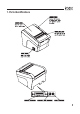
1.
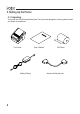
2. Setting Up the Printer 2-1. Unpacking Your printer box should include these items. If any items are damaged or missing, please contact your dealer for assistance.
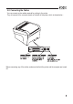
2-2. Connecting the Cables You can connect up the cables required for printing to the printer. They all connect to the connector panel on the back of the printer, which is shown below : Before connecting any of the cables, make sure that both the printer and the computer are turned off.
2-2-1.
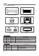
Centronics Parallel Interface PIN 1 2~9 10 11 12 13 14 15 16 17 18 19~30 31 32 33 34 35 36 SIGNAL STROBEDATA0~7 ACKBUSY PE SELECT AUTO FEEDGROUND GROUND NC LOGIC-H GROUND INITERRORGROUND NC +5V SELLECT IN- Ethernet Interface PIN 1 2 3 4 5 6 7 8 I/O Input Input/Output Output Output Output Output Input Input Output Input SIGNAL Data Out + Data Out GND Data IN + Data IN N.C N.C N.C DESCRIPTION Synchronize signal Data received Data bit Transmitted 0~7 Data receiving completed.
2-2-2. Cash Drawer Connector The printer can operate two cash drawers with a 6 pin RJ-11 modular connector. The driver is capable of supplying a maximum current of 1.0A/24VDC for 510ms or less when not printing. PIN 1 2 3 4 5 6 SIGNAL Signal GND Drawer kick-out drive signal 1 Drawer open/close signal +24V Drawer kick-out drive signal 2 Signal GND DESCRIPTION Output Input Output - Caution : To avoid an overcurrent, the resistance of the drawer kick-out solenoid must be 24 Ω or more.
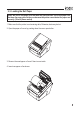
2-3. Loading the Roll Paper Notes: Be sure to use paper rolls that meet the specifications. Do not use paper rolls that have the paper glued to the core because the printer cannot detect the paper end correctly. (Turn off power switch) 1. Make sure that the printer is not receiving data; Otherwise, data may be lost. 2. Open the paper roll cover by pushing down the cover open button. 3. Remove the used paper roll core if there is one inside. 4. Insert new paper roll as shown.
5. Be sure to note the correct direction that the paper comes off the roll. 6. Pull out a small amount of paper, as shown. Then, close the cover. 7. Tear off the paper as shown.
2-4. Dip Switch Setting The printer is set up at the factory to be appropriate for almost all users. On the other hand, offers some more settings for users with special requirements. It has DIP switches that allow you to change communication setting, such as handshaking and parity check, as well as print density. Your printer has two sets of DIP switches. The functions of the switches are shown in the following tables. ♣Note : Power off. And open the cover of Dip Switch and change setting. 2-4-1.
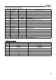
2-4-2. Parallel Interface Specification DIP Switch Set 1 Function SW 2 5 FUNCTION Hexadecimal Bi-Parallel mode ON HEXDUMP DISABLED Print Density (DIP-SW2) Print Density Low Power Normal Normal Dark OFF NORMAL ENABLED SW-1 ON OFF ON OFF DEFAULT OFF OFF SW-2 ON ON OFF OFF 2-4-3.
2-4-4.
2-4-5. Wi-fi Specification DIP Switch Set 1 Function SW 2 FUNCTION Hexadecimal Print Density (DIP-SW2) Print Density Low Power Normal Normal Dark ON HEXDUMP OFF NORMAL SW-1 ON OFF ON OFF DEFAULT OFF SW-2 ON ON OFF OFF 2-4-6.
DIP Switch Set 2 Functions Cutter SW 3 FUNCTION Cutter Emulation OFF PARTIAL CUT Remarks Only Epson mode SW-4 OFF SW-5 OFF FUNCTION Epson (TM-88) Paper low detect (*1) SW 6 ON FULL CUT FUNCTION Paper Low ON Detect OFF Do not Detect (*1) The detecting function of [Paper Low] is an option. Please set Dip Switch (2-6) [OFF] if you don't need any option. If Dip Switch is [ON] without any special option purpose. Printer detects [Paper is Low] and it could cause error.
♣CAUTION: Turn off the printer while removing the DIP switch cover to prevent an electric short, which can damage the printer. 1. Make sure the printer is turned off. 2. Remove the screw from the DIP switch cover. Then, take off the DIP switch cover as shown in the illustration below. 3. Set the switches using a pointed tool, such as tweezers or a small screwdriver. 4. Replace the DIP switch cover. Then, secure it with the screw. The new settings take effect when you turn on the printer.
♣CAUTION: When the paper is jammed with cutter, the top cover might be stuck. In this case, repeat power on and off several times. If the top cover is still stuck, please follow the steps to release the papers from jamming. 1. Make sure the printer is turned off. 2. Take out cutter cover as shown. 3. Turn screw with drivers to a direction until paper is released from the cutter.
3. Control panel and other functions. 3-1. Control panel You can control the basic paper feeding operations of the printer with the button on the control panel. The indicator lights help you to monitor the printer’s status. Control Panel Button The button can be disabled by the ESC c 5 command. Press the FEED button once to advance paper one line. You can also hold down the FEED button to feed paper continuously. 3-2.
4. Self Test The self-test lets you know if your printer is operating properly. It checks the control circuits, printer mechanisms, print quality, ROM version and DIP switch settings. This test is independent of any other equipment or software. Running the self test 1. Make sure the printer is turned off and the printer cover is closed properly. 2. While holding down the FEED button, turn on the printer using the switch on the front of the printer to begin the self-test.
5. Hexadecimal Dump This feature allows experienced users to see exactly what data is coming to the printer. This can be useful in finding software problems. When you turn on the hex dump function, the printer prints all commands and other data in hexadecimal format along with a guide section to help you find specific commands. To use the hex dump feature, follow these steps 1. After you make sure that the printer is off and Dip s/w 1-2 is ON, turn on the printer. 2.
6. Specifications Appendix A : Specifications 6-1. General Specifications (1) Printing Method Direct line thermal printing. (2) Print speed 200mm/sec. (Approx 35.4LPS) (3) Dot density 180 DPI (Hor / Ver) 180 / 180 (0.142mm / 0.142mm dot) (4) Printing Width 180 DPI Max 72mm (512 dots) (5) Number of print columns. No. of columns 180 DPI Font “A” Font “B” 42 56 (6) Roll paper Refer to chapter 2 for details on the recommended roll Paper. Paper width : 50mm~82.5mm Roll diameter : Max.
(8) Overall dimension 22
6-2. Auto Cutter Specifications (1) Cutting Frequency Max. 30 cuts per minute (2) Thickness of paper 0.065 ~ 0.1 mm (3) Cutter Life 1.0 million cuttings (if the paper thickness is between 65 and100µm) 6-3. Interface RS232C Serial Interface, Centronics Parallel Interface(IEEE1284), USB Interface USB COMBO Interface, Ethernet Interface(10Mbps), Wi-fi(802.11b) 6-4. Electrical Characteristics (1) Input Voltage DC 24V ± 10% (2) Current Consumption Operating: Approx. 1.
♣Important! When connecting or disconnecting the power supply from the printer, be sure that the following cautions are observed. (1) Use a power supply (Limited Power Supply) of DC 24V±10% and more than 2.5A. (2) Be careful about installing the printer in an area where there is noise. (3) Take the appropriate measure to protect against electrostatic AC line noise, etc. 6-5.
7. Command List No.
No. 41 42 43 44 45 46 47 48 49 50 51 52 53 54 55 56 57 58 59 60 61 62 1 2 3 4 5 6 7 8 9 10 26 Command ESC { FS p FS q GS ! GS $ GS * GS / GS B GS H GS I GS L GS P GS V GS W GS \ GS a GS f GS h GS k GS r GS v 0 GS w < Add > ESC i ESC m FS ! FS & FS FS .
27
POS-X, lnc. 2130 Grant Steet Bellingham, WA 98225 360-738-8433 support@pos-x.