
Printer User Manual
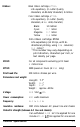

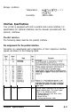
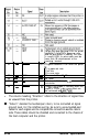

Table Of Contents
- FRONT MATTER
- TABLE OF CONTENTS
- INTRODUCTION
- CHAP 1-SETTING UP THE PRINTER
- CHAP 2-PAPER HANDLING
- CHAP 3-USING THE PRINTER
- CHAP 4-USING SOFTWARE AND GRAPHICS
- Using the LQ-2550 With Application Programs
- Computer-Printer Communication
- Enhancing Your Printing
- Graphics
- User-Defined Characters
- Designing Your Characters
- Design Grids
- Data Numbers
- Sending Information to Your Printer
- Printing User-Defined Characters
- Copying ROM Characters to RAM
- Letter Quality Characters
- Proportional Mode Characters
- Superscripts and Subscripts
- The Graphics Command
- Column Reservation Numbers
- A simple Graphics Program
- Using Hand-Calculated Data to Print Graphics
- Using Software and Graphics
- Mixing Print Styles
- CHAP 5-MAINTENANCE AND TRANSPORTATION
- CHAP 6-TROUBLESHOOTING
- Troubleshooting
- Problems and Solutions
- The Printer Does Not Print
- The Printer Stops Printing
- The Printout is Spaced Incorrectly
- The Printout is Faint or Uneven
- The Printout is Not what You Expect
- Single Sheets Do Not Feed Properly
- Continuous Paper Does Not Feed Properly
- Cut Sheet Feeder Does Not Load Paper Correctly
- The Short Tear-Off Feature Does Not Work Properly
- Color Printing Is Not What You Expect
- Data Dump Mode
- CHAP 7-USING PRINTER OPTIONS
- CHAP 8-COMMAND SUMMARY
- APPENDIX A-TECHNICAL SPECIFICATIONS
- GLOSSARY
- INDEX
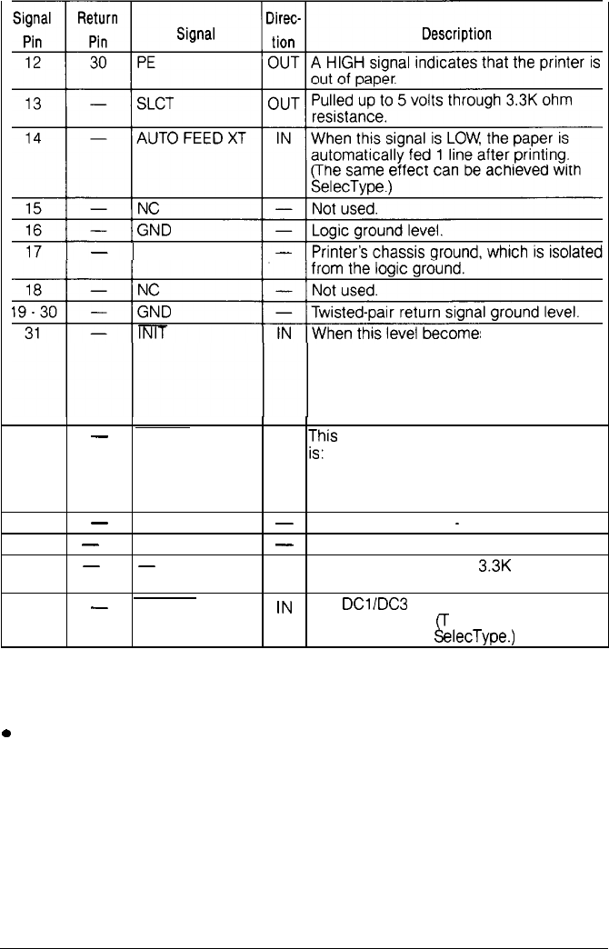
CHASSIS GND
32
-
ERROR
33
-
GND
34
-
NC
35
-
-
s
LOW, the printer
controller
is
reset to its power-up state
and the print buffer is cleared. This level
is usually HIGH; its pulse width must be
more than 50 microseconds at the
receiving terminal.
OUT
zis
level becomes LOW when the printer
1) in paper-out state
2) off line
3) in error state.
-
Same as for Pins 19
-
30.
-
Not used.
OUT Pulled up to 5V through
3.3K
ohm
resistance.
36
-
SLCT IN
lN
The
DClIDC3
code is valid only when this
signal is “HIGH”.
&Y
he same effect can
be achieved with
elecType.)
l
The column heading “Direction” refers to the direction of signal flow
as viewed from the printer.
0
“Return” denotes the twisted-pair return, to be connected at signal
ground level. For the interface wiring, be sure to use
a
twisted-pair
cable for each signal and to complete the connection
on
the return
side. These cables should be shielded and connected to the chassis of
the host computer and the printer.
A-10
Technical Specifications