Bedienungsanleitung Operating Manual MAX! Wandthermostat+ Funk-Wandthermostat MAX! Wireless Wall Thermostat+ (S. 2) (p.
Inhaltsverzeichnis 1. Einleitung und bestimmungsgemäßer Einsatz............3 2. Übersicht.......................................................................4 3. Bedienung und Display.................................................5 4. Sicherheitshinweise......................................................6 5. Entsorgungshinweise...................................................6 6. Batterien einlegen (wechseln)......................................7 7. Datum und Uhrzeit einstellen (dAt).............
1. Einleitung und bestimmungsgemäßer Einsatz Der MAX! Wandthermostat+ ist im MAX! System für die Regelung der Raumtemperatur zuständig. Mit dem MAX! Wandthermostat+ können bis zu 8 MAX! Heizkörperthermostate in einem Raum komfortabel reguliert werden. Der MAX! Wandthermostat+ verfügt über einen internen Sensor, der die Temperatur im Raum misst und zyklisch an die Heizkörperthermostate übermittelt. Die Kommunikation der MAX! Komponenten untereinander erfolgt bidirektional.
MAX! Raumlösung In der Raumlösung können Sie die Konfiguration aller angelernten Geräte in Ihrem Raum komfortabel über den MAX! Wandthermostat+ vornehmen. Bis zu 8 MAX! Heizkörperthermostat+ und 8 MAX! Fensterkontakte können über den MAX! Wandthermostat+ angelernt und gesteuert werden. Der MAX! Wandthermostat+ verfügt über einen internen Sensor, der die Temperatur im Raum misst und zyklisch an die Heizkörperthermostate übermittelt. Diese Lösung kann mit einem MAX! Cube zur Hauslösung erweitert werden. 2.
3.
4. Sicherheitshinweise Jeder andere Einsatz als der in dieser Bedienungsanleitung beschriebene ist nicht bestimmungsgemäß und führt zu Garantie- und Haftungsausschluss. Dies gilt auch für Umbauten und Veränderungen. Die Geräte sind ausschließlich für den privaten Gebrauch gedacht. Das Gerät ist kein Spielzeug, erlauben Sie Kindern nicht damit zu spielen. Lassen Sie Verpackungsmaterial nicht achtlos liegen, dies kann für Kinder zu einem gefährlichen Spielzeug werden.
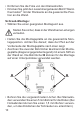
6. Batterien einlegen (wechseln) 1. Auslieferungszustand Wenn Sie das Gerät zum ersten Mal in Betrieb nehmen, entfernen Sie zunächst die Montageplatte auf der Rückseite des MAX! Wandthermostat+. • Halten Sie dazu den MAX! Wandthermostat+ in einer Hand fest und ziehen Sie die Montageplatte an einer Ecke ab. 2. Montierter Zustand Im montierten Zustand lässt sich der MAX! Wandthermostat+ einfach aus dem Rahmen und von der Montageplatte ziehen.
Das Batterie-leer-Symbol ( ) weist daraufhin, dass die Batterien auszutauschen sind. Wird zusätzlich ein „V“ oder ein „S“ angezeigt, müssen die Batterien eines angelernten Heizkörperthermostats (V) oder Fensterkontakts (S) ausgetauscht werden. Normale Batterien dürfen niemals aufgeladen werden. Es besteht Explosionsgefahr. Batterien nicht ins Feuer werfen! Batterien nicht kurzschließen! 7.
Wurde der MAX! Wandthermostat+ an den MAX! Cube angelernt, so erhält er anschließend von diesem das Datum und die Uhrzeit. Beim Betrieb ohne MAX! Cube können Datum und Uhrzeit jederzeit über „dAt“ im Konfigurationsmenü geändert werden. (siehe Kapitel 16). 8. Montage Sie können den MAX! Wandthermostat+ entweder im beiliegenden Rahmen an eine Wand schrauben/kleben oder in eine bestehende Schalterserie integrieren (Näheres zur Kompatibilität finden Sie in Kapitel 9).
• Entfernen Sie die Folie von den Klebestreifen. • Drücken Sie jetzt den zusammengebauten MAX! Wandthermostat+ mit der Rückseite an die gewünschte Position an die Wand. Schraub-Montage: • Wählen Sie einen geeigneten Montageort aus. Stellen Sie sicher, dass in der Wand keine Leitungen verlaufen. • Halten Sie die Montageplatte an die gewünschte Montageposition. Achten Sie darauf, dass der Pfeil auf der Vorderseite der Montageplatte nach oben zeigt.
• Montieren Sie die Montageplatte durch Eindrehen der mitgelieferten Schrauben und Dübel. • Setzen Sie nun den MAX! Wandthermostat+ im Rahmen auf die Montageplatte. Achten Sie darauf, dass die Pfeile auf der Rückseite des Wandthermostats nach oben zeigen und die Klammern der Montageplatte in die Öffnungen des Wandthermostats rasten. 9.
Hersteller Rahmen Berker S.1, B.1, B.3, B.7 Glas ELSO Joy GIRA System 55, Standard 55, E2, E22, Event, Espirit merten 1-M, Atelier-M, M-Smart, M-Arc, M-Star, M-Plan JUNG A 500, AS 500, A plus, A creation 10. Anlernen Um den MAX! Wandthermostat+ in Ihrer Installation nutzen zu können, muss er zunächst angelernt werden. Der Anlernvorgang unterscheidet sich nach der von Ihnen genutzten Systemvariante.
1. 2. > 3 Sek. • Das Antennensymbol erscheint im Display und der MAX! Wandthermostat+ erscheint in der MAX! Software. • Gehen Sie in der Software auf „Weiter“, um dem Gerät einen Namen zu geben und es einem Raum zuzuordnen. • Der MAX! Wandthermostat+ ist nun im System integriert und kann in der Software im jeweiligen Raum konfiguriert werden. Sobald der MAX! Wandthermostat+ an den MAX! Cube angelernt ist, erhält er Datum, Uhrzeit und Wochenprogramm vom MAX! Cube.
Wandthermostaten+ an. Diese übernehmen dann die Einstellungen des MAX! Wandthermostat+ (z.B. Modus, Temperatur, Wochenprogramm). Zum Anlernen gehen Sie wie folgt vor: • Versetzen Sie zunächst den Anlernpartner (z.B. den MAX! Heizkörperthermostat+) gemäß der entsprechenden Bedienungsanleitung in den Anlernmodus. • Aktivieren Sie den Anlernmodus am MAX! Wandther1. mostat+ mit einem langen Tastendruck der OK-Taste. > 3 Sek.
mostat+) abzulernen. Dabei werden alle Funkkomponenten gleichzeitig abgelernt. Gehen Sie zum Ablernen folgendermaßen vor: • Halten Sie die Mode-Taste für länger als 3 Sekunden gedrückt. • Wählen Sie mit den (+) und (-) Tasten den Menüpunkt UnL (Unlearn). • Bestätigen Sie Ihre Auswahl mit der OK-Taste. • Im Display erscheint ACC (Accept). Bestätigen Sie den Ablern-Vorgang mit der OK-Taste.
In der MAX! Hauslösung nehmen Sie die Einstellungen für den MAX! Wandthermostat+ über die MAX! Software vor. In der MAX! Raumlösung können Sie die Funktionen über einen kurzen Druck der Mode-Taste wechseln. Wird der Betriebsmodus oder die Temperatur an einem Gerät im Raum geändert, übernehmen alle angelernten Heizkörperthermostate diese Änderung. 13. Kindersicherung / Bediensperre ( ) Die Bedienung des MAX! Wandthermostat+ kann gesperrt werden, um das ungewollte Verändern von Einstellungen, z.B.
15. Frostschutzbetrieb einstellen (OFF) Wenn der Raum nicht geheizt werden soll, können die Ventile der Heizkörper geschlossen werden. Nur bei Frostgefahr werden sie geöffnet. Der Verkalkungsschutz wird dabei weiter durchgeführt. Zum Aktivieren gehen Sie wie folgt vor: • Betätigen Sie die (-) Taste im manuellen Betrieb (Manu) so lange, bis im Display „OFF“ erscheint. • Zum Beenden verlassen Sie den manuellen Betrieb (Manu) oder drücken Sie die (+) Taste. 16.
dAt: Ändern von Uhrzeit und Datum (Abschnitt 7.) UnL: Ablernen von Funkkomponenten (UnL) (Abschnitt 11.) Pro: Einstellen des Wochenprogramms (Ab schnitt 16.1) Anzeige von Uhrzeit und Datum umschalten (Abschnitt 16.2) t-d: Komfort- und Absenktemperatur einstellen (Abschnitt 16.4) S-A: Ändern der Displayanzeige von Soll- und IstTemperatur (Abschnitt 16.3) bOS: Einstellen der Ventilöffnung und der Dauer der Boost-Funktion (Abschnitt 16.5) Urlaubsfunktion einstellen (Abschnitt 16.
• Drücken Sie die Mode-Taste länger als 3 Sekunden. Im Display erscheint „Pro“. • Bestätigen Sie mit der OK-Taste. Im Display erscheint „dAy“. • Wählen Sie mit den (+) und (-) Tasten einen einzelnen Wochentag, alle Werktage, das Wochenende oder die gesamte Woche aus (Bsp. Werktage). • Bestätigen Sie Ihre Auswahl mit der OK-Taste. • Stellen Sie nun die Endzeit mit den (+) und (-) Tasten des ersten Zeitabschnitts ein (Bsp. 6:00 Uhr, für den Zeitraum von 0:00 – 6:00 Uhr).
Wochenprogramm: Beispiele Mit dem MAX! Wandthermostat+ können für jeden Wochentag bis zu 6 Heizzeiten (13 Schaltzeitpunkte) mit individueller Temperaturvorgabe hinterlegt werden. Werkseitig ist folgendes Wochenprogramm hinterlegt: Montag-Freitag: ab 00:00 bis 06:00 ab 06:00 bis 09:00 ab 09:00 bis 17:00 ab 17:00 bis 23:00 ab 23:00 bis 23:59 17.0°C 21.0°C 17.0°C 21.0°C 17.
Soll ein Raum (z.B. Badezimmer) auch zur Mittagszeit beheizt werden, kann eine Programmierung wie folgt aussehen: Montag bis Sonntag: ab 00:00 bis 06:00 15.0°C ab 06:00 bis 09:00 23.0°C ab 09:00 bis 12:00 17.0°C ab 12:00 bis 14:00 19.0°C ab 14:00 bis 18:00 17.0°C ab 18:00 bis 22:00 21.0°C ab 22:00 bis 23:59 15.
16.2 Anzeige Uhrzeit/Datum einstellen (t-d) Werkseitig wird im Display die Uhrzeit angezeigt. Über das Menü können Sie statt der Uhrzeit das Datum anzeigen lassen. • Öffnen Sie durch langen Tastendruck (länger als 3 Sek.) der Mode-Taste das Konfigurationsmenü. • Wählen Sie den Menüpunkt „t-d“ mit den (+) und (-) Tasten aus und bestätigen Sie mit der OK-Taste. • Stellen Sie mit den (+) und (-) Tasten das anzuzeigende Format im Display ein (Datum und Uhrzeit wechseln in der Anzeige).
16.4 Komfort- und Absenktemperatur einstellen Die Komfort ( )- und die Absenk-Taste ( ) dienen zum komfortablen und einfachen Umschalten zwischen Komfort- und Absenktemperatur. Werkseitig liegen diese bei 21.0°C und 17.0°C. Beim Einsatz ohne MAX! Cube passen Sie die Werte über die jeweilige Taste (Komfort- bzw. Absenktemperatur) wie folgt am Gerät an: • Halten Sie die Komfort( )-Taste lange gedrückt, um die Komfort-Temperatur anzupassen bzw. die Absenk-Taste ( ), um die Absenktemperatur anzupassen.
mit der vorher eingestellten Temperatur. • Die Boost-Funktion lässt sich jederzeit vorzeitig durch nochmaliges Betätigen der OK-Taste deaktivieren. Die verbleibende Funktionsdauer wird im Sekundentakt heruntergezählt (z.B. „300“ bis „000“) und BOOST wird im Display dargestellt. Die Dauer und Ventilöffnung der Boost-Funktion lassen sich individuell anpassen: • Drücken Sie die Mode-Taste länger als 3 Sekunden. • Wählen Sie mit den (+) und (-) Tasten den Menüpunkt „bOS“ aus.
Ist die Dauer der Boost-Funktion (z.B. über den MAX! Cube) so eingestellt, dass die Anzeige im Display eine Anzeige von 999 Sek. überschreitet, wird sie in Minuten dargestellt. 16.6 Die Urlaubsfunktion einstellen ( ) Die Urlaubsfunktion kann genutzt werden, wenn während eines Urlaubs oder einer Party für einen bestimmten Zeitraum eine feste Temperatur gehalten werden soll. • Drücken Sie die Mode-Taste so oft kurz, bis im Display das Koffersymbol ( ) erscheint.
• Drücken Sie die Mode-Taste länger als 3 Sekunden. • Wählen Sie mit den (+) und (-) Tasten den Menüpunkt „dEC“ aus. • Bestätigen Sie die Auswahl mit der OK-Taste. • Wählen Sie mit den (+) und (-) Tasten den Wochentag aus. • Bestätigen Sie die Auswahl mit der OK-Taste. • Wählen Sie mit den (+) und (-) Tasten die Uhrzeit aus. • Bestätigen Sie die Auswahl mit der OK-Taste. Während die Entkalkungsfahrt ausgeführt wird, erscheint im Display „CAL“. 16.
16.9 Offset-Temperatur einstellen (tOF) Die Temperatur wird am MAX! Wandthermostat+ gemessen, deshalb kann es woanders im Raum kälter oder wärmer sein. Um dies anzugleichen, kann ein TemperaturOffset von ±3.5°C eingestellt werden. Werden z.B. 18°C anstatt eingestellter 20°C gemessen, ist ein Offset von -2.0°C einzustellen. • Drücken Sie die Menu-Taste länger als 3 Sekunden. • Wählen Sie mit den (+) und (-) Tasten den Menüpunkt „tOF“ aus. • Bestätigen Sie die Auswahl mit der OK-Taste.
• Drücken Sie die Mode-Taste länger als 3 Sekunden. • Wählen Sie mit den (+) und (-) Tasten den Menüpunkt „rES“ aus. • Bestätigen Sie die Auswahl mit der OK-Taste. • Es erscheint „ACC“ im Display, bestätigen Sie den Werksreset mit der OK-Taste. Ist der MAX! Wandthermostat+ an einen MAX! Cube angelernt, ist das Konfigurationsmenü am Gerät gesperrt. Sie können trotzdem ein Reset wie nachfolgend beschrieben ausführen: • Entfernen Sie eine Batterie und warten Sie 60 Sekunden.
Hiermit erklärt die eQ-3 Entwicklung GmbH, dass sich dieses Gerät in Übereinstimmung mit den grundlegenden Anforderungen und den anderen relevanten Vorschriften der Richtlinie 1999/5/EG befindet. Die vollständige Konformitätserklärung finden Sie unter www.eQ-3.de. 19.
20. Technische Daten Kurzbezeichnung: Versorgungsspannung: Stromaufnahme: Batterielebensdauer: Schutzart: Umgebungstemperatur: Abmessungen (B x H x T): Gewicht: Funkfrequenz: Empfängerklasse: Typ. Funk-Freifeldreichweite: Duty Cycle: Display: 30 BC-TC-C-WM-4 2x 1,5 V LR03/Micro/AAA 30 mA max. 2 Jahre (typ.
Maximal anlernbare Geräte: MAX! Hauslösung: • max. 50 Geräte in max. 10 Räumen, • max. 4 MAX! Eco Taster • pro Raum max. 8 MAX! Heizkörperthermostat(+), 8 MAX! Fensterkontakte und 1 MAX! Wandthermostat+ MAX! Raumlösung: • max. 1 MAX! Wandthermostat+ • max. 8 MAX! Heizkörperthermstat(+) • max. 8 MAX! Fensterkontakte MAX! Heizkörperlösung: • max. 2 MAX! Heizkörperthermostat+ • max. 3 MAX! Fensterkontakte Technische Änderungen sind vorbehalten.
Table of contents 1. Introduction and intended use................................... 33 2. Overview.................................................................... 34 3. Operation and display................................................ 35 4. Safety instructions..................................................... 36 5. Instructions for disposal............................................ 36 6. Inserting (replacing) batteries....................................37 7. Setting date and time (dAt)......
1. Introduction and intended use The MAX! Wall Thermostat+ can conveniently regulate the temperature in a room. With the MAX! Wall Thermostat+ up to 8 MAX! radiator thermostats can be regulated in a room. The MAX! Wall Thermostat+ has an internal sensor that measures the temperature in the room and cyclically transmits it to the radiator thermostats. Communication between MAX! components is bi-directional. This ensures that the information sent reaches the recipient.
MAX! Room Solution In the room solution, the settings of all connected devices in your room can comfortably be made via the MAX! Wall Thermostat+. Up to 8 MAX! Radiator Thermostat+ and 8 MAX! Window Sensors can be connected and controlled via the MAX! Wall Thermostat+. The MAX! Wall Thermostat+ has an internal sensor that measures the temperature in the room and cyclically transmits it to the radiator thermostats. With a MAX! Cube, the solution can be extended to a House Solution. 2.
3.
4. Safety instructions Using this device for any purpose other than that described in this operating manual does not fall within the scope of intended use and shall invalidate any warranty or liability. This also applies to any conversion or modification work. This device is intended for private use only. This device is not a toy; do not allow children to play with it. Do not leave packaging material lying around, as it can be dangerous in the hands of a child.
6. Inserting (replacing) batteries 1. As-delivered condition When you are starting up the device for the first time, first remove the mounting plate (A) on the rear of the wall thermostat (C). • To do this, hold the MAX! wall thermostat firmly in one hand and pull off the installation plate at one corner. 2. Installed condition Once mounted, the MAX! wall thermostat can easily be pulled out of the frame. • Pull the wall thermostat (C) off the wall together with the frame by pulling sideways at the frame.
An empty battery symbol ( ) indicates that the batteries need to be replaced. If, in addition, a V or S are displayed, the batteries of a taught-in Heating Thermostat (V) or Window Sensor (S) have to be replaced. Never recharge standard batteries. Doing so will present a risk of explosion. Do not throw the batteries into a fire. Do not short-circuit batteries. 7. Setting date and time (dAt) After inserting or replacing batteries the firmware version number will be shown briefly.
If the MAX! wall thermostat was taught-in to the MAX! cube, the current date and time will be transferred to the MAX! wall thermostat automatically. During operation without the MAX! Cube date and time can be changed at any time via „dAt“ in the configuration menu (see section 17). 8. Mounting You can either use screws or adhesive strips to mount the MAX! wall thermostat to a wall in the frame supplied or integrate it into an existing switch (please refer to sec. 9).
• Remove the protective film from the adhesive strip. • Press the assembled MAX! Wall Thermostat+ with the back side to the wall in the position where it should subsequently be attached. Screw mounting: • Choose a site for installation. Make sure that electrical lines in the wall will not be damaged. • Position the mounting plate on the desired site on the wall. Make sure that the arrow on the mounting plate is pointing upwards.
• Use the screws and plugs supplied to fasten the mounting plate to the wall. • Attach the wall thermostat with the frame on the mounting plate. Make sure that the arrows on the back side of the wall thermostat point upwards and that the clips on the mounting plate latch into the openings on the wall thermostat. 9.
Manufacturer Frame Berker S.1, B.1, B.3, B.7 Glas ELSO Joy GIRA System 55, Standard 55, E2, E22, Event, Espirit merten 1-M, Atelier-M, M-Smart, M-Arc, M-Star, M-Plan JUNG A 500, AS 500, A plus, A creation 10. Teaching-in of MAX! components In order to use the MAX! Wall Thermostat+ in your installation, you must teach it in to the MAX! system. The teachin procedure depends on the system variant used. Choose your system variant and follow the instructions below.
• The antenna symbol appears in the display and the MAX! Wall Thermostat+ appears in the MAX! software. • In to software, go to „Next“ to give the device a name and assign it to a room. • The MAX! Wall Thermostat+ is now integrated into the system and can be configured for each room via the MAX! software. As soon as the MAX! Wall Thermostat+ has been taught in to the MAX! Cube, all data such as date, time or week programme are transmitted to it via radio connection.
1. > 3 Sek. • The antenna symbol ( ) and the remaining teach-in time (30 seconds) will be displayed. • If teach-in has been successful, the MAX! Wall Thermostat + will change back to normal operating mode. 11. Teaching-out of wireless components (UnL) In the MAX! House Solution, unlearning of the MAX! Wall Thermostat+ will be made via the MAX! software. In the MAX! Room Solution, use the function „UnL“ in the menu to unlearn devices that are taught-in to the MAX! Wall Thermostat+.
leted from the MAX! Wall Thermostat+; factory setting is not mandatory. 12. Operating modes (Auto / Manu / Holiday function / Boost) You can choose between the operating modes auto, manu and holiday function: Auto: Week programme – automatic temperature control according to stored week programme. Manu: Manual operation – the temperature is set manually with the (+) and (-) buttons. Holiday function ( ): Setting a temperature that should be held until a fixed end time.
13. Child-proof lock / operating lock ( ) Operation of the device can be locked to avoid unintended changes through involuntary touch. To (de)activate the operating lock proceed as follows: • Briefly press the Mode and the OK button simultaneously. • Once activated, the operating lock symbol ( ) is shown on the display. 14. Setting heat pause (ON) Battery life can be prolonged by switching the heating off in summer.
16. Configuration menu (Menu) If you use the MAX! Wall Thermostat+ in a MAX! House Solution, you can conveniently set the functions described in the following chapters in the MAX! Software in each room. The following steps explain how these functions are set in the MAX! Room Solution. In connection with the MAX! Cube, these functions are deactivated at the MAX! Wall Thermostat+. When using the device within the MAX! Room Solutions, the settings can be made in the configuration menu.
Set holiday function (sec. 16.6) dEC: Set valve protection function (sec. 16.7) AEr: Set “Open window temperature” for automatic temperature decrease during airing (sec. 16.8) tOF: Set temperature offset (sec. 16.9) rES: Reset factory settings (sec. 17.) 16.1 Setting the week programmes(Pro) In the week programme, for each weekday up to 6 heating phases (13 change settings) can be set separately.
• Confirm setting with the OK button. • Repeat this procedure until temperatures are stored for the entire period between 0:00 and 23:59. In Auto mode the selected week programme will be automatically adopted by all taught-in MAX! Radiator Thermostats. In Auto mode the temperature can be changed at any time with the (+) and (-) buttons or comfort ( ) and reduced temperature ( ) buttons. The adjusted temperature will be maintained until the next phase in the timer programme starts.
In the display, bars for heating phases are displayed whenever the set temperature for the period is higher than the set reduction temperature. If you want a room (e.g. the bathroom) to also be heated during lunchtime the programming could look as follows: Monday - Sunday: from 00:00 to 06:00 15.0°C from 06:00 to 09:00 23.0°C from 09:00 to 12:00 17.0°C from 12:00 to 14:00 19.0°C from 14:00 to 18:00 17.0°C from 18:00 to 22:00 21.0°C from 22:00 to 23:59 15.0°C 16.
(date and time will switch on the display) with the (+) and (-) buttons. • Confirm setting with the OK button. 16.3 Switching nominal/actual temperature (S-A) In the factory settings, the display will show the nominal temperature. In the configuration menu, you can change the display setting from nominal to actual temperature. • Open the configuration menu by pressing the menu button. • Select the (S-A) menu item with the (+) and (-) buttons and confirm with the OK button.
• Press the comfort ( ) / reduced ( ) temperature button for a few seconds. • The display shows the respective symbol and the corresponding comfort or reduced temperature. • Change the temperature with the (+) and (-) buttons. • Confirm setting with the OK button. Even in Auto mode the temperature can be changed with this button at any time. However, the change will only be maintained until the next phase the timer programme starts. 16.
• • • • Press the Menu button for more than 3 seconds. Select the “bOS” menu item with the (+) and (-) buttons. Confirm the setting with the OK button. Use the (+) and (-) buttons to set the duration of the Boost from 0 to 30 minutes (0, 5, 10, 15, 20, 25, 30 mins.). Choosing 0 will deactivate this function. • Confirm the setting with the OK button. • Subsequently set the valve opening between 0 and 100% in 5% increments with the (+) and (-) buttons.
to be held. • Confirm the setting with the OK button. • Set the end date until which you want the holiday function to be set. • Confirm the setting with the OK button. • Set the temperature and press OK. The display will flash to confirm. The set temperature will remain until the set end time. Afterwards the MAX! wall thermostat will switch to Auto mode. Radio control commands like those from a window contact or the weekly de-scaling run will still be performed. 16.
16.8 Open window function / airing ( , AEr) During the airing of a room the MAX! Wall Thermostat+ will automatically reduce the room temperature to save heating costs. Meanwhile, in this phase the display of the MAX! Wall Thermostat+ and all taught-in devices will show the open window symbol ( ). Combined with a MAX! Window Sensor the opening and closing of a window will be detected time-accurate. The temperature will only be reduced to the factory setting of 12° C while the window is opened.
17. Teach-out / Reset (rES) The initial state of the MAX! Wall Thermostat+ can be restored manually, e.g. to teach-in a single MAX! Room Solution to a MAX! Cube or to re-install an incorrectly operating system. Restoring the initial state deletes all settings and information about taught-in devices. In the MAX! House Solution, first delete the device from the MAX! software before restoring the factory settings.
18. Information about radio operation Radio transmission is performed on a non-exclusive transmission path, which means that there is a possibility of interference occurring. Interference can also be caused by switching operations, electrical motors or defective electrical devices. The range of transmission within buildings can differ greatly from that available in the open air.
19. Remedy Error code on the display Problem Solution Battery symbol ( ) Battery voltage too low Replace batteries F4 MAX! Cube already taught-in Make sure the device is no longer taught-in to the Cube (in the software) and perform a reset. Then you can teach-in the device again.
20. Technical data Short description: Supply voltage: Current consumption: Battery life: Protection: Ambient temperature: Dimensions (W x H x D): Weight: Receiver frequency: Receiver category: Typ. open area RF range: Duty Cycle: Display: BC-TC-C-WM-4 2x 1,5 V LR03/Micro/AAA 30 mA max. 2 years (typ.) IP20 5 to 55 °C 86 x 86 x 21,5 mm 79 g (without batteries) 868,3 MHz SRD Class 2 > 100 m < 1% per h LC-Display Maximum number of devices to teach-in: MAX! House Solution: • max. 50 devices in max.
eQ-3 AG Maiburger Straße 29 D-26789 Leer www.eQ-3.