
User guide


User Guide V1.10
9
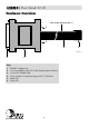
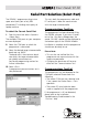
Hardware Installation Instructions continued
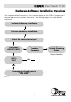
Installation Instructions
See Figure 6
1 Ensure power to both PC and target systems is switched off.
2 Connect the serial cable provided to a spare COM port on the PC using the 9-25 way
adaptor if necessary.
3 Connect the GEMINI-1 to the other end of the serial cable.
4 Connect the IDC plug at the end of the ISP cable into the 10-way IDC header on the user
target board (not supplied).
NOTE: The PC serial cable used must be of the same specification as the one supplied
with the system. Failure to use the correct serial cable may result in the programmer not
working.
5 Apply power to the target board. Please ensure that the target system is powered up.
The programmer will not operate unless a Vcc in the specified range is applied on pin 1 of
the IDC connector. (The GEMINI-1 draws its power from the target)
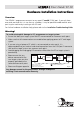
Warning!
The Gemini programmer features an on-board Vpp generator circuit which produces a Vpp
of +12V on the Vpp pin of the programmer under control of the Gemini driver software.
Please take the following points into consideration when using the programmer:
1 The programmer will always output Vcc on the Vpp line, except during programming of
a Philips P89C51Rx+ device.
2 If the selected devices requires a Vpp of +12V to be applied, the programmer will switch
the Vpp line from Vcc to +12V to commence the programming operation. This voltage
will only be released at the end of the programming operation.
3 When the programmer switches on the Vpp generator, a large surge current is drawn
from the target system supply. This can be as high as 700mA for a period of a few
milliseconds. If your target system can not supply this inrush current, you may find the
target system power supply current limits and the programming operation will fail. In
these circumstances, it is necessary to use an external power supply which can cope with
the inrush current. This problem will only occur with the Philips P89C51Rx+ family which
require the +12V Vpp.