
Instruction manual


Instruction Manual
2
Installation
This section details how to install the optional Windows-based software, as well as how
to make the necessary physical connections between your peripherals and the KVM
switch. For best results, ensure that all of the computers to be controlled are located as
close as possible to the KVM switch and console peripherals (monitor, keyboard, mouse),
as this will reduce the length of cabling required and reduces the chance of interference.
Installing the KVM Client application
Please note: The KVM Software supports only the Windows operating system. When
using other operating systems such as Linux, you can still use the keyboard hotkey
ScrLK + ScrLK to switch PCs, however this hotkey is not available on non-PC platforms
such as Mac OS, however an IBM keyboard can be used at the console to control Apple
Mac computers. Please note: Hotkey support is not natively supported in Mac OS. If
you are using a Mac OS, you must use the KVM buttons to switch between computers.
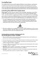
1. For each computer that will be connected to the KVM switch, please insert the
companion CD ROM into your CD drive. The installation program USBKVMIn.exe
should run automatically, however if it does not, please locate the le on the disk
and double-click on the icon to launch the application:
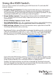
2. After the installation has completed, you will see a KVM Switcher icon on the system
tray of your Windows desktop. Right-click on the icon to launch the operation menu,
and double-click to evoke the conguration box.
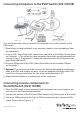
Connecting console components to
the KVM Switch (SV211KUSB)
1. Place the KVM switch in close proximity to the keyboard, mouse and monitor you
wish to use as the shared console controls.
2. Connect the monitor to the VGA port (Blue) located on the front panel of the switch.
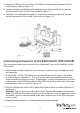
3. Connect a USB keyboard to the USB Type A connector on the front panel of the
switch, as shown in Figure 1-2 (page 3).
4. Connect a USB mouse to the USB Type A connector on the front panel of the switch,
as shown in Figure 1-2 (page 3).
5. Optional: Connect speakers to the green 3.5mm phono connector located on the
front panel of the switch, as shown in Figure 1-2 (page 3).
6. Optional: Connect a microphone to the pink 3.5mm phono connector located on
the front panel of the switch, as shown in Figure 1-2 (page 3).