
Instruction manual


Instruction Manual
4
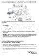
4. Connect a USB mouse to the Type A USB Port located on the front panel of the
switch. Please refer to Figure 1-3.
5. Connect speakers to the green 3.5mm phono connector (optional), located on
the front panel of the switch. Please refer to Figure 1-3.
6. Connect a microphone to the pink 3.5mm phono connector (optional) located
on the front panel of the switch. Please refer to Figure 1-3.
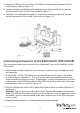
Connecting Computers to the KVM Switch (SV411KUSB)
This section describes how to connect the computer(s) you wish to control, to the
KVM switch.
1. Remove any existing keyboards, mice, monitors, speakers, and microphones from
the computer.
2. Using an HD-15 VGA+USB Cable, connect the VGA portion (15-pin) to the Video
Out connector on computer 1. (This will be the same connector from which you
disconnected the monitor in step 1, if applicable.) Connect the opposite end of the
cable to one of the VGA/Data ports on the KVM Switch, (located on the side or rear
panel of the switch) as shown in Figure 1-3.
3. Plug the USB portion of the USB + Video Data Cable into an available USB port on
computer 1.
Optional: If you wish to use audio, connect the Speaker/Microphone combination
cable to the Mic and Speaker out ports on the computer. Insert the opposite ends of
the cable(s) into the corresponding audio ports located next to the VGA/Data port
used in step 2.
4. Repeat the above process to connect the remaining computers.
Figure 1-3