
User`s manual

DemoKit-LG2 User’s Manual
18
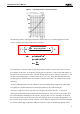
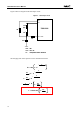
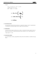
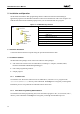
Figure 9 shows a diagram of the dual-slope circuit:
Figure 9. Dual-Slope Circuit
R6
R5
R7
C18
S1
(R
T
)
P02
P03
P00 / TI000
78K0/LG2
R
REF
= R6
R
VAR
= R5 + R
T
R
T
= temperature sensor resistance
R6
R5
R7
C18
S1
(R
T
)
P02
P03
P00 / TI000
78K0/LG2
R
REF
= R6
R
VAR
= R5 + R
T
R
T
= temperature sensor resistance
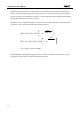
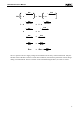
The charging time of the capacitor can be calculated as follows:
V
C
= V
DD
1 - e
t
R x C
-
= 1 - e
t
R x C
-
V
DD
V
C
= e
R x C
-
V
DD
V
C
t
1 -
R x C
t
V
DD
V
C
1 -
= ln
V
DD
V
C
1 -t = - R x C x ln
-
V
C
= V
DD
1 - e
t
R x C
-
= 1 - e
t
R x C
-
V
DD
V
C
= e
R x C
-
V
DD
V
C
t
1 -
R x C
t
V
DD
V
C
1 -
= ln
V
DD
V
C
1 -t = - R x C x ln
-